

Craftsman 351226060 Owner’s Manual

Operator's Manual
CRRFT$IRNo
6 x 48" Belt
12" Disc
SANDER
Model No.
351.226060
CAUTION: Read and follow
all Safety Rules and Operating
Instructions before First Use
of this Product.
Sears, Roebuck and Co., Hoffman Estates, IL 60179 U.S.A.
2643.01 Draft (01/12/01)
Warranty ....................................... 2
Safety Rules .................................... 2
Unpacking ..................................... 3
Assembly ..................................... 3-4
Installation .................................... 4-5
Operation .................................... 5-8
Maintenance .................................... 8
Troubleshooting ................................. 9
Parts iflustration and List ....................... 16-13
Espafiol .................................... 14-23
FULL ONE YEAR WARRANTY ON CRAFTSMAN
BELT & DISC SANDER
If within one full year from the date of purchase, this
Craftsman sander fails due to a defect in material or work-
manship, Sears will repair it free of charge. Warranty service
is available by contacting Sears in-home major brand repair
service.This warranty gives you specific legal rights and you
may also have other rights which vary from state to state.
If this sander is used for commercial purposes, this warranty
applies for only 90 days from the date of purchase.
Sears, Roebuck and Co., Dept. 817WA, Hoffman Estates, IL
60179
WARNING: For your own safety, read all of the instructions
and precautions before operating tool.
CAUTION: Always follow proper operating procedures as
defined inthis manual even ifyou are familiar with use of this
or similar tools. Remember that being careless for even a
fraction of a second can result insevere personal injury.
BE PREPARED FOR JOB
• Wear proper apparel. Do not wear loose clothing, gloves,
neckties, rings, bracelets or other jewelry which may get
caught in moving parts of machine.
• Wear protective hair covering to contain long hair.
• Wear safety shoes with non-slip soles.
• Wear safety glasses complying with United States ANSI
Z87.1. Everyday glasses have only impact resistant lenses.
They are NOT safety glasses.
• Wear face mask or dust mask if operation is dusty.
• Be alert and think clearly. Never operate power tools when
tired, intoxicated or when taking medications that cause
drowsiness.
PREPARE WORK AREA FOR JOB
• Keep work area clean. Cluttered work areas inviteaccidents.
• Do not use power tools in dangerous environments. Do not
use power tools in damp or wet locations. Do not expose
power tools to rain.
• Work area should be properly lighted.
• Proper electrical receptacle should be available for toot.
Three prong plug should be plugged directly into properly
grounded, three-prong receptacle.
• Extension cordsshould have a grounding prong and the three
wires ofthe extension cord should be of the correct gauge.
• Keep visitors at a safe distance from work area.
• Keep children out of workplace. Make workshop childproof.
Use padlocks, master switches or remove switch keys to
prevent any unintentional use of power tools.
TOOL SHOULD BE MAINTAINED
• Always unplug tool prior to inspection.
• Consult manual for specific maintaining and adjusting
procedures.
• Keep tool lubricated and clean for safest operation.
• Remove adjusting tools. Form habit of checking to see that
adjusting tools are removed before switching machine on.
• Keep all parts in working order. Check to determine that the
guard or other parts will operate properly and perform their
intended function.
• Check for damaged parts. Check for alignment of moving
parts, binding, breakage, mounting and any other condition
that may affect a tool's operation.
• A guard or ether part that is damaged should be properly
repaired or replaced. Do not perform makeshift repairs,
(Use parts list provided to order replacement parts.)
KNOW HOW TO USE TOOL
• Use right tool forjob. Do not force tool or attachment to do
a job for which it was not designed.
• Disconnect tool when changing belt or abrasive disc.
• Avoid accidental start-up. Make sure that the tool is in the
"OFF' position before plugging in.
• Do not force tool. It will work most efficiently at the rate for
which it was designed.
• Keep hands away from moving parts and sanding surfaces.
• Never leave tool running unattended. Turn the power off
and do not leave tool until itcomes to a complete stop.
• Do not overreach. Keep proper footing and balance.
• Never stand on tool. Serious injury could occur if tool is
tipped or if belt or disc are unintentionally contacted.
• Know your tool. Learn the tool's operation, application and
specific limitations.
• Use recommended accessories (refer to page 11). Use of
improper accessories may cause risk of injuryto persons.
• Handle the workpiece correctly. Protect hands from possi-
ble injury.
• Turn machine off if it jams. Belt jams when it digs too
deeply into workpiece. (Motor force keeps it stuck in the
work.)
• Support workplace with miter gauge, belt platen or work
table.
• Maintain '/,," maximum clearance between table and sand-
ing belt or disc.
CAUTION: Think safety! Safety is a combination of operator
common sense and alertness at all times when tool is being
used.
WARNING: Do not attempt to operate tool until it is com-
pletely assembled according to the instructions.
2
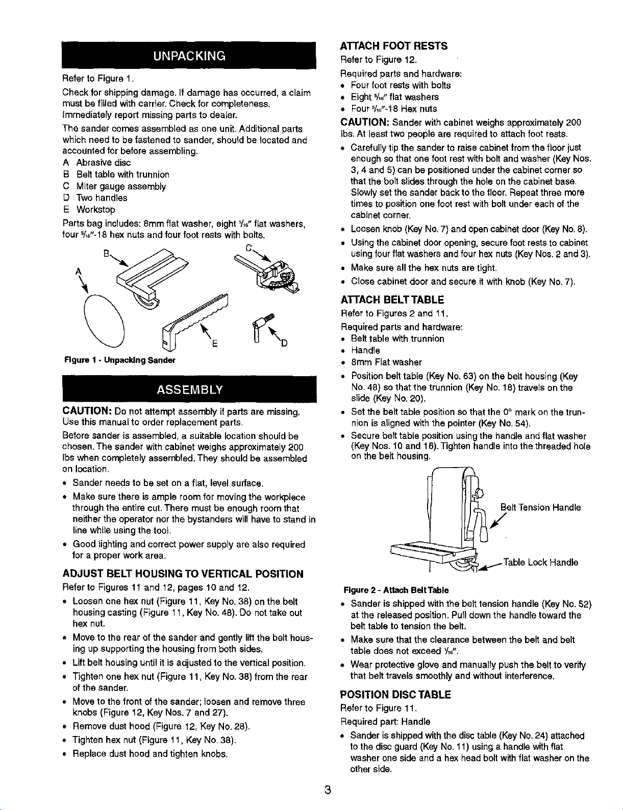
Refer to Figure 1.
Check for shipping damage. If damage has occurred, a claim
must be filled with carrier. Check for completeness.
Immediately report missing parts to dealer.
The sander comes assembled as one unit. Additional parts
which need to be fastened to sander, should be located and
accounted for before assembling.
A Abrasive disc
B Belt table with trunnion
C Miter gauge assembly
D Two handles
E Workstop
Parts bag includes: 8mm flat washer, eight %_"fiat washers,
four '/_"-18 hex nuts and four foot rests with bolts.
A
Figure I - Unpacking Sander
CAUTION: Do not attempt assembly if parts are missing,
Use this manual to order replacement parts.
Before sander is assembled, a suitable location should be
chosen. The sander with cabinet weighs approximately 200
Ibs when completely assembled. They should be assembled
on location.
• Sander needs to be set on a flat, level surface.
• Make sure there is ample room for moving the workpiece
through the entire cut. There must be enough room that
neither the operator nor the bystanders will have to stand in
line while using the tool,
• Good lighting and correct power supply are also required
for a proper work area.
ADJUST BELT HOUSING TO VERTICAL POSITION
Refer to Figures 11 and 12, pages 10 and 12.
• Loosen one hex nut (Figure 11, Key No. 38) on the belt
housing casting (Figure 11, Key No, 48). Do not take out
hex nut.
• Move to the rear of the sander and gently lift the belt hous-
ing up supporting the housing from both sides,
• Lift belt housing until it is adjusted to the vertical position.
• Tighten one hex nut (Figure 11, Key No. 38) from the rear
of the sander,
• Move to the front of the sander; loosen and remove three
knobs (Figure 12, Key Noa. 7 and 27).
• Remove dust hood (Figure 12, Key No. 28).
• Tighten hex nut (Figure 11. Key No. 38).
• Replace dust hood and tighten knobs.
ATTACH FOOT RESTS
Refer to Figure 12.
Required parts and hardware:
• Four foot rests with bolts
• Eight 5/_,,flat washers
• Four5/_,'-18 Hex nuts
CAUTION: Sander with cabinet weighs approximately 200
Ibs. At least two people are requLred to attach foot rests.
• Carefully tip the sander to raise cabinet from the floor just
enough so that one foot rest with bolt and washer (Key Nos.
3, 4 and 5) can be positioned under the cabinet corner so
that the bolt slides through the hole on the cabinet base.
Slowly set the sander back to the floor. Repeat three more
times to position one foot rest with bolt under each of the
cabinet corner.
• Loosen knob (Key No. 7) and open cabinet door (Key No. 8).
• Using the cabinet door opening, secure foot rests to cabinet
using four flat washers and four hex nuts (Key Nos. 2 and 3).
• Make sure all the hex nuts are tight.
• Close cabinet door and secure it with knob (Key No. 7),
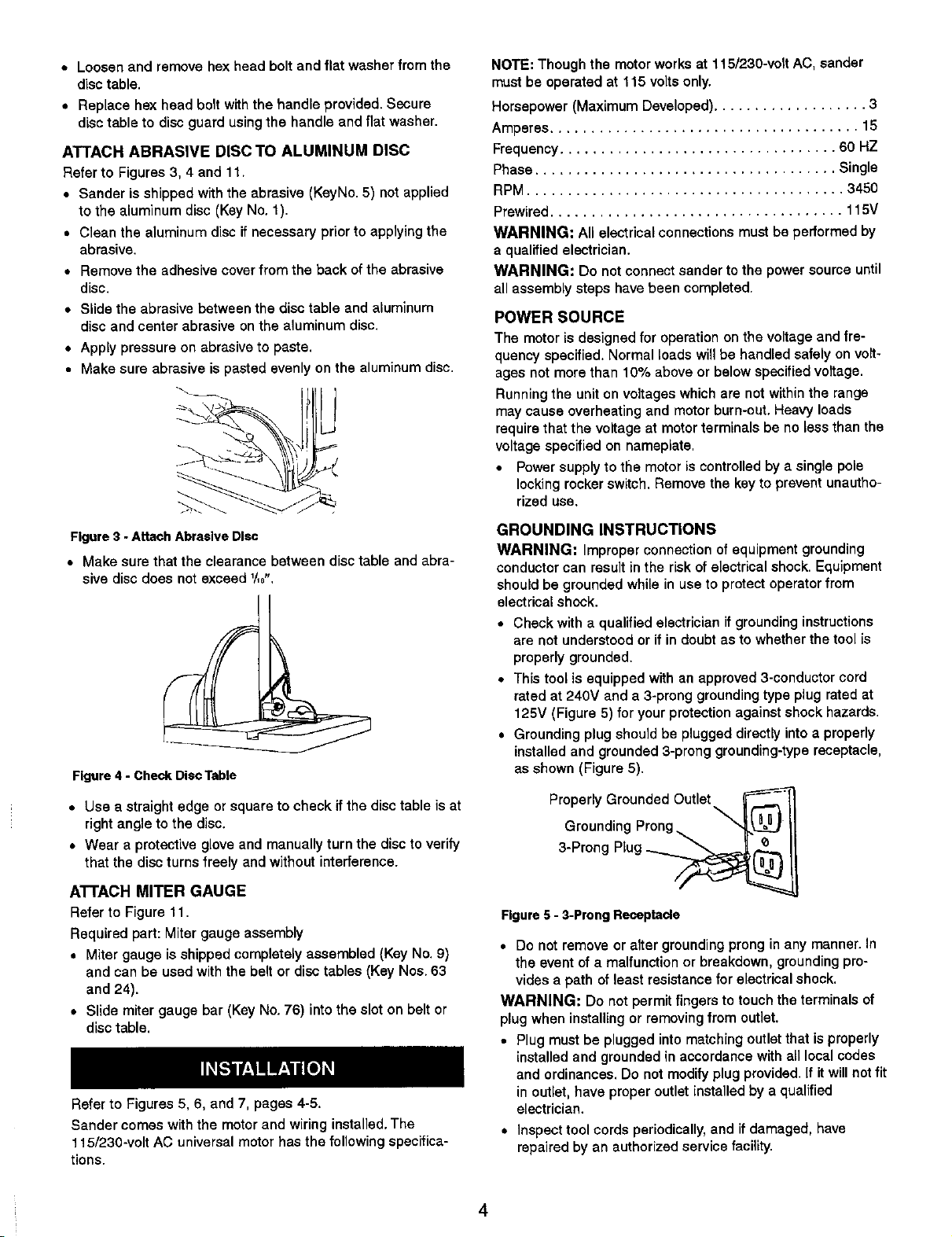
ATTACH BELT TABLE
Refer to Figures 2 and 11.
Required parts and hardware:
• Belt table with trunnion
• Handle
• 8mm Flat washer
• Position belt table (Key No. 63) on the belt housing (Key
No. 48) so that the trunnion (Key No. 18) travels on the
slide (Key No. 20).
• Set the belt table position so that the 0° mark on the trun-
nion is aligned with the pointer (Key No. 54).
• Secure belt table position using the handle and flat washer
(Key Nos. 10 and 16), Tighten handle into the threaded hole
on the belt housing,
Belt Tension Handle
/
,_L.1..TableLock Handle
Figure2 - Attach BeltTable
• Sander is shipped with the belt tension handle (Key No. 52)
at the released position, Pull down the handle toward the
belt table to tension the belt.
• Make sure that the clearance between the belt and belt
table does not exceed '/16".
• Wear protective glove and manually push the belt to verify
that belt travels smoothly and without interference.
POSITION DISC TABLE
Refer to Figure 11.
Required part: Handle
• Sander is shipped with the disctable (Key No. 24) attached
to the disc guard (Key No. 11) using a handle with flat
washer one side and a hex head bolt with flat washer on the
other side,
3
• Loosen and remove hex head bolt and flat washer from the
disc table.
• Replace hex head bolt with the handle provided. Secure
disc table to disc guard using the handle and fiat washer.
ATTACH ABRASIVE DISC TO ALUMINUM DISC
Refer to Figures 3, 4 and 1t+
• Sander is shipped with the abrasive (KeyNo. 5) not applied
to the aluminum disc (Key No. 1).
• Clean the aluminum disc if necessary prior to applying the
abrasive.
• Remove the adhesive cover from the back of the abrasive
disc.
• Slide the abrasive between the disc table and aluminum
disc and center abrasive on the aluminum disc.
• Apply pressure on abrasive to paste.
• Make sure abrasive is pasted evenly on the aluminum disc.
NOTE: Though the motor works at 115/230-volt AC, sander
must be operated at 115 volts only.
Horsepower (Maximum Developed) ................... 3
Amperes ...................................... 15
Frequency .................................. 60 HZ
Phase ..................................... Single
RPM ....................................... 3450
Prewired .................................... 115V
WARNING: All electrical connections must be performed by
a qualified electrician.
WARNING: Do not connect sander to the power source until
all assembly steps have been completed.
POWER SOURCE
The motor is designed for operation on the voltage and fre-
quency specified. Normal loads will be handled safely on volt-
ages not more than 10% above or below specified voltage.
Running the unit on voltages which are not within the range
may cause overheating and motor burn-out. Heavy loads
require that the voltage at motor terminals be no less than the
voltage specified on nameplate.
• Power supply to the motor is controlled by a single pole
locking rocker switch. Remove the key to prevent unautho-
rized use.
Figure3 - Attach Abrasive Disc
• Make sure that the clearance between disc table and abra-
sive disc does not exceed 1/_,,
Figure 4 - Check Disc Table
• Use a straight edge or square to check if the disc table is at
right angle to the disc.
• Wear a protective glove and manually turn the disc to verify
that the disc turns freely and without interference.
ATTACH MITER GAUGE
Refer to Figure 11,
Required part: Miter gauge assembly
• Miter gauge is shipped completely assembled (Key No. 9)
and can be used with the belt or disc tables (Key Nos. 63
and 24).
• Slide miter gauge bar (Key No. 76) into the slot on belt or
disc table.
R_er to Figures 5, 6, and 7, pages 4-5.
Sander comes with the motor and wiring installed. The
115/230-volt AC universal motor has the following specifica-
tions.
GROUNDING INSTRUCTIONS
WARNING: Improper connection of equipment grounding
conductor can result in the rLskof electrical shock, Equipment
should be grounded while in use to protect operator from
elect rioal shock,
• Check with a qualified electrician if grounding instructions
are not understood or if in doubt as to whether the tool is
properly grounded.
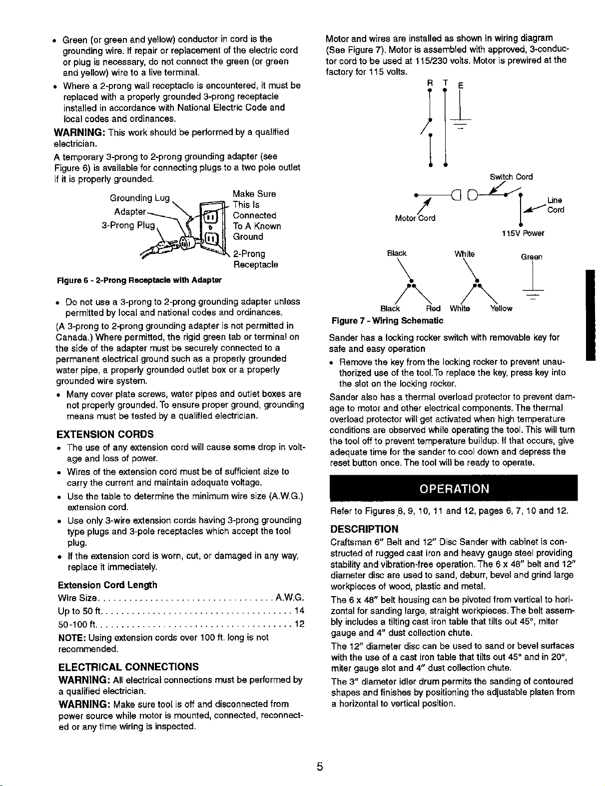
• This tool is equipped with an approved 3-conductor cord
rated at 240V and a 3-prong grounding type plug rated at
125V (Figure 5) for your protection against shock hazards.
• Grounding plug should be plugged directly into a properly
installed and grounded 3-prong grounding-type receptacle,
as shown (Figure 5).
ProP::LlyndGii ;u_ rdoendgOutIet _._
3 Prong Plug
Figure 5 - 3-Prong Receptacle
• Do not remove or alter grounding prong inany manner. In
the event of a malfunction or breakdown, grounding pro-
vides a path of least resistance for electrical shock.
WARNING: Do not permit fingers to touch the terminals of
plug when installing or removing from outlet.
• Plug must be plugged into matching outlet that is properly
installed and grounded in accordance with all local codes
and ordinances. Do not modify plug provided. If it will not fit
in outlet, have proper outlet installed by a qualified
electrician.
• Inspect tool cords periodically, and if damaged, have
repaired by an authorized service facility.
4
• Green (or green and yellow) conductor in cord is the
grounding wire. If repair or replacement of the electric cord
or plug is necessary, do not connect the green (or green
and yellow) wire to a live terminal.
• Where a 2-prong wall receptacle is encountered, it must be
replaced with a properly grounded 3-prong receptacle
installed in accordance with National Electric Code and
local codes and ordinances.
WARNING: This work should be performed by a qualified
electrician.
A temporary 3-prong to 2-prong grounding adapter (see
Figure 6) is available for connecting plugs to a two pole outlet
if it is properly grounded.
Groundin
3-Prong Plug
Make Sure
• This Is
Connected
To A Known
Ground
Motor and wires are installed as shown inwiring diagram
(See Figure 7). Motor is assembled with approved, 3-conduc-
tor cord to be used at 115/230 volts. Motor is prewired at the
factory for 115 volts.
R E
Switch Cord
Une
,_Cord
115VPower
2-Prong
Receptacle
Figure 6 - 2-Prong Receptacle with Adapter
* Do not use a 3-prong to 2-prong grounding adapter unless
permitted by local and national codes and ordinances.
(A 3-prong to 2-prong grounding adapter is not permitted in
Canada.) Where permitted, the rigid green tab or terminal on
the side of the adapter must be securely connected to a
permanent electrical ground such as a properly grounded
water pipe, a properly grounded outlet box or a properly
grounded wire system.
• Many cover plate screws, water pipes and outlet boxes are
not properly grounded. To ensure proper ground, grounding
means must be tested by a qualified electrician.
EXTENSION CORDS
• The use of any extension cord will cause some drop in volt-
age and loss of power.
• Wires of the extension cord must be of sufficient size to
carry the current and maintain adequate voltage.
• Use the table to determine the minimum wire size (A.W.G.)
extension cord.
• Use only 3-wire extension cords having 3-prong grounding
type plugs and 3-pole receptacles which accept the tool
plug.
• If the extension cord is worn, cut, or damaged in any way,
replace it immediately.
Extension Cord Length
Wire Size .................................. A.W.G.
Upto 50 ft..................................... 14
50-100 f_...................................... 12
NOTE: Using extension cords over 100 ft. long is not
recommended.
ELECTRICAL CONNECTIONS
WARNING: All electrical connections must be performed by
a qualified electrician.
WARNING: Make sure tool is off and disconnected from
power source while motor is mounted, connected, reconnect-
ed or any time wiring is inspected.
Black White Green
Black Red White Yellow
Figure 7 - Wiring Schematic
Sander has a locking rocker switch with removable key for
safe and easy operation
• Remove the key from the locking rocker to prevent unau-
thorized use of the tool.To replace the key, press key into
the slot on the locking rocker.
Sander also has a thermal overload protector to prevent dam-
age to motor and other electrical components. The thermal
overload protector will get activated when high temperature
conditions are observed while operating the tool. This will turn
the tool off to prevent temperature buildup, if that occurs, give
adequate time for the sander to cool down and depress the
reset button once. The tool will be ready to operate.
Refer to Figures 8, 9, 10, 11 and 12, pages 6, 7, 10 and 12.
DESCRIPTION
Craftsman 6" Belt and 12" Disc Sander with cabinet is con-
structed of rugged cast ironand heavy gauge steel providing
stability and vibration-free operation. The 6 x 48" belt and 12"
diameter disc are used to sand, deburr, bevel and grind large
workpieces of wood, plastic and metal.
The 6 x 48" belt housing can be pivoted from vertical to hori-
zontal for sanding large, straight workpieces. The belt assem-
bly includes a tilting cast irontable that tilts out 45°, miter
gauge and 4" dust collection chute.
The 12" diameter disc can be used to sand or bevel surfaces
with the use of a cast iron table that tilts out 45° and in 20 °,
miter gauge slot and 4" dust collection chute.
The 3" diameter idler drum permits the sanding of contoured
shapes and finishes by positioning the adjustable platen from
a horizontal to vertical position.
I
The two dust collection chutes accept the standard 4" dust
collection hose for quick removal of dust. The adjustable miter
gauge can be used on both the belt and disc tables for guid-
ing the workpiece at a desired angle while sanding.
SPECIFICATIONS
Belt size ............................ 6 x 48", 100 grit
Belt platen area .......................... 6% x 167/8"
Belt table dimensions ....................... 5'/8x 9'/8"
Belt table tilts .............................. 0 to 45°
Belt dust chute diameter .......................... 4"
Belt speed .............................. 1570 FPM
Disc diameter .......................... 12", 100 grit
Disc table dimensions ........................ 7 x 16"
Disc table tilts ....................... 0 to 45° outward
.................................. 0 to 20° inward
Disc dust chute diameter .......................... 4"
Disc speed .............................. 2000 RPM
Base dimensions .................... 23Vz x 21 x 55'/2"
Switch ................... 120 Volts, SP, Locking rocker
Motor ................ 3HP (max. developed) 3450 RPM
.................................. 115V, 15 AMPS
Weight .................................... 195 Ibs
WARNING: Operation of any power tool can result in foreign
objects being thrown into eyes which can result in severe eye
damage. Always wear safety goggles complying with United
States ANSI Z87.1 (shown on package) before commencing
power tool operation. Safety goggles are available at Sears
retail stores or catalog.
CAUTION: Always observe the following safety precautions.
SAFETY PRECAUTIONS
• Whenever adjusting or replacing any parts on the tool, turn
switch OFF and remove the plug from power source.
• Recheck table handles. They must be tightened securely.
• Make sure all guards are properly attached.All guards
should be securely fastened.
• Make sure all moving parts are free and clear of any
interference.
• Make sure all fasteners are tight and have not vibrated
loose.
• With power disconnected, test operation by hand to verify
clearance and adjust if necessary.
• Always wear eye protection or face shield.
• Make sure abrasive belt tracks properly. Correct tracking
gives optimum performance.
• After turning switch on, always allow belt to come up to full
speed before sanding or grinding.
• Be sure motor runs clockwise on disc side. Abrasive belt
must travel down.
• Keep your hands clear of abrasive belt, disc and all moving
parts.
• For optimum performance, do not stall motor or reduce
speed. Do not force the work into the abrasive.
• Support workpiece with belt table when sanding with belt,
with disc table when sanding with disc.
• Never push a sharp corner of the workpiece rapidly against
belt or disc. Abrasive backing may tear.
• Replace abrasiveswhenthey become loaded (glazed)or
frayed.
• When grinding metal, move workpiece acrossabrasiveto
prevent heat built up.
• Never attempt wet sanding.If the workpiece becomestoo
hot to handle, cool it in water.
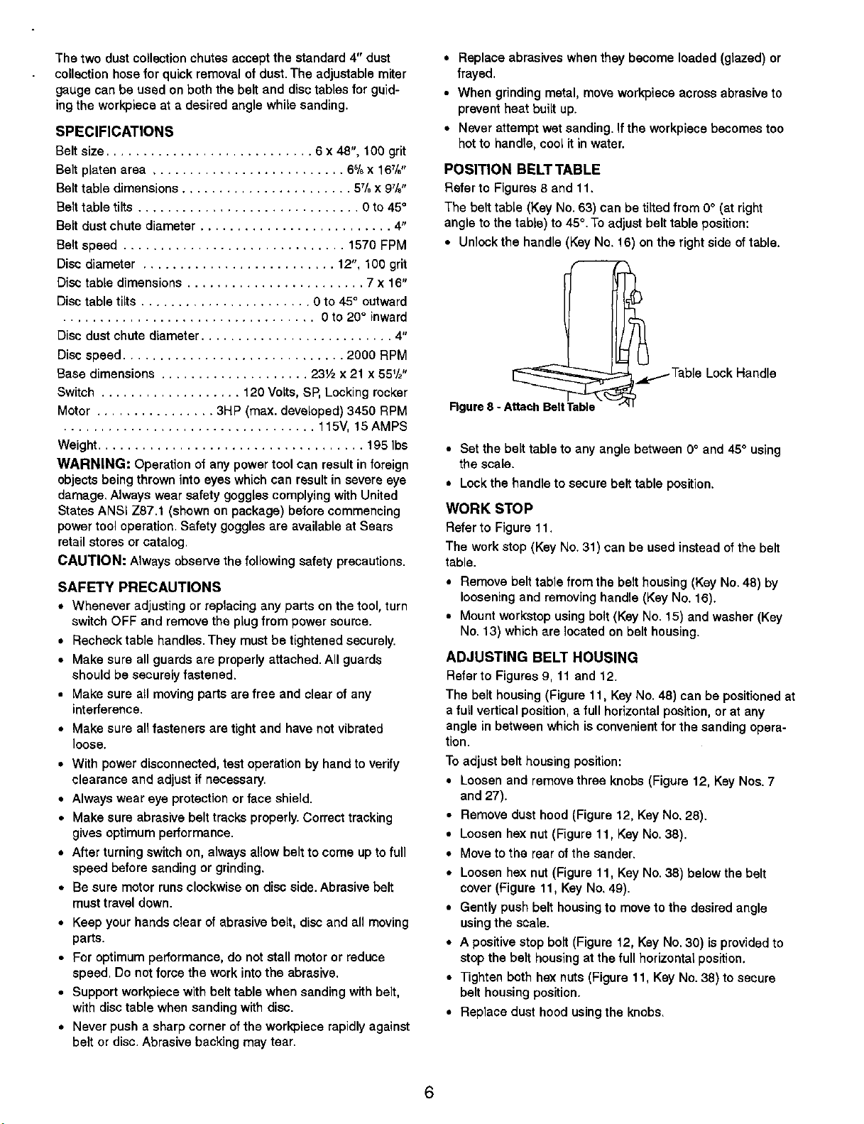
POSITION BELT TABLE
Refer to Figures 8 and 11.
The belt table (Key No. 53) can be tilted from 0° (at right
angle to the table) to 45°.To adjust belt table position:
• Unlock the handle (Key No. 18) on the right side of table.
__ _.Table Lock Handle
Rgure 8 - Attach BeltTable
• Set the belt table to any angle between 0° and 45° using
the scale.
• Lock the handle to secure belt table position.
WORK STOP
Refer to Figure 11.
The work stop (Key No. 31) can be used instead of the belt
table.
• Remove belt table from the belt housing (Key No. 48) by
loosening and removing handle (Key No. 16).
• Mount workstop using bolt (Key No. 15) and washer (Key
No. 13) which are located on belt housing.
ADJUSTING BELT HOUSING
Refer to Figures 9, 11 and 12.
The belt housing (Figure 11, Key No. 48) can be positioned at
a full vertical position, a full horizontal position, or at any
angle in between which isconvenient for the sanding opera-
tion.
To adjust belt housing position:
• Loosen and remove three knobs (Figure 12, Key Nos. 7
and 27).
• Remove dust hood (Figure 12, Key No. 28).
• Loosen he)( nut (Figure 11, Key No. 38).
• Move to the rear of the sander.
• Loosen hex nut (Figure 11, Key No. 38) below the belt
cover (Figure 11, Key No. 49).
• Gently push belt housing to move to the desired angle
using the soale.
• A positive stop bolt (Figure t2, Key No. 30) is provided to
stop the belt housing at the full horizontal position.
• Tighten both hex nuts (Figure 11, Key No. 38) to secure
belt housing position.
• Replace dust hood usingthe knobs.
6
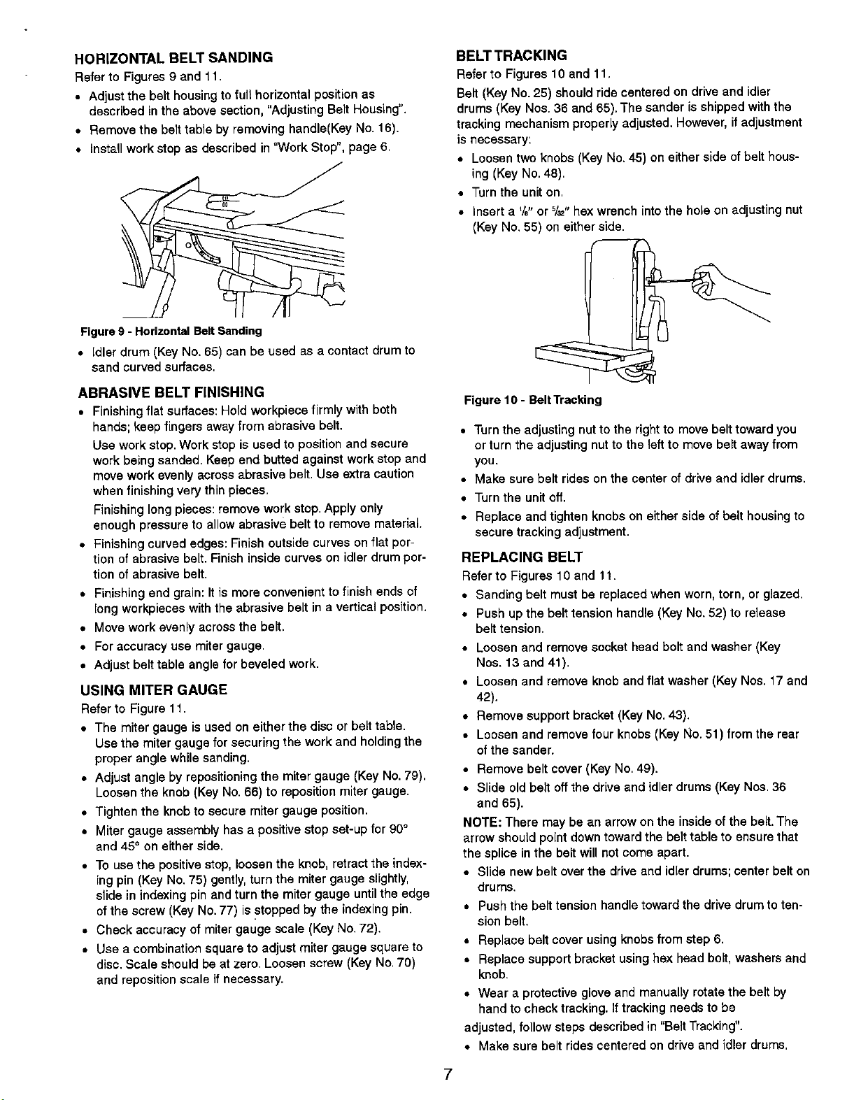
HORIZONTAL BELT SANDING
Refer to Figures 9 and lt.
• Adjust the belt housing to full horizontal position as
described in the above section, "Adjusting Belt Housing".
• Remove the belt table by removing handle(Key No. 16).
• Install work stop as described in "Work Stop", page 6,
Figure g - Horizontal BeltSending
• Idler drum (Key No, 65) can be used as a contact drum to
sand curved surfaces.
BELT TRACKING
Refer to Figures 10 and 11,
Belt (Key No. 25) should ride centered on drive and idler
drums (Key Nos. 36 and 65). The sander is shipped with the
tracking mechanism properly adjusted. However, if adjustment
is necessary:
• Loosen two knobs (Key No. 45) on either side of belt hous-
ing (Key No. 48).
• Turn the unit on,
• Insert a '/8"or 5/_,,he:<wrench into the hole on adjusting nut
(Key No. 55) on either side.
ABRASIVE BELT FINISHING
• Finishing flat surfaces: Hold workpiece firmly with both
hands; keep fingers away from abrasive belt.
Use work stop. Work stop is used to position and secure
work being sanded. Keep end butted against work stop and
move work evenly across abrasive belt. Use extra caution
when finishing very thin pieces,
Finishing long pieces: remove work stop. Apply only
enough pressure to allow abrasive belt to remove material.
• Finishing curved edges: Finish outside curves on flat por-
tion of abrasive belt. Finish inside curves on idler drum por-
tion of abrasive belt.
• Finishing end grain: It is more convenient to finish ends of
long wor_ieces with the abrasive belt in a vertical position.
• Move work evenly across the bait.
• For accuracy use miter gauge.
• Adjust belt table angle for beveled work.
USING MITER GAUGE
Refer to Figure 11.
• The miter gauge is used on either the disc or belt table.
Use the miter gauge for securing the work and holding the
proper angle while sanding.
• Adjust angle by repositioning the miter gauge (Key No. 79),
Loosen the knob (Key No. 66) to reposition miter gauge.
• Tighten the knob to secure miter gauge position.
• Miter gauge assembly has a positive stop set-up for 90°
and 45° on either side.
• To use the positive stop, loosen the knob, retract the index-
ing pin (Key No. 75) gently, turn the miter gauge slightly,
slide in indexing pin and turn the miter gauge until the edge
of the screw (Kay No. 77) is stopped by the indexing pin.
• Check accuracy of miter gauge scale (Key No. 72).
• Use a combination square to adjust miter gauge square to
disc. Scale should be at zero. Loosen screw (Key No. 70)
and reposition scale if necessary.
Figure 10 - BeltTracking
• Turn the adjusting nut to the right to move belt toward you
or turn the adjusting nut to the left to move belt away from
you.
• Make sure belt rides on the center of drive and idler drums.
• Turn the unit off.
• Replace and tighten knobs on either side of belt housing to
secure tracking adjustment.
REPLACING BELT
Refer to Figures 10 and 11.
• Sanding belt must be replaced when worn, torn, or glazed.
• Push up the belt tension handle (Key No. 52) to release
belt tension.
• Loosen and remove socket head bolt and washer (Key
Nos. 13 and 41).
• Loosen and remove knob and flat washer (Key Nos. 17 and
42).
• Remove support bracket (Key No. 43).
• Loosen and remove four knobs (Key No. 51) from the rear
of the sander.
• Remove belt cover (Key No. 49).
• Slide old belt off the drive and idler drums (Key Nos. 36
and 65).
NOTE: There may be an arrow on the inside of the belt. The
arrow should point down toward the belt table to ensure that
the splice in the belt will not come apart.
• Slide new belt over the drive and idler drums; center belt on
drums.
• Push the belt tension handle toward the drive drum to ten-
sion belt.
• Replace belt cover using knobs from step 6.
• Replace support bracket using hex head bolt, washers and
knob.
• Wear a protective glove and manually rotate the belt by
hand to check tracking. If tracking needs to be
adjusted, follow steps described in "Belt Tracking".
• Make sure belt rides centered on drive and idler drums,
7
POSITION DISC TABLE
Refer to Figure 11.
• Disc table (Key No. 24) is adjustable from 0° to 45= out-
ward and 0° to 20° inward.
• To adjust the disc table position, loosen the two handles
(KeyNo. 16) from either side of the disc table.
• Use the scale on disc table trunnions to set table at the
desired angle.
• Secure disc table position by tightening the two handles.
ABRASIVE DISC FINISHING
• Abrasive disc sanding is well suited for finishing small flat
surfaces and convex edges,
• Move workpiece across down side (right) of abrasive disc.
• Abrasive disc moves fastest and removes more material at
outer edge.
• For accuracy, use miter gauge.
REPLACING ABRASIVE DISC
Refer to Figures 11 and 12.
• Loosen and remove four bolts (Figure 11, Key No. 4) from
disc cover plate (Figure 11, Key No. 3).
• Loosen two top bolts (Figure 12, Key No. 22) from dust col-
lection port (Figure 12, Key No. 21).
• Remove disc cover plate.
• Remove old abrasive by peeling itfrom the aluminum disc.
Removing aluminum disc is not necessary.
• Clean aluminum disc if necessary. Select the proper abra-
sive disc and apply to aluminum disc.
• Additional abrasive discs are available (See Recommended
Accessories, page 11).
• Replace disccover plate
• Tighten bolts on dust collection port.
• Replace four bolts to secure disc cover plate.
WARNING: Make certain that the unit is disconnected from
power soume before attempting to service or remove any
component,
REPLACING V-BELT
Refer to Figures 11 and 12.
• Turn sander off and disconnect it from power source.
• Loosen and remove two handles (Figure 11, Key No. 16)
from either side of the disc table (Figure 11, Key No. 24).
• Slide out disc table from the disc guard (Figure 11, Key No.
11).
• Loosen the set screw (Figure 11, Key No. 2) securing the
aluminum disc (Figure 11, Key No. 1). Use the hole on the
top of disc guard to locate and loosen set screw. Do not
remove set screw.
= Loosen and remove four bolts (Figure 11, Key No. 4) from
disc cover plate.
• Loosen and remove four bolts (Figure 12, Key No. 22) from
dust collection port (Figure 12, Key No. 21).
• Remove disc cover plate and dust collection port.
• Slide out and remove aluminum disc.
• Loosen and remove knob (Figure 12, Key No. 7) from cabi-
net door assembly (Figure 12, Key No. 8).
• Open cabinet door.
• Turn knob (Figure 12, Key No. 7) on bracket (Figure 12,
Key No. 17) to release tension on V-beif (Figure 11, Key
No. 6).
• Replace V-belt. Use parts list to order the appropriate V-
belt.
• Tighten knob on bracket to tension the V-belt.
• Do not over tension the V-belt. Excessive tension on V-belt
will reduce life of the belt and function of the tooL. A belt is
properly tensioned when light pressure applied to midpoint
of the belt produces about 1/2" deflection.
• Close the cabinet door and secure it with the knob.
• Replace aluminum disc and secure it by tightening the set
screw.
• Replace dust collection port and disc cover plate and
secure itwith bolts.
• Replace disc table onto the disc guard and secure it using
the two handles.
CLEANING
Keep machine and workshop clean. Do not allow sawdust to
accumulate on the tool. Keep the drums clean. Dirt on drums
will cause poor tracking and belt slippage. Operate tool with
dust collector to keep dust from accumulating.
WARNING: After sanding wood or nonmetallic material,
always clean dust collector and guards of sawdust before
grinding metal. Sparks could ignite debris and cause a fire.
Be certain motor is kept clean and isfrequently vacuumed
free of dust.
Use soap and water to clean painted parts, rubber parts and
plastic guards.
LUBRICATION
The shielded ball bearings in this tool are permanently lubri-
cated at the factory. They require no further lubrication.
• When operation seems stiff, a lightcoat of automobile-type
wax applied to the belt and disc tables will make it easier to
feed the work while finishing.
• Do not apply wax to the belt platen. Belt could pick up wax
and deposit it on the drums causing belt to slip.
KEEPTOOL IN REPAIR
• Ifpowercordisworn,cut,or damagedin anyway,haveit
replacedimmediately.
• Replacewornabrasiveswhen needed.
• Replaceany damagedor missingparts.Usepartslist to
orderparts.
Any attemptto repairmotormay createa hazardunless
repairisdonebya qualifiedservicetechnician.Repairservice
isavailable at yournearestSearsstore.
8
 Loading...