

Craftsman 351225950 Owner’s Manual

Operator's Manual
CRAFTSMAN+
6 x 48" Belt
9" Disc
SANDER/GRINDER WITH
Model No.
351.225950
STAND
CAUTION: Read and follow
all Safety Rules and Operating
Instructions before First Use
of this Product.
Sears, Roebuck and Co., Hoffman Estates, IL 60179 U.S.A.
2087.00 Draft (06/30/98)
Warranty ....................................... 2
Safety Rules .................................... 2
Unpacking ..................................... 3
Assembly ..................................... 3-4
Installation .................................... 4-5
Operation .................................... 5-7
Maintenance .................................... 7
Troubleshooting ................................. 8
Parts Illustration and List ........................ 9-11
Espa_ol .................................... 12-19
FULL ONE YEAR WARRANTY ON CRAFTSMAN
BELT & DISC SANDER/GRINDER
If within one full year from the date of purchase, this
Craftsman sander/grinder fails due to a defect in material or
workmanship, Sears will repair it free of charge. Warranty ser-
vice is available by contacting Sears in-home major brand
repair service.This warranty gives you specific legal rights and
you may also have other rights which vary from state to state.
If this sander/grinder is used for commercial purposes, this
warranty applies for only 90 days from the date of purchase.
Sears, Roebuck and Co., Dept. 817WA, Hoffman Estates, IL
60179
WARNING: For your own safety, read all of the instructions
and precautions before operating tool.
CAUTION: Always follow proper operating procedures as
defined in this manual even if you are familiar with use of this
or similar tools. Remember that being careless for even a
fraction of a second can result in severe personal injury.
BE PREPARED FOR JOB
• Wear proper apparel. Do not wear loose clothing, gloves,
neckties, rings, bracelets or other jewelry which may get
caught in moving parts of machine.
• Wear protective hair covering to contain long hair.
• Wear safety shoes with non-slip soles.
• Wear safety glasses complying with United States ANSI
Z87.1. Everyday glasses have only impact resistant lenses.
They are NOT safety glasses.
• Wear face mask or dust mask if operation is dusty.
• Be alert and think clearly. Never operate power tools when
tired, intoxicated or when taking medications that cause
drowsiness.
PREPARE WORK AREA FOR JOB
, Keep work area clean. Cluttered work areas invite accidents.
, Do not use power tools in dangerous environments. Do not
use power tools in damp or wet locations. Do not expose
power tools to rain.
, Work area should be properly lighted.
• Proper electrical receptacle should be available for tool.
Three prong plug should be plugged directly into properly
grounded, three-prong receptacle.
• Extension cords should have a grounding prong and the three
wires of the extension cord should be of the correct gauge.
• Keep visitors at a safe distance from work area.
• Keep children out of workplace. Make workshop childproof.
Use padlocks, master switches or remove switch keys to
prevent any unintentional use of power tools.
TOOL SHOULD BE MAINTAINED
• Always unplug tool prior to inspection.
• Consult manual for specific maintaining and adjusting
procedures.
• Keep tool lubricated and clean for safest operation.
• Remove adjusting tools. Form habit of checking to see that
adjusting tools are removed before switching machine on.
• Keep all parts in working order. Check to determine that the
guard or other parts will operate properly and perform their
intended function.
• Check for damaged parts. Check for alignment of moving
parts, binding, breakage, mounting and any other condition
that may affect a tool's operation.
• A guard or other part that is damaged should be properly
repaired or replaced. Do not perform makeshift repairs.
(Use parts list provided to order replacement parts.)
KNOW HOW TO USE TOOL
• Use right tool for job. Do not force tool or attachment to do
a job for which it was not designed.
• Disconnect tool when changing belt or abrasive disc.
• Avoid accidental start-up. Make sure that the tool is in the
"OFF" position before plugging in.
• Do not force tool. It will work most efficiently at the rate for
which it was designed.
• Keep hands away from moving parts and sanding surfaces.
• Never leave tool running unattended. Turn the power off
and do not leave tool until it comes to a complete stop.
• Do not overreach. Keep proper footing and balance.
• Never stand on tool. Serious injury could occur if tool is
tipped or if belt or disc are unintentionally contacted.
• Know your tool. Learn the tool's operation, application and
specific limitations.
• Use recommended accessories (refer to page 11). Use of
improper accessories may cause risk of injury to persons.
• Handle the workpiece correctly. Protect hands from possi-
ble injury.
• Turn machine off if it jams. Belt jams when it digs too
deeply into workpiece. (Motor force keeps it stuck in the
work.)
• Support workpiece with miter gauge, belt platen or work
table.
• Maintain 1/16"maximum clearance between table and sand-
ing belt or disc.
CAUTION: Think safety? Safety is a combination of operator
common sense and alertness at all times when tool is being
used.
WARNING: Do not attempt to operate tool until it is com-
pletely assembled according to the instructions.
2
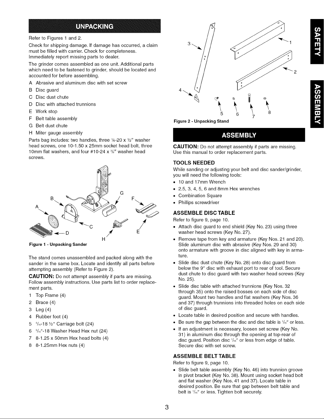
Refer to Figures 1 and 2.
Check for shipping damage. If damage has occurred, a claim
must be filled with carrier. Check for completeness.
Immediately report missing parts to dealer.
The grinder comes assembled as one unit. Additional parts
which need to be fastened to grinder, should be located and
accounted for before assembling.
A Abrasive and aluminum disc with set screw
B Disc guard
C Disc dust chute
D Disc with attached trunnions
E Work stop
F Belt table assembly
G Belt dust chute
H Miter gauge assembly
Parts bag includes: two handles, three 1A-20 x W' washer
head screws, one 10-1.50 x 25mm socket head bolt, three
lOmm flat washers, and four #10-24 x 3/8"washer head
screws.
G
B
5
6 8
7
Figure 2 - Unpacking Stand
CAUTION: Do not attempt assembly if parts are missing.
Use this manual to order replacement parts.
TOOLS NEEDED
While sanding or adjusting your belt and disc sander/grinder,
you will need the following tools:
• 10 and 17mm Wrench
• 2.5, 3, 4, 5, 6 and 8mm Hex wrenches
• Combination Square
• Phillips screwdriver
H
Figure 1 - Unpacking Sander
The stand comes unassembled and packed along with the
sander in the same box. Locate and identify all parts before
attempting assembly (Refer to Figure 2).
CAUTION: Do not attempt assembly if parts are missing.
Follow assembly instructions. Use parts list to order replace-
ment parts.
1 Top Frame (4)
2 Brace (4)
3 Leg (4)
4 Rubber foot (4)
5 8/18-18V2" Carriage bolt (24)
6 8/18"-18Washer Head Hex nut (24)
7 8-1.25 x 50mm Hex head bolts (4)
8 8-1.25mm Hex nuts (4)
ASSEMBLE DISC TABLE
Refer to figure 9, page 10.
• Attach disc guard to end shield (Key No. 23) using three
washer head screws (Key No. 27).
• Remove tape from key and armature (Key Nos. 21 and 20).
Slide aluminum disc with abrasive (Key Nos. 29 and 30)
onto armature with groove in disc aligned with key in arma-
ture.
• Slide disc dust chute (Key No. 28) onto disc guard from
below the 9" disc with exhaust port to rear of tool. Secure
dust chute to disc guard with two washer head screws (Key
No. 25).
• Slide disc table with attached trunnions (Key Nos. 32
through 35) onto the raised bosses on each side of disc
guard. Mount two handles and flat washers (Key Nos. 36
and 37) through trunnions into threaded holes on each side
of disc guard.
• Locate table in desired position and secure with handles.
• Be sure the gap between the disc and disc table is 1A8"or less.
• If an adjustment is necessary, loosen set screw (Key No.
31) in aluminum disc through the opening at top-rear of
disc guard. Position disc 1/1_"or less from edge of table.
Secure disc with set screw.
ASSEMBLE BELT TABLE
Refer to figure 9, page 10.
• Slide belt table assembly (Key No. 46) into trunnion groove
in pivot bracket (Key No. 38). Mount using socket head bolt
and flat washer (Key Nos. 41 and 37). Locate table in
desired position. Be sure that gap between belt table and
belt is 1/18"or less. Tighten bolt securely.
3
ASSEMBLE BELT DUST CHUTE
Refer to figure 9, page 10.
• Mount belt dust chute (Key No. 40) to platen using two
washer head screws (Key No. 25).
ASSEMBLE STAND
Refer to Figure 8, page 9.
Install rubber foot (Key No. 4) by pressing onto all four legs
(Key No. 3).
Attach one top frame (Key No. 1) to one pair of legs (Key
No. 3) using carriage bolts and hex nuts (Key Nos. 5 and
6). Repeat for second pair of legs.
Attach one brace (Key No. 2) to each pair of legs using car-
riage bolts and hex nuts.)
Connect the two leg sets with the two remaining top
frames. Make sure that the square holes in the legs align
with the square holes in the top frame. Also make sure that
the slots on top of the frame members are aligned at each
corner. Secure frames to legs using carriage bolts and hex
nuts.
Attach the two remaining braces by aligning the square
holes in the legs and the braces. Insert carriage bolts and
secure with hex nuts.
Refer to Figures 3, 4, 5, 6, and 8, page 4, 5 and 9.
POWER SOURCE
WARNING: Do not connect grinder to the power source until
all assembly steps have been completed.
The motor is designed for operation on the voltage and fre-
quency specified. Normal loads will be handled safely on volt-
ages not more than 10% above or below specified voltage.
Running the unit on voltages which are not within range may
cause overheating and motor burn-out. Heavy loads require
that voltage at motor terminals be no less than the voltage
specified on nameplate.
• Power supply to the motor is controlled by a single pole
locking rocker switch. Remove the key to prevent unautho-
rized use.
GROUNDING INSTRUCTIONS
WARNING: Improper connection of equipment grounding
conductor can result in the risk of electrical shock. Equipment
should be grounded while in use to protect operator from
electrical shock.
• Check with a qualified electrician if grounding instructions
are not understood or if in doubt as to whether the tool is
properly grounded.
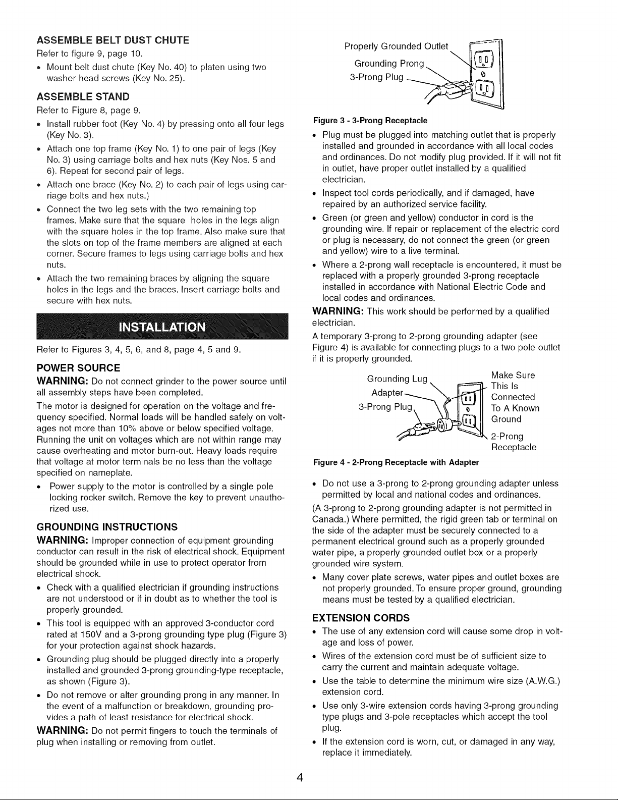
• This tool is equipped with an approved 3-conductor cord
rated at 150V and a 3-prong grounding type plug (Figure 3)
for your protection against shock hazards.
• Grounding plug should be plugged directly into a properly
installed and grounded 3-prong grounding-type receptacle,
as shown (Figure 3).
• Do not remove or alter grounding prong in any manner. In
the event of a malfunction or breakdown, grounding pro-
vides a path of least resistance for electrical shock.
WARNING: Do not permit fingers to touch the terminals of
plug when installing or removing from outlet.
Properly Grounded Outlet __=_i}
Grounding Prong.
3-Prong Plug __'__
Figure3 - 3-Prong Receptacle
• Plug must be plugged into matching outlet that is properly
installed and grounded in accordance with all local codes
and ordinances. Do not modify plug provided. If it will not fit
in outlet, have proper outlet installed by a qualified
electrician.
• Inspect tool cords periodically, and if damaged, have
repaired by an authorized service facility.
• Green (or green and yellow) conductor in cord is the
grounding wire. If repair or replacement of the electric cord
or plug is necessary, do not connect the green (or green
and yellow) wire to a live terminal.
• Where a 2-prong wall receptacle is encountered, it must be
replaced with a properly grounded 3-prong receptacle
installed in accordance with National Electric Code and
local codes and ordinances.
WARNING: This work should be performed by a qualified
electrician.
A temporary 3-prong to 2-prong grounding adapter (see
Figure 4) is available for connecting plugs to a two pole outlet
if it is properly grounded.
Grounding Lug. _ Make Sure
..._%_ This IsAdapter Connected
3-Prong Plug_ _ To A Known
Ground
2-Prong
Receptacle
Figure 4 - 2-Prong Receptacle with Adapter
• Do not use a 3-prong to 2-prong grounding adapter unless
permitted by local and national codes and ordinances.
(A 3-prong to 2-prong grounding adapter is not permitted in
Canada.) Where permitted, the rigid green tab or terminal on
the side of the adapter must be securely connected to a
permanent electrical ground such as a properly grounded
water pipe, a properly grounded outlet box or a properly
grounded wire system.
• Many cover plate screws, water pipes and outlet boxes are
not properly grounded. To ensure proper ground, grounding
means must be tested by a qualified electrician.
EXTENSION CORDS
• The use of any extension cord will cause some drop in volt-
age and loss of power.
• Wires of the extension cord must be of sufficient size to
carry the current and maintain adequate voltage.
• Use the table to determine the minimum wire size (A.W.G.)
extension cord.
• Use only 3-wire extension cords having 3-prong grounding
type plugs and 3-pole receptacles which accept the tool
plug.
• If the extension cord is worn, cut, or damaged in any way,
replace it immediately.
4
Extension Cord Length
Wire Size .................................. A.W.G.
Up to 25 ft..................................... 18
NOTE: Using extension cords over 25 ft. long is not
recommended.
MOTOR
The sander/grinder is assembled with motor and wiring
installed as an integral part of the tool. The electrical wiring
schematic is shown in Figure 5.
The 120 Volt AC permanently split capacitor motor has the fol-
lowing specifications:
Horsepower (Maximum Developed) ................. 11/2
Voltage ...................................... 120
Amperes ..................................... 8.0
Hertz ........................................ 60
Phase ..................................... Single
RPM ....................................... 3450
Rotation (viewed from left side) ............... Clockwise
ELECTRICAL CONNECTIONS
WARNING: Make sure unit is off and disconnected from
power source before inspecting any wiring.
The motor is installed and wiring connected as illustrated in
the wiring schematic (see Figure 5).
Switch_i_ Black
-o.....\ ToPower
Relay -_ "Green \,._____/_"_
FTo Motor _ S
_ Capacitor I
Figure 5 -Wiring Schematic
The motor is assembled with an approved three conductor
cord to be used on 120 volts as indicated. The power supply
to the motor is controlled by a single pole locking rocker
switch.
The power lines are inserted directly onto the switch. The
green ground line must remain securely fastened to the frame
to properly protect against electrical shock.
• Remove the key to prevent unauthorized use.
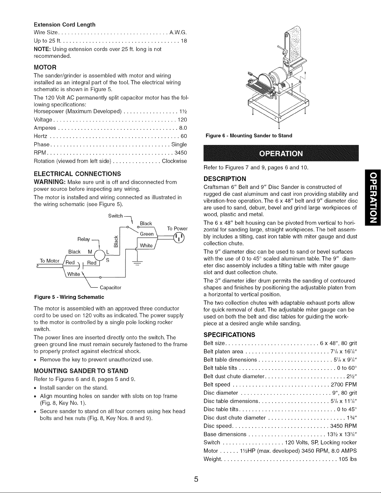
MOUNTING SANDER TO STAND
Refer to Figures 6 and 8, pages 5 and 9.
Install sander on the stand.
Align mounting holes on sander with slots on top frame
(Fig. 8, Key No. 1).
Secure sander to stand on all four corners using hex head
bolts and hex nuts (Fig. 8, Key Nos. 8 and 9).
Figure 6 - Mounting Sander to Stand
Refer to Figures 7 and 9, pages 6 and 10.
DESCRIPTION
Craftsman 6" Belt and 9" Disc Sander is constructed of
rugged die cast aluminum and cast iron providing stability and
vibration-free operation. The 6 x 48" belt and 9" diameter disc
are used to sand, deburr, bevel and grind large workpieces of
wood, plastic and metal.
The 6 x 48" belt housing can be pivoted from vertical to hori-
zontal for sanding large, straight workpieces. The belt assem-
bly includes a tilting, cast iron table with miter gauge and dust
collection chute.
The 9" diameter disc can be used to sand or bevel surfaces
with the use of 0 to 45° scaled aluminum table. The 9" diam-
eter disc assembly includes a tilting table with miter gauge
slot and dust collection chute.
The 3" diameter idler drum permits the sanding of contoured
shapes and finishes by positioning the adjustable platen from
a horizontal to vertical position.
The two collection chutes with adaptable exhaust ports allow
for quick removal of dust. The adjustable miter gauge can be
used on both the belt and disc tables for guiding the work-
piece at a desired angle while sanding.
SPECIFICATIONS
Belt size ............................. 6 x 48", 80 grit
Belt platen area .......................... 71/8x 167/8''
Belt table dimensions ....................... 57/8x 97/8''
Belt table tilts .............................. 0 to 60 °
Belt dust chute diameter ......................... 21/2''
Belt speed .............................. 2700 FPM
Disc diameter ............................ 9", 80 grit
Disc table dimensions ...................... 57/8x 117/8''
Disc table tilts .............................. 0 to 45 °
Disc dust chute diameter ........................ 13/4"
Disc speed .............................. 3450 RPM
Base dimensions ........................ 131/2x 138/8''
Switch ................... 120 Volts, SP, Locking rocker
Motor ...... 11/2HP(max. developed) 3450 RPM, 8.0 AMPS
Weight .................................... 105 Ibs
5

WARNING: Operation of any power tool can result in foreign
objects being thrown into the eyes, which can result in severe
eye damage. Always wear safety goggles complying with
United States ANSI Z87.1 (shown on package) before com-
mencing power tool operation. Safety goggles are available at
Sears retail stores or catalog.
CAUTION: Always observe following safety precautions.
SAFETY PRECAUTIONS
• Whenever adjusting or replacing any parts on the tool, turn
switch OFF and remove the plug from power source.
Recheck table handles. They must be tightened securely.
Make sure all guards are properly attached. All guards
should be securely fastened.
Make sure all moving parts are free and clear of any
interference.
Make sure all fasteners are tight and have not vibrated
loose.
With power disconnected, test operation by hand for clear-
ance and adjust if necessary.
Always wear eye protection or face shield.
Make sure abrasive belt always tracks properly. Correct
tracking gives optimum performance.
After turning switch on, always allow belt to come up to full
speed before sanding or grinding.
Be sure motor runs clockwise on disc side. Abrasive belt
must travel down.
Avoid kickback by sanding in accordance with the direction-
al arrows.
Keep your hands clear of abrasive belt, disc and all moving
parts.
For optimum performance, do not stall motor or reduce
speed. Do not force the work into the abrasive.
Support workpiece with belt table when sanding with belt,
with disc table when sanding with disc.
Never push a sharp corner of the workpiece rapidly against
the belt or disc. Abrasive backing may tear.
Replace abrasives when they become loaded (glazed) or
frayed.
When grinding metal, move workpiece across abrasive to
prevent heat built up.
Never attempt wet sanding. If the workpiece becomes too
hot to handle, cool it in water.
REPLACING ABRASIVE BELT
Refer to Figure 9, page10.
• Sanding belt should be replaced when worn, torn, or
glazed. Remove belt dust chute (Key No. 40) by removing
two washer head screws (Key No. 25).
• Release belt tension by pushing tension lever (Key No. 63)
toward idler drum. Slide old belt off the drive and idler
drums (Key Nos. 52 and 66).
NOTE: There may be an arrow on the inside of the belt. The
arrow should point down toward the belt table to ensure that
the splice in the belt will not come apart.
• Slide new belt over the drive and idler drums; center belt on
drums.
• Push tension lever towards drive drum to tension belt.
Rotate belt by hand to check tracking. Belt should ride cen-
tered on drive and idler drums. Adjust thumb nut (Key No.
75) as needed to center belt on drums. Tighten hex nut
(Key No. 39). If adjustment of thumb nut does not provide
desirable tracking, adjust the stud (Key No. 72) using an
allen wrench. To adjust stud, loosen hex nut (Key No. 39)
and turn stud counterclockwise to move belt to the right or
clockwise to move belt to the left until belt rides centered
on drive and idler drums. Tighten hex nut while holding the
stud in place.
Mount belt dust chute using washer head screws.
ADJUSTING BELT ASSEMBLY POSITION
Refer to Figure 9, page 10.
Sanding belt assembly can be adjusted from horizontal to ver-
tical position.
• Loosen socket head bolt (Key No. 54) that is threaded into
pivot bracket (Key No. 38).
• Tilt belt assembly to desired position (from horizontal to
vertical). Secure belt assembly position by tightening socket
head bolt in pivot bracket.
ADJUSTING BELT TABLE
Refer to Figure 9, page 10.
• To adjust belt table angle, loosen socket head bolt
(Key No. 41 ).
• Tilt belt table to desired position. Adjust for 1/1_"maximum
clearance between the belt and the table. Secure by tight-
ening socket head bolt.
HORIZONTAL BELT SANDING
Refer to Figure 9, page 10.
• The belt platen can be tilted from a vertical to a horizontal
position.
• Remove the belt table by removing the socket head bolt
and flat washer (Key Nos. 41 and 37). Loosen the socket
head bolt (Key No. 54); tilt the belt platen assembly to the
horizontal position and tighten the socket head bolt to
secure position.
• Idler drum can be used as a contact drum to sand sur-
faces.
WORK STOP
Refer to Figure 9, page 10.
The work stop (Key No 42) can be used instead of the belt
table.
• Remove socket head bolt and flat washer (Key Nos. 41 and
37) holding belt table on pivot bracket. Remove belt table.
• Mount work stop to pivot bracket using the socket head bolt
and washer (Key Nos. 41 and 37).
SHARPENING
Refer to Figure 7, page 7.
Adjust belt table to desired sharpening angle and tighten
securely. Use belt sander/grinder to notch the back of an
auxiliary piece of wood.
Using a C-clamp, attach auxiliary piece of wood to table. It
acts as a support while sharpening (see Figure 7).
Top edge of wood should be less than 1/1_"from abrasive
belt.
6
 Loading...