

Craftsman 351225000 Owner’s Manual

Operator's Manual
CP.RFTSMRN°
6 x 48" Belt, 9" Disc
SANDER
Model No.
351.225000
CAUTION: Read and follow
all Safety Rules and Operating
Instructions before First Use
of this Product. Keep this
manual with tool.
Sears, Roebuck and Co., Hoffman Estates, IL 60179 U.S.A.
www.sears.com/craftsman
30664.00 Draft (04/14/09)

Warranty ......................................... 2
Safety Rules .................................... 2-3
Unpacking ....................................... 3
Assembly ...................................... 3-4
Installation ...................................... 4-5
Operation ...................................... 5-8
Maintenance .................................... 8-9
Troubleshooting ................................... 9
Parts Illustration and List ........................ 12-15
Espa_ol ...................................... 16-27
ONE-YEAR FULL WARRANTY ON CRAFTSMAN
TOOL
If this Craftsman tool fails due to a defect in material or work-
manship within one year from the date of purchase, call 1-
800-4-MY-HOME® TO ARRANGE FOR FREE REPAIR (or
replacement if repair proves impossible). This warranty does
not include expendable parts, such as lamps, batteries, bits or
blades.
If this tool is ever used for commercial or rental purposes, this
warranty will apply for only 90 days from the date of purchase.
This warranty gives you specific legal rights and you may also
have other rights which vary from state to state.
Sears, Roebuck and Co., Hoffman Estates, IL 60179
WARNING: For your own safety, read all of the instructions
and precautions before operating tool.
PROPOSITION 65 WARNING: Some dust created by
power sanding, sawing, grinding, drilling and other construc-
tion activities contains chemicals known to the state of
California to cause cancer, birth defects or other reproductive
harm.
Some examples of these chemicals are:
• Lead from lead-based paints.
• Crystalline silica from bricks and cement and other
masonry products.
• Arsenic and chromium from chemically-treated lumber.
Your risk from these exposures vary, depending on how often
you do this type of work. To reduce your exposure to these
chemicals: work in a well ventilated area and work with
approved safety equipment. Always wear OSHA/NIOSH
approved, properly fitting face mask or respirator when using
such tools.
CAUTION: Always follow proper operating procedures as
defined in this manual even if you are familiar with use of this
or similar tools. Remember that being careless for even a
fraction of a second can result in severe personal injury.
BE PREPARED FOR JOB
• Wear proper apparel. Do not wear loose clothing, gloves,
neckties, rings, bracelets or other jewelry which may get
caught in moving parts of machine.
• Wear protective hair covering to contain long hair.
• Wear safety shoes with non-slip soles.
• Wear safety glasses complying with United States ANSI
Z87.1. Everyday glasses have only impact resistant lenses.
They are NOT safety glasses.
• Wear face mask or dust mask if operation is dusty.
• Be alert and think clearly. Never operate power tools when
tired, intoxicated or when taking medications that cause
drowsiness.
PREPARE WORK AREA FOR JOB
• Keep work area clean. Cluttered work areas invite accidents.
• Do not use power tools in dangerous environments. Do not
use power tools in damp or wet locations. Do not expose
power tools to rain.
• Work area should be properly lighted.
• Proper electrical receptacle should be available for tool.
Three-prong plug should be plugged directly into properly
grounded, three-prong receptacle.
• Extension cords should have a grounding prong and the three
wires of the extension cord should be of the correct gauge.
• Keep visitors at a safe distance from work area.
• Keep children out of workplace. Make workshop childproof.
Use padlocks, master switches or remove switch keys to
prevent any unintentional use of power tools.
TOOL SHOULD BE MAINTAINED
• Always unplug tool prior to inspection.
• Consult manual for specific maintaining and adjusting
procedures.
• Keep tool lubricated and clean for safest operation.
• Remove adjusting tools. Form habit of checking to see that
adjusting tools are removed before switching machine on.
• Keep all parts in working order. Check to determine that the
guard or other parts will operate properly and perform their
intended function.
• Check for damaged parts. Check for alignment of moving
parts, binding, breakage, mounting and any other condition
that may affect a tool's operation.
• A guard or other part that is damaged should be properly
repaired or replaced. Do not perform makeshift repairs.
(Use parts list provided to order replacement parts.)
KNOW HOW TO USE TOOL
• Use right tool for job. Do not force tool or attachment to do
a job for which it was not designed.
• Disconnect tool when changing belt or abrasive disc.
• Avoid accidental start-up. Make sure that the tool is in the
"OFF" position before plugging in.
• Do not force tool. It will work most efficiently at the rate for
which it was designed.
• Keep hands away from moving parts and sanding surfaces.
• Never leave tool running unattended. Turn the power off
and do not leave tool until it comes to a complete stop.
• Do not overreach. Keep proper footing and balance.
• Never stand on tool. Serious injury could occur if tool is
tipped or if belt or disc are unintentionally contacted.
• Know your tool. Learn the tool's operation, application and
specific limitations.
• Use recommended accessories (refer to page 15). Use of
improper accessories may cause risk of injury to persons.
© Sears, Roebuck and Co. 2

• Handle the workpiece correctly. Protect hands from possi-
ble injury.
• Turn machine off if it jams. Belt jams when it digs too
deeply into workpiece. (Motor force keeps it stuck in the
work.)
• Support workpiece with miter gauge, belt platen or work
table.
• Maintain 1/16"maximum clearance between table and sand-
ing belt or disc.
CAUTION: Think safety! Safety is a combination of operator
common sense and alertness at all times when tool is being
used.
WARNING: Do not attempt to operate tool until it is com-
pletely assembled according to the instructions.
Refer to Figure 1.
Check for shipping damage. If damage has occurred, a claim
must be filled with carrier. Check for completeness.
Immediately report missing parts to dealer.
The sander comes assembled as one unit. Additional parts
which need to be fastened to sander, should be located and
accounted for before assembling.
A Sander
B Miter Gauge Assembly
C Support Rod
D Table Assembly
Hardware Bag (Not Shown)
A
MOUNT SANDER
Refer to Figure 2.
NOTE: Although compact, the sander is heavy. At least two
people are required to lift from carton.
Choose a suitable location to mount the sander. The sander
must be installed in a place with ample lighting and correct
power supply. To install sander:
• The sander must be bolted to a firm, level surface.
• Make sure there is plenty of room for moving the work-
piece. There must be enough room that neither operators
nor bystanders will have to stand in line with the wood
while using the tool. Allow room so that belt assembly can
be positioned horizontally.
• Sander can be installed on a workbench or a tool stand
using bolts, lock washers and hex nuts (not supplied).
• Figure 2 shows the base dimensions, mounting holes and
required space to allow for table assembly and belt
assembly in horizontal position.
3/8"Dia.
/o
171/2''
1 9 _r
30 rr
D
Figure 1 - Unpacking Sander
Refer to Figures 2, 3 and 4.
CAUTION: Do not attempt assembly if parts are missing.
Use this manual to order replacement parts.
WARNING: Do not operate machine until completely assem-
bled. Do not operate machine until you have completely read
and understood this manual.
TOOLS NEEDED
While assembling or adjusting your belt and disc sander, you
will need the following tools:
• 10mm Wrench
• 5 and 6mm Hex Wrenches
• Combination Square
• Phillips Screwdriver
L 71/2" ,,...,_
12"
Figure 2 - Base Dimension and Required Space
ATTACH TABLE ASSEMBLY
Refer to Figures 3 and 4, page 4.
The included table assembly is used with both the disc and
belt.
To use the table with the disc:
• Insert table support rod into sander base. Secure using bolt
(A), make sure bolt tightens onto the flat surface of the rod.
• Position table assembly on support rod so that gap
between table and disc is 1/16"or less. Secure table in
position with bolt (B).
• Loosen knob. Using a combination square, set the table
perpendicular to the disc, and secure in position. If
necessary, set pointer at 0°.
3

B_it(B)
Refer to Figures 5 and 6, pages 4 and 5.
POWER SOURCE
WARNING: Do not connect sander to the power source until
all assembly steps have been completed.
Connect sander to a supply circuit protected by a circuit
breaker or time-delay fuse.
The motor is designed for operation on the voltage and fre-
quency specified. Normal loads will be handled safely on volt-
ages not more than 10% above or below specified voltage.
Running the unit on voltages which are not within range may
cause overheating and motor burn-out. Heavy loads require
that voltage at motor terminals be no less than the voltage
specified on nameplate.
• Power supply to the motor is controlled by a single pole
locking rocker switch. Remove the key to prevent unautho-
rized use.
Figure 3 - Using Table with Disc
To use the table with the belt:
• Loosen bolt in pivot bracket. (see Adjusting Belt Assembly
Position, page 6). Move belt assembly to the vertical posi-
tion, and secure in position by tightening bolt.
• Insert table support rod into the belt assembly bracket.
Secure using bolt (A), making sure bolt tightens onto the
flat surface of the rod.
• Position table assembly on support rod so that gap
between table and belt is 1/16"or less. Secure table in
position with bolt (B).
• Loosen knob. Using a combination square, set the table
perpendicular to the belt and secure in position. If
necessary, set pointer at 0°.
(B)
Figure 4 - Using Table with the Belt
GROUNDING INSTRUCTIONS
WARNING: Improper connection of equipment grounding
conductor can result in the risk of electrical shock. Equipment
should be grounded while in use to protect operator from
electrical shock.
• Check with a qualified electrician if grounding instructions
are not understood or if in doubt as to whether the tool is
properly grounded.
• This tool is equipped with an approved 3-conductor cord
rated at 150V and a 3-prong grounding type plug (Figure 5)
for your protection against shock hazards.
• Grounding plug should be plugged directly into a properly
installed and grounded 3-prong grounding-type receptacle,
as shown (Figure 5).
Properly
Figure 5 - 3-Prong Receptacle
° Do not remove or alter grounding prong in any manner. In
the event of a malfunction or breakdown, grounding pro-
vides a path of least resistance for electrical shock.
WARNING: Do not permit fingers to touch the terminals of
plug when installing or removing from outlet.
• Plug must be plugged into matching outlet that is properly
installed and grounded in accordance with all local codes
and ordinances. Do not modify plug provided. If it will not fit
in outlet, have proper outlet installed by a qualified electrician.
• Inspect tool cords periodically, and if damaged, have
repaired by an authorized service facility.
• Green (or green and yellow) conductor in cord is the
grounding wire. If repair or replacement of the electric cord
or plug is necessary, do not connect the green (or green
and yellow) wire to a live terminal.
• Where a 2-prong wall receptacle is encountered, it must be
replaced with a properly grounded 3-prong receptacle
installed in accordance with National Electric Code and
local codes and ordinances.
WARNING: This work should be performed by a qualified
electrician.
3-Prong Plug _'__
Grounded Outlet
Grounding Prong
4

A temporary 3-prong to 2-prong grounding adapter (see
Figure 6) is available for connecting plugs to a two pole outlet
if it is properly grounded.
Grounding Lug.
Adapter.-.._%_
3-ProngP_. _
Figure 6 - 2-Prong Receptacle with Adapter
• Do not use a 3-prong to 2-prong grounding adapter unless
permitted by local and national codes and ordinances.
(A 3-prong to 2-prong grounding adapter is not permitted in
Canada.) Where permitted, the rigid green tab or terminal on
the side of the adapter must be securely connected to a
permanent electrical ground such as a properly grounded
water pipe, a properly grounded outlet box or a properly
grounded wire system.
• Many cover plate screws, water pipes and outlet boxes are
not properly grounded. To ensure proper ground, grounding
means must be tested by a qualified electrician.
EXTENSION CORDS
• The use of any extension cord will cause some drop in
voltage and loss of power.
• Wires of the extension cord must be of sufficient size to
carry the current and maintain adequate voltage.
• Use the table to determine the minimum wire size (A.W.G.)
extension cord.
• Use only 3-wire extension cords having 3-prong grounding
type plugs and 3-pole receptacles which accept the tool
plug.
• If the extension cord is worn, cut, or damaged in any way,
replace it immediately.
Extension Cord Length
Wire Size ................................... A.W.G.
Up to 25 ft....................................... 18
25 to 50 ft....................................... 16
NOTE: Using extension cords over 50 ft. long is not
recommended.
Make Sure
This Is
Connected
To A Known
Ground
2-Prong
Receptacle
MOTOR
The sander is assembled with motor and wiring installed.
225000 MOTOR SPECIFICATIONS:
Horsepower (Continuous Duty) ....................... 3/4
Voltage ........................................ 120
Amp ........................................... 8.0
Hertz .......................................... 60
Phase ....................................... Single
RPM ......................................... 3450
ELECTRICAL CONNECTIONS
WARNING: All electrical connections must be performed by
a qualified electrician. Make sure tool is off and disconnected
from power source while motor is mounted, connected, recon-
nected or anytime wiring is inspected.
Motor is assembled with approved, 3-conductor cord to be
used at 120 volts.
The power lines are inserted directly onto the switch. The
green ground line must remain securely fastened to the frame
to properly protect against electrical shock. The power supply
to the motor is controlled by a single pole locking rocker
switch.
• Remove the key to prevent unauthorized use.
Refer to Figures 7 - 16.
DESCRIPTION
The Craftsman Belt and Disc Sanders are constructed of
rugged die cast aluminum and cast iron providing stability and
vibration-free operation. The belt and disc are used to sand,
deburr, bevel and grind large workpieces of wood and plastic.
The belt housing can be pivoted from vertical to
horizontal for sanding large, straight workpieces. The idler
drum permits the sanding of contoured shapes and finishes.
The disc can be used to sand or bevel surfaces.
The adjustable miter gauge can be used on both the belt and
disc tables for guiding the workpiece at a desired angle while
sanding. Dust shroud has been designed to function as a
work stop for sanding long pieces on the belt.
SPECIFICATIONS
MODEL 225000
Belt size .................................... 6 x 48"
Belt platen area ............................. 6 x 131/2"
Belt speed ................................ 2400 FPM
Disc diameter .................................... 9"
Disc speed ............................... 3100 RPM
Table dimensions ............................. 7 x 10"
Table tilts ................................... 0 to 45 °
Dust port diameter ................................ 2"
Base dimensions ............................ 12 x 19"
Switch ............................. SP, Locking rocker
Weight ...................................... 88 Ibs
Shipping Weight ............................... 93 Ibs
WARNING: Operation of any power tool can result in foreign
objects being thrown into the eyes, which can result in severe
eye damage. Always wear safety goggles complying with
United States ANSI Z87.1 (shown on package) before com-
mencing power tool operation. Safety goggles are available at
Sears retail stores or catalog.
CAUTION: Always observe following safety precautions.
SAFETY PRECAUTIONS
• Whenever adjusting or replacing any parts on the tool, turn
switch OFF and remove the plug from power source.
• Recheck table knob and bolts. They must be tightened
securely.
• Make sure all guards are properly attached. All guards
should be securely fastened.
• Make sure all moving parts are free and clear of any
interference.
• Make sure all fasteners are tight and have not vibrated loose.
• With power disconnected, test operation by hand for clear-
ance and adjust if necessary.
• Always wear eye protection or face shield.
5
• Make sure abrasive belt always tracks properly. Correct
tracking gives optimum performance.
• After turning switch on, always allow belt and disc to come
up to full speed before sanding or grinding.
• Be sure disc turns counterclockwise. Abrasive belt must
travel downward.
• Avoid kickback by sanding in accordance with the direction-
al arrows.
• Keep your hands clear of abrasive belt, disc and all moving
parts.
• For optimum performance, do not stall motor or reduce
speed. Do not force the work into the abrasive.
• Always support workpiece with table or work stop when
sanding with belt and with table when sanding with disc.
• Never push a sharp corner of the workpiece rapidly against
the belt or disc. Abrasive backing may tear.
• Replace abrasives when they become loaded (glazed) or
frayed.
ON/OFF SWITCH
Refer to Figure 7.
The ON/OFF switch is located on the upper front right of the
cabinet. To turn the sander ON, pull the switch to the up
position. To turn the sander OFF, push the switch to the down
position.
The sander can be locked from unauthorized use by locking
the switch. To lock the switch:
= Turn the switch to OFF position and disconnect sander
from power source.
= Pull the key out. The switch cannot be turned on with the
key removed.
NOTE: Should the key be removed from the switch at the ON
position, the switch can be turned off but cannot be turned on
again.
= To replace key, slide key into the slot on switch until it snaps.
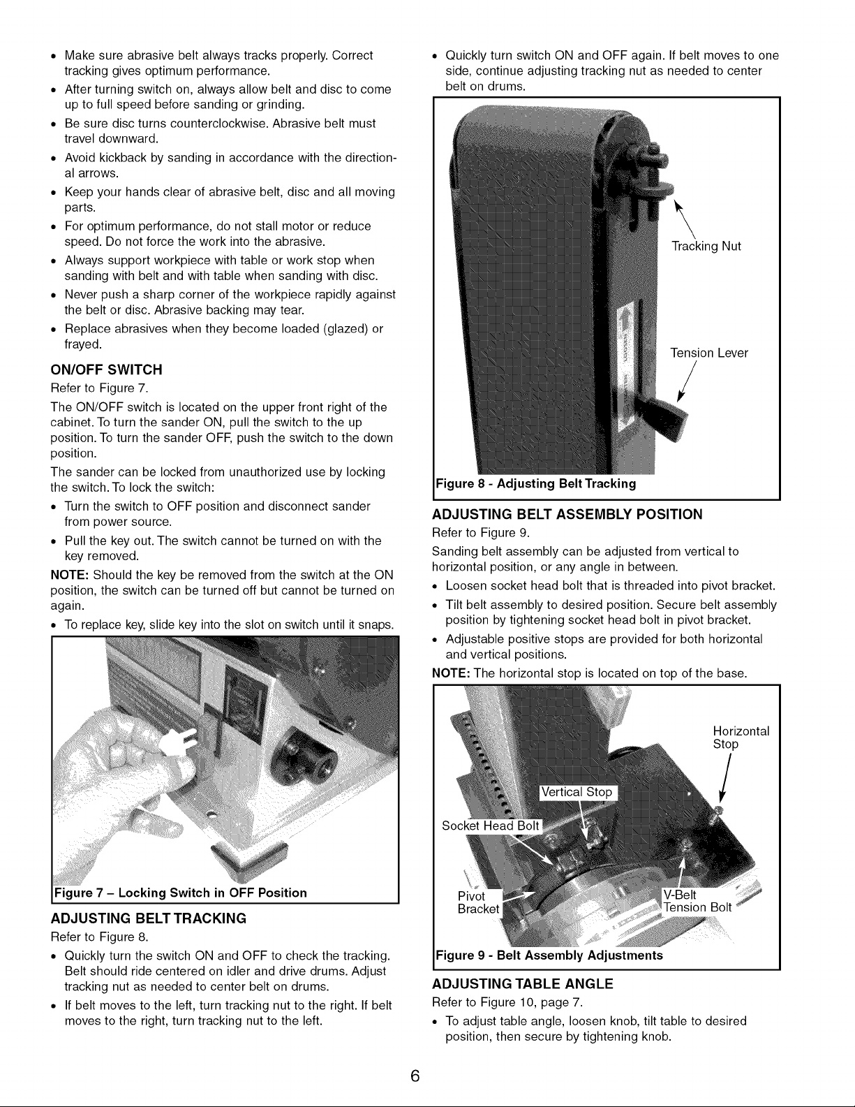
• Quickly turn switch ON and OFF again. If belt moves to one
side, continue adjusting tracking nut as needed to center
belt on drums.
\
Tracking Nut
Tension Lever
/
Figure 8 - Adjusting Belt Tracking
ADJUSTING BELT ASSEMBLY POSITION
Refer to Figure 9.
Sanding belt assembly can be adjusted from vertical to
horizontal position, or any angle in between.
• Loosen socket head bolt that is threaded into pivot bracket.
• Tilt belt assembly to desired position. Secure belt assembly
position by tightening socket head bolt in pivot bracket.
• Adjustable positive stops are provided for both horizontal
and vertical positions.
NOTE: The horizontal stop is located on top of the base.
Figure 7 - Locking Switch in OFF Position
ADJUSTING BELT TRACKING
Refer to Figure 8.
° Quickly turn the switch ON and OFF to check the tracking.
Belt should ride centered on idler and drive drums. Adjust
tracking nut as needed to center belt on drums.
• If belt moves to the left, turn tracking nut to the right. If belt
moves to the right, turn tracking nut to the left.
Horizontal
Stop
Pivot
Figure 9 - Belt Assembly Adjustments
ADJUSTING TABLE ANGLE
Refer to Figure 10, page 7.
• To adjust table angle, loosen knob, tilt table to desired
position, then secure by tightening knob.
6

Reposition table on support rod to ensure that gap between
table and belt (disc) is 1/16"or less. To reposition table,
loosen bolt, move table on rod and secure in position by
tightening bolt.
Loosen to Change
Table Position
Figure 10 - Reposition Table when Tilting the Table
HORIZONTAL BELT SANDING WITH WORK STOP
Refer to Figure 11.
° Remove table assembly and support rod from belt
assembly.
° Tilt belt assembly from vertical to horizontal position and
secure in position.
° The work stop has been integrated into the dust shroud.
° Idler drum can be used as a contact drum to sand surfaces.
Dust Shroud
Stop
° Finishing long pieces: Use belt in horizontal position with
work stop. Apply only enough pressure to allow abrasive
belt to remove material.
Use work stop to position and secure work being sanded.
Keep end butted against work stop and move work evenly
across abrasive belt. Use extra caution when finishing very
thin pieces.
° Finishing curved edges: Finish outside curves on flat por-
tion of abrasive belt. Finish inside curves on idler drum por-
tion of abrasive belt.
° Finishing end grain: It is more convenient to finish ends of
long workpieces with the abrasive belt in a vertical position.
Position table on belt side of sander. Move work evenly
across abrasive belt. For accuracy, use miter gauge. Table
may be tilted for beveled work.
ABRASIVE DISC SANDING
• Abrasive disc sanding is well suited for finishing small flat
surfaces and convex edges.
• Move workpiece across down side (left) of abrasive disc.
Hold workpiece firmly with both hands; keep fingers away
from abrasive disc.
• Abrasive disc moves fastest and removes more material at
outer edge.
• For accuracy, use miter gauge.
USING MITER GAUGE
Refer to Figures 12, 13 and 14, pages 7 and 8.
• Use the miter gauge for securing the work and holding the
proper angle while sanding.
• Before using gauge, check that the table slot is parallel to
belt (disc).
• Use a combination square to check distance from slot to
belt (disc) on each side of table.
Figure 11 - Using the Work Stop
ABRASIVE BELT SANDING
• Finishing flat surfaces: Hold workpiece firmly with both
hands; keep fingers away from abrasive belt.
Use table to position and secure work being sanded. Keep
end butted against table and move work evenly across
abrasive belt.
Figure 12 - Checking Parallelism of Table Slot to Belt
7
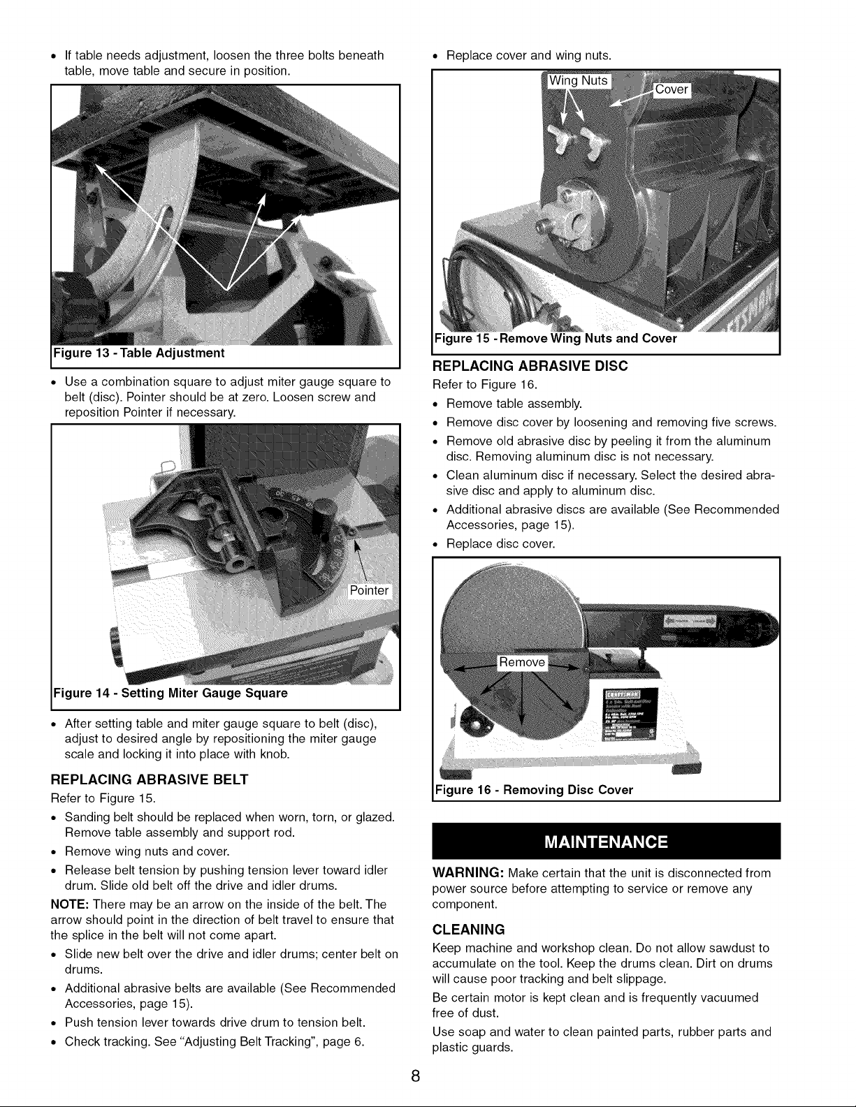
• If table needs adjustment, loosen the three bolts beneath
table, move table and secure in position.
Figure 13 -Table Adjustment
• Use a combination square to adjust miter gauge square to
belt (disc). Pointer should be at zero. Loosen screw and
reposition Pointer if necessary.
• Replace cover and wing nuts.
Figure 15 -Remove Wing Nuts and Cover
REPLACING ABRASIVE DISC
Refer to Figure 16.
• Remove table assembly.
• Remove disc cover by loosening and removing five screws.
• Remove old abrasive disc by peeling it from the aluminum
disc. Removing aluminum disc is not necessary.
• Clean aluminum disc if necessary. Select the desired abra-
sive disc and apply to aluminum disc.
• Additional abrasive discs are available (See Recommended
Accessories, page 15).
• Replace disc cover.
ii
Figure 14 - Setting Miter Gauge Square
• After setting table and miter gauge square to belt (disc),
adjust to desired angle by repositioning the miter gauge
scale and locking it into place with knob.
REPLACING ABRASIVE BELT
Refer to Figure 15.
• Sanding belt should be replaced when worn, torn, or glazed.
Remove table assembly and support rod.
• Remove wing nuts and cover.
• Release belt tension by pushing tension lever toward idler
drum. Slide old belt off the drive and idler drums.
NOTE: There may be an arrow on the inside of the belt. The
arrow should point in the direction of belt travel to ensure that
the splice in the belt will not come apart.
• Slide new belt over the drive and idler drums; center belt on
drums.
• Additional abrasive belts are available (See Recommended
Accessories, page 15).
• Push tension lever towards drive drum to tension belt.
• Check tracking. See "Adjusting Belt Tracking", page 6.
Figure 16 - Removing Disc Cover
WARNING: Make certain that the unit is disconnected from
power source before attempting to service or remove any
component.
CLEANING
Keep machine and workshop clean. Do not allow sawdust to
accumulate on the tool. Keep the drums clean. Dirt on drums
will cause poor tracking and belt slippage.
Be certain motor is kept clean and is frequently vacuumed
free of dust.
Use soap and water to clean painted parts, rubber parts and
plastic guards.
8

LUBRICATION
The shielded ball bearings in this tool are permanently
lubricated at the factory. They require no further lubrication.
• When operation seems stiff, a light coat of paste wax
applied to the belt table and disc table will make it easier to
feed the work while finishing.
• Do not apply wax to the belt platen. Belt could pick up wax
and deposit it on wheels causing belt to slip.
KEEP TOOL IN REPAIR
• If power cord is worn, cut, or damaged in any way, have it
replaced immediately.
• Replace worn abrasives when needed.
• Replace any damaged or missing parts. Use parts list to
order parts.
Any attempt to repair motor may create a hazard unless
repair is done by a qualified service technician. Repair
service is available at your nearest Sears store.
SYMPTOM
Motor willnotstart
Motor will not start;
fuses blown or circuit
breakers are tripped
Motor fails to develop full
power (power output of
motor decreases rapidly
with decrease in voltage
at motor terminals)
Motor overheats Motor overloaded
Motor stalls (resulting in
blown fuses or tripped
circuit breakers)
POSSIBLE CAUSE(S)
1. Low voltage
2. Open circuit in motor or loose
connections
3. Defective switch
4. Defective capacitor
1. Short circuit in line cord or plug
2. Short circuit in motor or loose
connections
3. Incorrect fuses or circuit breakers in
power line
1. Power line overloaded with lights,
appliances and other motors
2. Undersize wires or circuits too long
3. General overloading of power
company's facilities
1. Short circuit in motor or loose
connections
2. Low voltage
3. Incorrect fuses or circuit breakers in
power line
4. Motor overload
CORRECTIVE ACTION
1. Check power line for proper voltage
2. Inspect all lead connections on motor for loose or
open connection
3. Replace switch
4. Replace capacitor
1. Inspect line cord or plug for damaged insulation and
shorted wires
2. Inspect all lead connections on motor for loose or
shorted terminals or worn insulation on wires
3. Install correct fuses or circuit breakers
1. Reduce the load on the power line
2. Increase wire sizes, or reduce length of wiring
3. Request a voltage check from the power company
Reduce load on motor
1. Inspect connections in motor for loose or shorted
terminals or worn insulation on lead wires
2. Correct the low line voltage conditions
3. Install correct fuses or circuit breakers
4. Reduce load on motor
Machine slows down 1. Applying too much pressure to workpiece
while operating 2. Belt Slipping
Abrasive belt runs off top Not tracking properly
wheel
9
1. Ease up on pressure
2. Increase V-belt tension
See operation "Adjusting Belt Tracking"
 Loading...