

Page 1
UNPACKING
• Check for completeness.Locate all parts before attempting
assembly (see Figure 1).
NOTE: Hardwareto mount toolsto standis notincluded.
CAUTION: Do not attempt assembly if parts are
missing.Follow assembly instructions.Use parts list
to order replacement parts.
A Long Upper Cross Brace (2 each)
B Short Upper Cress Brace (2 each)
C Long Lower Cross Brace(2 each)
D Short Lower Cross Braco (2 each)
E Leg (4 each)
F Top (2 each)
Hardware Bag (not shown)
Figure 1 - Unpacldng
ASSEMBLY
Tools required: Phillipsscrewdriver, adjustable wrench and
portable drill.
ASSEMBLE FRAME
NOTE: Finger_ghten fastanemun_lall metal componentsare
assembled.Then tighten all fastoners securely.
NOTE: Use pan head screws and lock nuts.(Figure 7, Key
Nos. 8 and 9) to assemble all components except the top and
leveling pad.
• Assemblea long upper cress brace (A) and a long lower
cross brace (C) to the _ legs (E}.The braces areassem-
bled to the INSIDE of the legs (see Figure 2),
• Repeat for the othertwo legs and longcress braces.
A
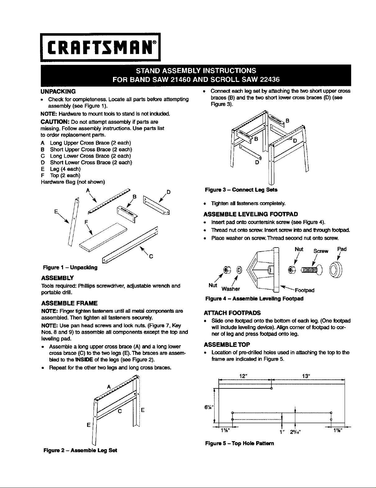
• Connecteach leg set by attachingthe two short uppercross
braces(B) and the twoshort lowercross braces(D) (see
Figure3).
D
Figure 3 - Connect Leg Sets
• Tighten all fastanemcompletely.
ASSEMBLE LEVEUNG FOOTPAD
• Insertpad onto countominkscrew (see Figure4).
• Thread nut onto screw.Insert screwintoand throughfootpad.
• Place washer on screw.Thread second nutonto screw.
Nut Screw Pad
Nut /
Washer _ _Footpad
Figure 4 - Assemble Leveling Footpad
ATTACH FOOTPADS
• Slide one footpadonto the bottomof each leg.(One footpad
willincludeleveling device).Align cornerof footpadto cor-
ner of leg and pressfootpad onto leg.
ASSEMBLE TOP
• Locationof pre-drilledholesused in attachingthe toptothe
frame are indicatedin Figure 5.
13"
E
Figure 2 - Assemble Leg Set
E
1%" 1" 25/_6" 1%"
Figure 5 -Top Hole Pattern
Page 2
• Placetheboardstogetherandthenplacethe assembled
frame onthe boards,Attach flame to boards usingwood
screws and washers throughthe slots in the frame (see
Rgum 6),
NOTE: The center screw requires one washer under the
screw head and one additional washer between the frame
and board.
Center Screw Requires
Extra Washer Between
Tabletop and Frame
\
IMPORTANT: Forscroll saw 22436, the two rear and one of
the frontmounting belts willneed to be located through the
slots in the frame. Carefully ddll the two holes shown in
Figure7 and then place saw on stand, mark Ioca_on of the
other two holes, then drill holes.
_ 2_/=" "/,e"
Figure 6 - Attaching the Top
Figure 7 - Drill Mounting Holes for Scroll Saw
3
4
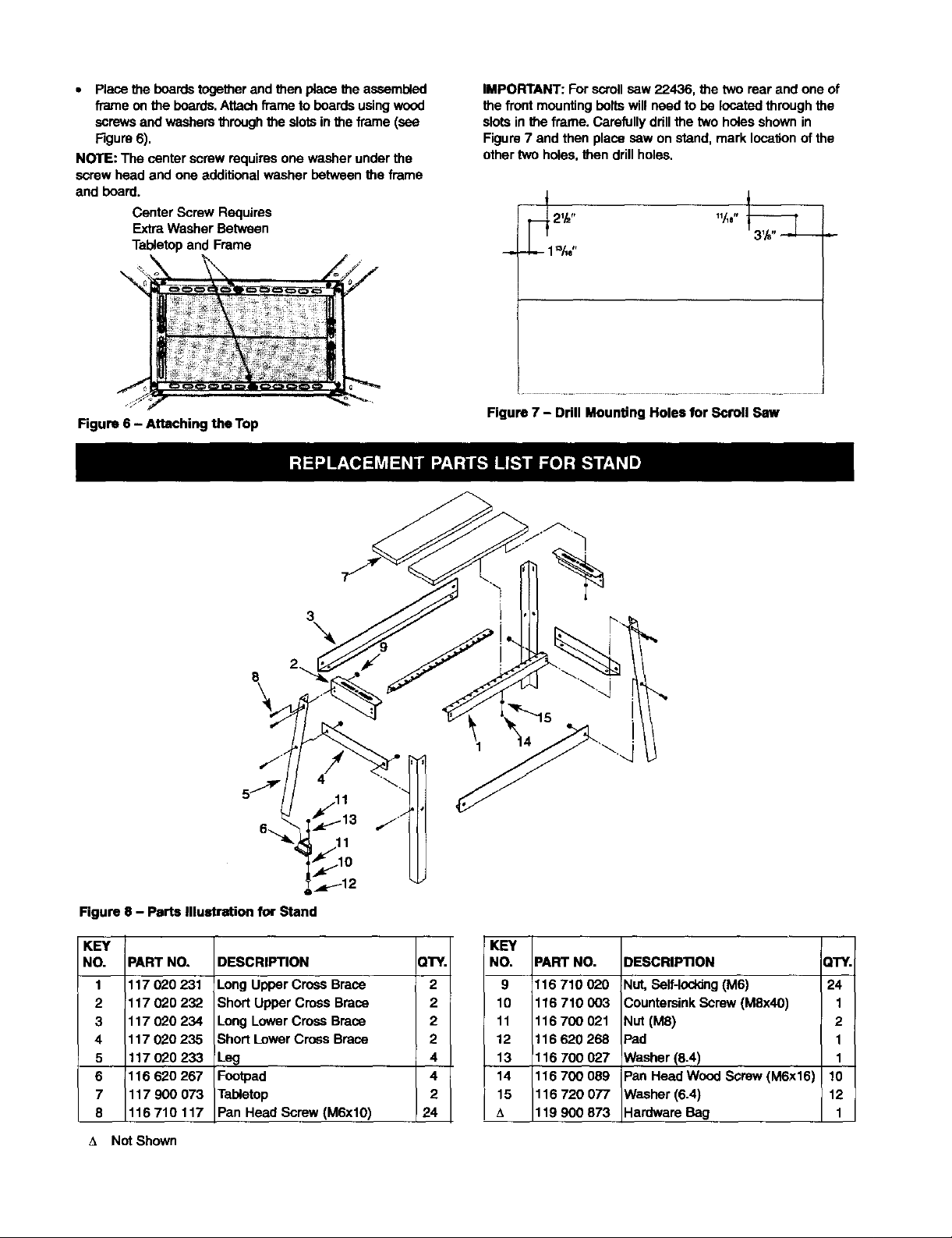
Figure 8 - Parts Illustration for Stand
KEY
NO. PART NO.
1 117020231
2 117020232
3 117020234
4 117020235
5 117020233
6 116 620 267
7 117900073
8 116710117
DESCRIPTION
Long Upper Crces Brace
Short Upper Cross Brace
Long Lower Cross Brace
Short LowerCross Brace
Leg
Footpad
Tabletop
Pan Head Screw (M6xl0)
A Not Shown
._p_-12
QTY.
2
2
2
2
4
4
2
24
KEY
NO.
9
10
11
12
13
14
15
A
PART NO.
116 710 020
116 710 003
116700021
116 620 268
116 700 027
116 700 089
116 720 077
119 900 873
DESCRIPTION QTY.
Nut,Self-loddng (M6) 24
CountersinkScrew (M8x40) 1
Nut (M8) 2
Pad 1
Washer
(8.4) I 1
I
Pan Head Wood Screw (M6x16) ! 10
Washer (6.4) 12
Hardware Bag 1
 Loading...