

Craftsman 351224010 Owner’s Manual

Operator's Manual
CRRFTSMRH
PR 0 FESS I 0 NAL i
BAND SAW
14"
Model No.
351.224010
CAUTION: Read and follow
all Safety Rules and Operating
Instructions before First Use
of this Product.
Sears, Roebuck and Co., Hoffman Estates, IL 60179 U.S.A.
www.sears.com/craftsman
29695.00 Draft (12/08)
Customer Helpline
1-800-266-9079
Please have your Model No.
and Serial No. available.
Warranty.................................... 2
SafetyRules............................... 2-3
Unpacking.................................. 3
Assembly................................. 3-6
Installation................................. 6-8
Operation................................ 8-12
Maintenance............................. 12-13
Troubleshooting............................. 14
PartsIllustrationsandLists.................. 15-19
EspaSol................................. 20-32
ONE-YEAR FULL WARRANTY ON
CRAFTSMAN TOOL
If this Craftsman tool fails due to a defect in material or
workmanship within one year from the date of purchase,
CALL 1-800-4-MY-HOME® TO ARRANGE FOR FREE
REPAIR (or replacement if repair proves impossible).
If this tool is used for commercial or rental purposes,
this warranty will apply for only ninety days from the
date of purchase.
This warranty applies only while this tool is in the
United States.
This warranty gives you specific legal rights, and you may
also have other rights, which vary, from state to state.
Sears, Roebuck and Co., Hoffman Estates, IL 60179
BE PREPARED FOR JOB
• Wear proper apparel. Do not wear loose clothing,
gloves, neckties, rings, bracelets or other jewelry
which may get caught in moving parts of machine.
• Wear protective hair covering to contain long hair.
• Wear safety shoes with non-slip soles.
• Wear safety glasses complying with United States
ANSI Z87.1. Everyday glasses have only impact
resistant lenses. They are NOT safety glasses.
• Wear face mask or dust mask if operation is dusty.
• Be alert and think clearly. Never operate power tools
when tired, intoxicated or when taking medications
that cause drowsiness.
PREPARE WORK AREA FOR JOB
• Keep work area clean. Cluttered work areas invite
accidents.
• Do not use power tools in dangerous environments.
Do not use power tools in damp or wet locations. Do
not expose power tools to rain.
• Work area should be properly lighted.
• Proper electrical receptacle should be available for
tool. Three-prong plug should be plugged directly
into properly grounded, three-prong receptacle.
• Extension cords should have a grounding prong and
the three wires of the extension cord should be of
the correct gauge.
• Keep visitors at a safe distance from work area.
• Keep children out of workplace. Make workshop
childproof. Use padlocks, master switches or remove
switch keys to prevent any unintentional use of
power tools.
PROPOSITION 65 WARNING: Some dust created
by power sanding, sawing, grinding, drilling and other
construction activities contains chemicals known to the
state of California to cause cancer, birth defects or
other reproductive harm.
Some examples of these chemicals are:
• Lead from lead-based paints.
• Crystalline silica from bricks and cement and other
masonry products.
• Arsenic and chromium from chemically-treated lumber.
Your risk from these exposures vary, depending on how
often you do this type of work. To reduce your exposure
to these chemicals: work in a well ventilated area and
work with approved safety equipment. Always wear
OSHNNIOSH approved, properly fitting face mask or
respirator when using such tools.
WARNING: For your own safety, read all of the
instructions and precautions before operating tool.
CAUTION: Always follow proper operating procedures
as defined in this manual -- even if you are familiar
with use of this or similar tools. Remember that being
careless for even a fraction of a second can result in
severe personal injury.
TOOL SHOULD BE MAINTAINED
° Always unplug tool prior to inspection.
• Consult manual for specific maintaining and adjust-
ing procedures.
• Keep tool lubricated and clean for safest operation.
• Remove adjusting tools. Form habit of checking to
see that adjusting tools are removed before switch-
ing machine on.
• Keep all parts in working order. Check to determine
that the guard or other parts will operate properly
and perform their intended function.
• Check for damaged parts. Check for alignment of
moving parts, binding, breakage, mounting and any
other condition that may affect a tool's operation.
• A guard or other part that is damaged should be
properly repaired or replaced. Do not perform
makeshift repairs. (Use parts list provided to order
replacement parts.)
KNOW HOW TO USE TOOL
. Use right tool for job. Do not force tool or attachment
to do a job for which it was not designed.
. Disconnect tool when changing blade.
. Avoid accidental start-up. Make sure that the tool is
in the "off" position before plugging in.
© Sears, Roebuck and Co, 2
• Do not force tool. It will work most efficiently at the
rate for which it was designed.
• Keep hands away from moving parts and cutting
surfaces.
• Never leave tool running unattended. Turn the power
off and do not leave tool until it comes to a complete
stop.
• Do not overreach. Keep proper footing and balance.
• Never stand on tool. Serious injury could occur if tool
is tipped or if blade is unintentionally contacted.
• Know your tool. Learn the tool's operation, applica-
tion and specific limitations.
• Use recommended accessories. Use of improper
accessories may cause risk of injury to persons.
• Handle workpiece correctly. Protect hands from pos-
sible injury.
• Turn machine off if it jams. Blade jams when it digs
too deeply into workpiece. (Motor force keeps it
stuck in the work.) Do not remove jammed or cut off
pieces until the saw is turned off, unplugged and the
blade has stopped.
• Maintain proper adjustment of blade tension, blade
guides and thrust bearings.
• Adjust upper guide to just clear workpiece.
• Hold workpiece firmly against table.
• DIRECTION OF FEED: Feed work into a blade or
cutter against the direction of rotation of the blade or
cutter only.
WARNING: The operation of any power tool can result
in foreign objects being thrown into the eyes, which can
result in severe eye damage. Always wear safety goggles
complying with United States ANSI Z87.1 (shown on
package) before commencing power tool operation.
Safety goggles are available through your Sears catalog.
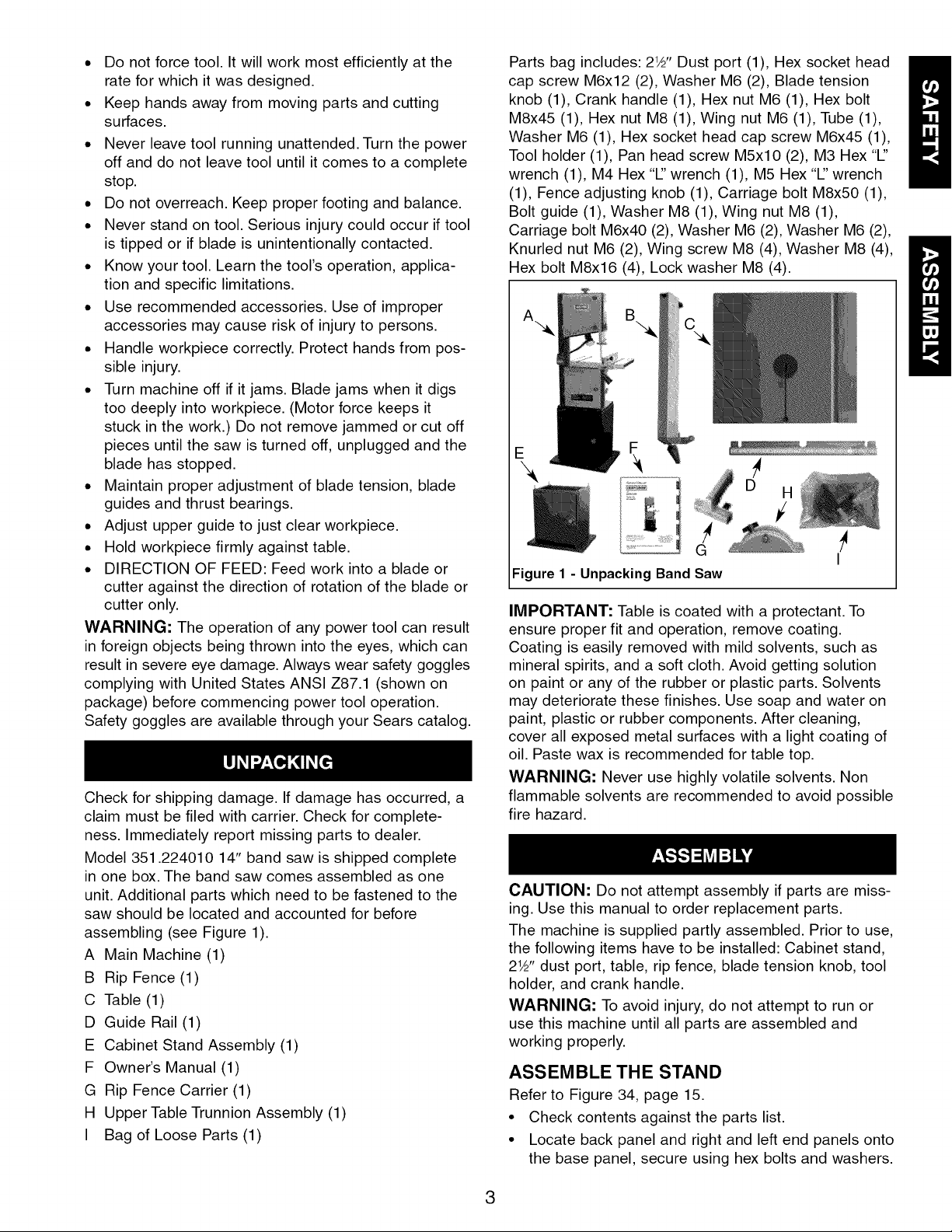
Check for shipping damage. If damage has occurred, a
claim must be filed with carrier. Check for complete-
ness. Immediately report missing parts to dealer.
Model 351.224010 14" band saw is shipped complete
in one box. The band saw comes assembled as one
unit. Additional parts which need to be fastened to the
saw should be located and accounted for before
assembling (see Figure 1).
A Main Machine (1)
B Rip Fence (1)
C Table (1)
D Guide Rail (1)
E Cabinet Stand Assembly (1)
F Owner's Manual (1)
G Rip Fence Carrier (1)
H Upper Table Trunnion Assembly (1)
I Bag of Loose Parts (1)
Parts bag includes: 21_'' Dust port (1), Hex socket head
cap screw M6x12 (2), Washer M6 (2), Blade tension
knob (1), Crank handle (1), Hex nut M6 (1), Hex bolt
M8x45 (1), Hex nut M8 (1), Wing nut M6 (1), Tube (1),
Washer M6 (1), Hex socket head cap screw M6x45 (1),
Tool holder (1), Pan head screw M5xl 0 (2), M3 Hex "1"
wrench (1), M4 Hex "1" wrench (1), M5 Hex "1" wrench
(1), Fence adjusting knob (1), Carriage bolt M8x50 (1),
Bolt guide (1), Washer M8 (1), Wing nut M8 (1),
Carriage bolt M6x40 (2), Washer M6 (2), Washer M6 (2),
Knurled nut M6 (2), Wing screw M8 (4), Washer M8 (4),
Hex bolt M8x16 (4), Lock washer M8 (4).
E
D H
I
Figure 1 - Unpacking Band Saw
IMPORTANT: Table is coated with a protectant. To
ensure proper fit and operation, remove coating.
Coating is easily removed with mild solvents, such as
mineral spirits, and a soft cloth. Avoid getting solution
on paint or any of the rubber or plastic parts. Solvents
may deteriorate these finishes. Use soap and water on
paint, plastic or rubber components. After cleaning,
cover all exposed metal surfaces with a light coating of
oil. Paste wax is recommended for table top.
WARNING: Never use highly volatile solvents. Non
flammable solvents are recommended to avoid possible
fire hazard.
CAUTION: Do not attempt assembly if parts are miss-
ing. Use this manual to order replacement parts.
The machine is supplied partly assembled. Prior to use,
the following items have to be installed: Cabinet stand,
21_'' dust port, table, rip fence, blade tension knob, tool
holder, and crank handle.
WARNING: To avoid injury, do not attempt to run or
use this machine until all parts are assembled and
working properly.
ASSEMBLE THE STAND
Refer to Figure 34, page 15.
• Check contents against the parts list.
• Locate back panel and right and left end panels onto
the base panel, secure using hex bolts and washers.
/
3
• Fasten the right and left end panels to the back
panel, secure using hex bolts and washers.
• Fasten the front bracing member on to the right and
left end panels assemble using hex bolts and wash-
ers. Fasten the shelf on the right and left end panels
using remaining hex bolts and washers.
• Fit the door on to the end panel.
• With assistance lift bandsaw and carefully position in
place on top of workstand.
• Fix in position using hex bolts, through washer, cabi-
net stand, washer, hex nut, bandsaw and lock wash-
er then secure on upper side with hex nut. Repeat
procedure for all four corners before tightening fully.
WARNING: To Avoid back injury, get help lifting the band
saw. Bend your knees, lift with your legs, not your back.
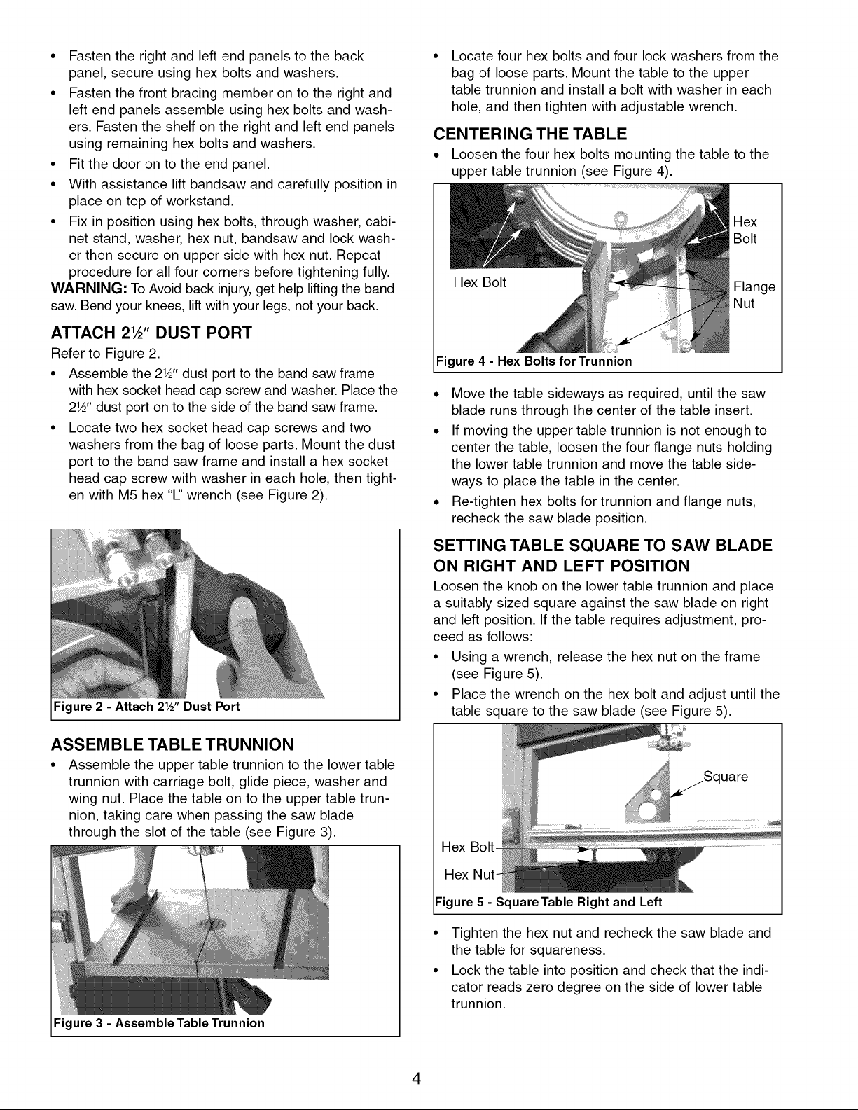
ATTACH 21/_'' DUST PORT
Refer to Figure 2.
• Assemble the 21_'' dust port to the band saw frame
with hex socket head cap screw and washer. Place the
21/_'' dust port on to the side of the band saw frame.
• Locate two hex socket head cap screws and two
washers from the bag of loose parts. Mount the dust
port to the band saw frame and install a hex socket
head cap screw with washer in each hole, then tight-
en with M5 hex "1"wrench (see Figure 2).
Locate four hex bolts and four lock washers from the
bag of loose parts. Mount the table to the upper
table trunnion and install a bolt with washer in each
hole, and then tighten with adjustable wrench.
CENTERING THE TABLE
• Loosen the four hex bolts mounting the table to the
upper table trunnion (see Figure 4).
Hex Bolt
Figure 4 - Hex Bolts for Trunnion
. Move the table sideways as required, until the saw
blade runs through the center of the table insert.
. If moving the upper table trunnion is not enough to
center the table, loosen the four flange nuts holding
the lower table trunnion and move the table side-
ways to place the table in the center.
. Re-tighten hex bolts for trunnion and flange nuts,
recheck the saw blade position.
Figure 2 - Attach 21,5', Dust Port
ASSEMBLE TABLE TRUNNION
• Assemble the upper table trunnion to the lower table
trunnion with carriage bolt, glide piece, washer and
wing nut. Place the table on to the upper table trun-
nion, taking care when passing the saw blade
through the slot of the table (see Figure 3).
Figure 3 - Assemble Table Trunnion
SETTING TABLE SQUARE TO SAW BLADE
ON RIGHT AND LEFT POSITION
Loosen the knob on the lower table trunnion and place
a suitably sized square against the saw blade on right
and left position. If the table requires adjustment, pro-
ceed as follows:
• Using a wrench, release the hex nut on the frame
(see Figure 5).
• Place the wrench on the hex bolt and adjust until the
table square to the saw blade (see Figure 5).
aex
Hex
Figure 5 - Square Table Right and Left
• Tighten the hex nut and recheck the saw blade and
the table for squareness.
• Lock the table into position and check that the indi-
cator reads zero degree on the side of lower table
trunnion.
4
• Loosen the screw securing the indicator and reset if
necessary to give zero degree reading (see Figure 6).
Figure 6 - Set Indicator to Zero
SETTING TABLE SQUARE FRONT AND
BACK OF BLADE
Place a suitably sized square against the saw blade on
back and forth position. If the table requires adjustment,
proceed as follows:
• Using a wrench, release the flange nut on the lower
table trunnion (see Figure 7).
• Place the M5 Hex "1" wrench on the hex socket set
screw and adjust until the table is square to the saw
blade on the front and back position (see Figure 7).
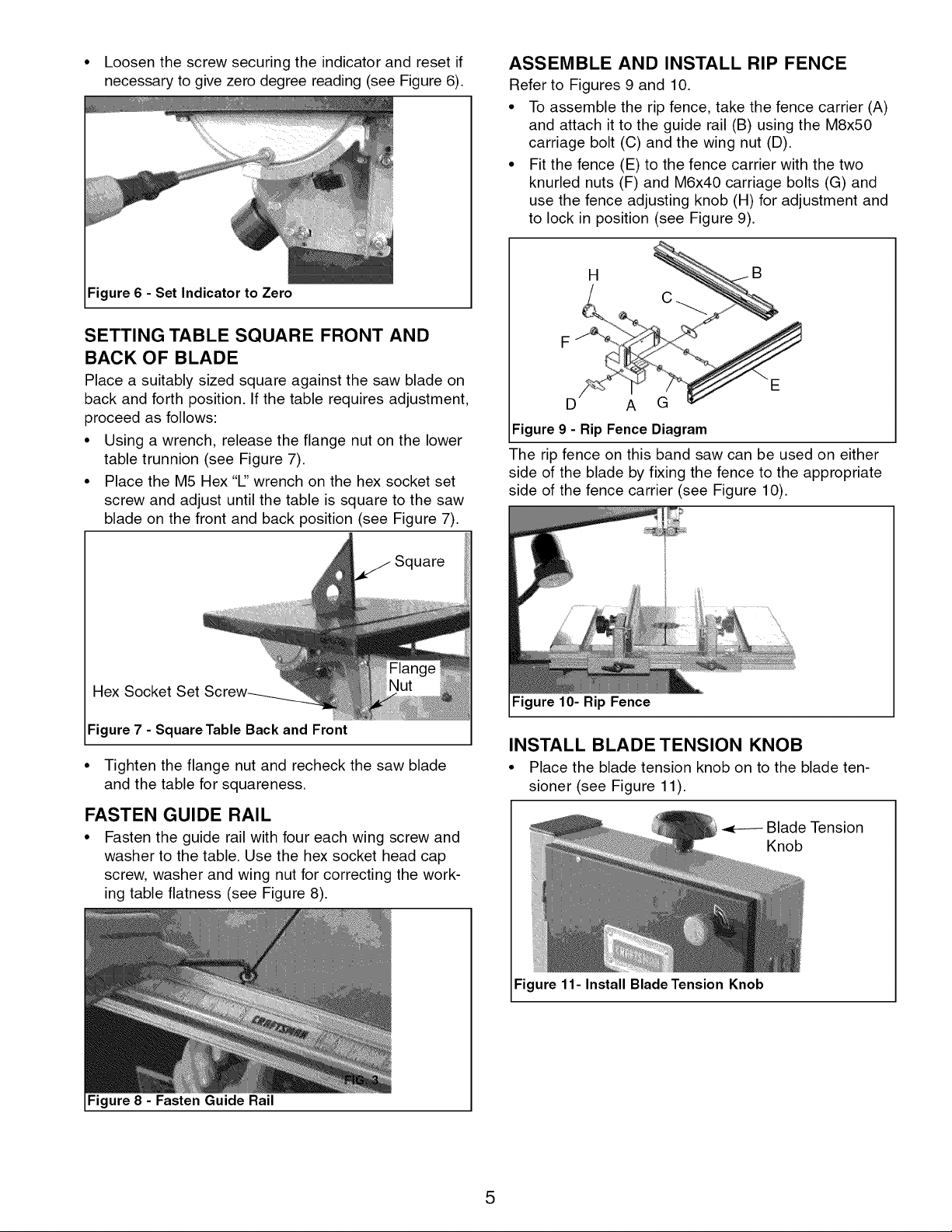
ASSEMBLE AND INSTALL RIP FENCE
Refer to Figures 9 and 10.
• To assemble the rip fence, take the fence carrier (A)
and attach it to the guide rail (B) using the M8x50
carriage bolt (C) and the wing nut (D).
• Fit the fence (E) to the fence carrier with the two
knurled nuts (F) and M6x40 carriage bolts (G) and
use the fence adjusting knob (H) for adjustment and
to lock in position (see Figure 9).
Figure 9 - Rip Fence Diagram
The rip fence on this band saw can be used on either
side of the blade by fixing the fence to the appropriate
side of the fence carrier (see Figure 10).
Square
Hex Socket Set
Figure 7 - Square Table Back and Front
• Tighten the flange nut and recheck the saw blade
and the table for squareness.
FASTEN GUIDE RAIL
• Fasten the guide rail with four each wing screw and
washer to the table. Use the hex socket head cap
screw, washer and wing nut for correcting the work-
ing table flatness (see Figure 8).
Figure 10- Rip Fence
INSTALL BLADE TENSION KNOB
• Place the blade tension knob on to the blade ten-
sioner (see Figure 11).
Blade Tension
Knob
Figure 11- Install Blade Tension Knob
Figure 8 - Fasten Guide Rail
5
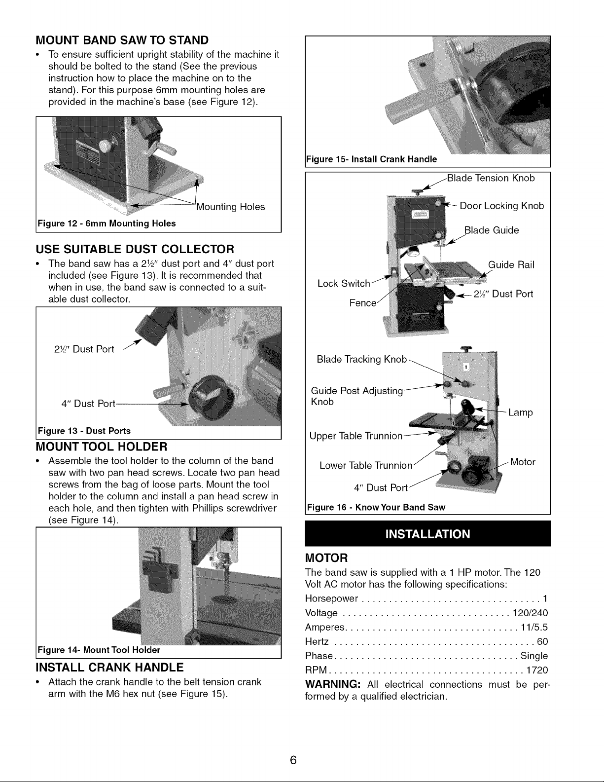
MOUNT BAND SAW TO STAND
• To ensure sufficient upright stability of the machine it
should be bolted to the stand (See the previous
instruction how to place the machine on to the
stand). For this purpose 6mm mounting holes are
provided in the machine's base (see Figure 12).
Figure 15-Install Crank Handle
Knob
#lounting Holes
Figure 12 - 6mm Mounting Holes
USE SUITABLE DUST COLLECTOR
• The band saw has a 2W' dust port and 4" dust port
included (see Figure 13). It is recommended that
when in use, the band saw is connected to a suit-
able dust collector.
2½" Dust Port
4" Dust Port
Figure 13 - Dust Ports
MOUNT TOOL HOLDER
• Assemble the tool holder to the column of the band
saw with two pan head screws. Locate two pan head
screws from the bag of loose parts. Mount the tool
holder to the column and install a pan head screw in
each hole, and then tighten with Phillips screwdriver
(see Figure 14).
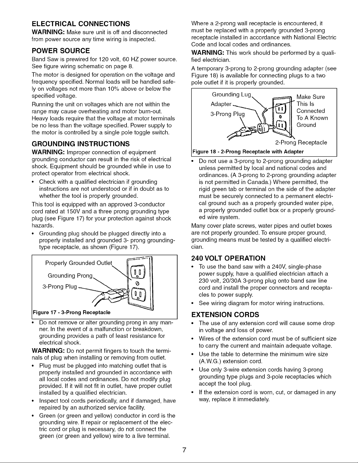
Door Locking Knob
Blade Guide
Guide Rail
Lock
2_" Dust Port
Blade Tracking
Guide Post Adjusting
Knob
Upper Table
Lower
4" Dust Port
Figure 16 - KnowYour Band Saw
Figure 14- MountTool Holder
INSTALL CRANK HANDLE
• Attach the crank handle to the belt tension crank
arm with the M6 hex nut (see Figure 15).
MOTOR
The band saw is supplied witha 1 HP motor. The 120
Volt AC motor has the following specifications:
Horsepower ................................. 1
Voltage ............................... 120/240
Amperes ................................ 11/5.5
Hertz ..................................... 60
Phase .................................. Single
RPM .................................... 1720
WARNING: All electrical connections must be per-
formed by a qualified electrician.
6
ELECTRICAL CONNECTIONS
WARNING: Make sure unit is off and disconnected
from power source any time wiring is inspected.
POWER SOURCE
Band Saw is prewired for 120 volt, 60 HZ power source.
See figure wiring schematic on page 8.
The motor is designed for operation on the voltage and
frequency specified. Normal loads will be handled safe-
ly on voltages not more than 10% above or below the
specified voltage.
Running the unit on voltages which are not within the
range may cause overheating and motor burn-out.
Heavy loads require that the voltage at motor terminals
be no less than the voltage specified. Power supply to
the motor is controlled by a single pole toggle switch.
GROUNDING INSTRUCTIONS
WARNING: Improper connection of equipment
grounding conductor can result in the risk of electrical
shock. Equipment should be grounded while in use to
protect operator from electrical shock.
• Check with a qualified electrician if grounding
instructions are not understood or if in doubt as to
whether the tool is properly grounded.
This tool is equipped with an approved 3-conductor
cord rated at 150V and a three prong grounding type
plug (see Figure 17) for your protection against shock
hazards.
• Grounding plug should be plugged directly into a
properly installed and grounded 3- prong grounding-
type receptacle, as shown (Figure 17).
Where a 2-prong wall receptacle is encountered, it
must be replaced with a properly grounded 3-prong
receptacle installed in accordance with National Electric
Code and local codes and ordinances.
WARNING: This work should be performed by a quali-
fied electrician.
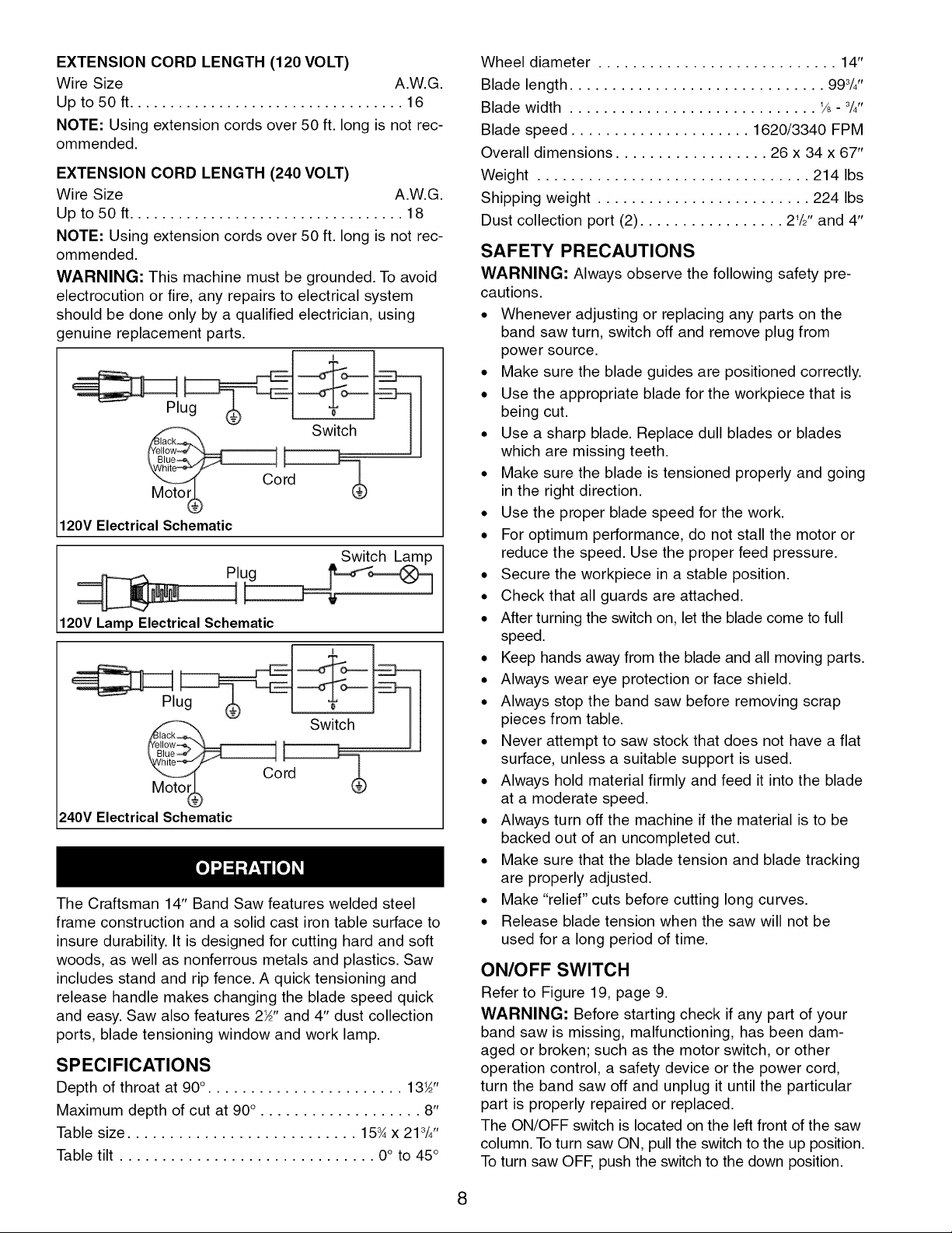
A temporary 3-prong to 2-prong grounding adapter (see
Figure 18) is available for connecting plugs to a two
3ole outlet if it is properly grounded.
Grounding Lug Make Sure
3-Prong Connected
Adapte_ This Is
2-Prong Receptacle
Figure 18 - 2-Prong Receptacle with Adapter
Do not use a 3-prong to 2-prong grounding adapter
unless permitted by local and national codes and
ordinances. (A 3-prong to 2-prong grounding adapter
is not permitted in Canada.) Where permitted, the
rigid green tab or terminal on the side of the adapter
must be securely connected to a permanent electri-
cal ground such as a properly grounded water pipe,
a properly grounded outlet box or a properly ground-
ed wire system.
Many cover plate screws, water pipes and outlet boxes
are not properly grounded. To ensure proper ground,
grounding means must be tested by a qualified electri-
cian.
To A Known
Ground
IF Properly Grounded Outlet . _:_
Grounding Prong II
3-Prong Plug II
igure 17 - 3-Prong Receptacle
• D--on-__o-ral---{__pr---_any man-
ner. In the event of a malfunction or breakdown,
grounding provides a path of least resistance for
electrical shock.
WARNING: Do not permit fingers to touch the termi-
nals of plug when installing or removing from outlet.
• Plug must be plugged into matching outlet that is
properly installed and grounded in accordance with
all local codes and ordinances. Do not modify plug
provided. If it will not fit in outlet, have proper outlet
installed by a qualified electrician.
• Inspect tool cords periodically, and if damaged, have
repaired by an authorized service facility.
• Green (or green and yellow) conductor in cord is the
grounding wire. If repair or replacement of the elec-
tric cord or plug is necessary, do not connect the
green (or green and yellow) wire to a live terminal.
240 VOLT OPERATION
• To use the band saw with a 240V, single-phase
power supply, have a qualified electrician attach a
230 volt, 20/30A 3-prong plug onto band saw line
cord and install the proper connectors and recepta-
cles to power supply.
• See wiring diagram for motor wiring instructions.
EXTENSION CORDS
• The use of any extension cord will cause some drop
in voltage and loss of power.
• Wires of the extension cord must be of sufficient size
to carry the current and maintain adequate voltage.
• Use the table to determine the minimum wire size
(A.W.G.) extension cord.
• Use only 3-wire extension cords having 3-prong
grounding type plugs and 3-pole receptacles which
accept the tool plug.
• If the extension cord is worn, cut, or damaged in any
way, replace it immediately.
7
EXTENSION CORD LENGTH (120 VOLT)
Wire Size A.W.G.
Up to 50 ft .................................. 16
NOTE: Using extension cords over 50 ft. long is not rec-
ommended.
EXTENSION CORD LENGTH (240 VOLT)
Wire Size A.W.G.
Up to 50 ft .................................. 18
NOTE: Using extension cords over 50 ft. long is not rec-
ommended.
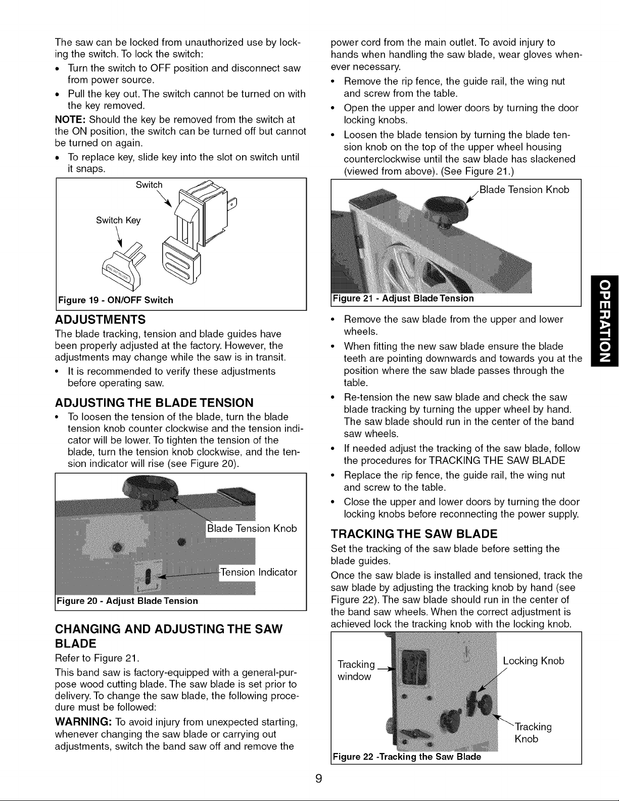
WARNING: This machine must be grounded. To avoid
electrocution or fire, any repairs to electrical system
should be done only by a qualified electrician, using
genuine replacement parts.
Moto_
120V Electrical Schematic
Switch Lamp
i
120V Lamp Electrical Schematic
__ Switch
Moto_ L_
240V Electrical Schematic
The Craftsman 14" Band Saw features welded steel
frame construction and a solid cast iron table surface to
insure durability. It is designed for cutting hard and soft
woods, as well as nonferrous metals and plastics. Saw
includes stand and rip fence. A quick tensioning and
release handle makes changing the blade speed quick
and easy. Saw also features 2_" and 4" dust collection
ports, blade tensioning window and work lamp.
SPECIFICATIONS
Depth of throat at 90°. ...................... 13_"
Maximum depth of cut at 90° . .................. 8"
Table size ........................... 15¾x 213/4''
Table tilt .............................. 0°to 45°
Wheel diameter ............................ 14"
Blade length .............................. 993/4''
Blade width ............................. 1/8- 3/4"
Blade speed ..................... 1620/3340 FPM
Overall dimensions .................. 26 x 34 x 67"
Weight ................................ 214 Ibs
Shipping weight ......................... 224 Ibs
Dust collection port (2) ................. 21/2'' and 4"
SAFETY PRECAUTIONS
WARNING: Always observe the following safety pre-
cautions.
* Whenever adjusting or replacing any parts on the
band saw turn, switch off and remove plug from
power source.
. Make sure the blade guides are positioned correctly.
• Use the appropriate blade for the workpiece that is
being cut.
• Use a sharp blade. Replace dull blades or blades
which are missing teeth.
• Make sure the blade is tensioned properly and going
in the right direction.
• Use the proper blade speed for the work.
• For optimum performance, do not stall the motor or
reduce the speed. Use the proper feed pressure.
• Secure the workpiece in a stable position.
• Check that all guards are attached.
• After turning the switch on, let the blade come to full
speed.
• Keep hands away from the blade and all moving parts.
• Always wear eye protection or face shield.
• Always stop the band saw before removing scrap
pieces from table.
• Never attempt to saw stock that does not have a flat
surface, unless a suitable support is used.
• Always hold material firmly and feed it into the blade
at a moderate speed.
• Always turn off the machine if the material is to be
backed out of an uncompleted cut.
• Make sure that the blade tension and blade tracking
are properly adjusted.
• Make "relief" cuts before cutting long curves.
• Release blade tension when the saw will not be
used for a long period of time.
ON/OFF SWITCH
Refer to Figure 19, page 9.
WARNING: Before starting check if any part of your
band saw is missing, malfunctioning, has been dam-
aged or broken; such as the motor switch, or other
operation control, a safety device or the power cord,
turn the band saw off and unplug it until the particular
part is properly repaired or replaced.
The ON/OFF switch is located on the left front of the saw
column. To turn saw ON, pull the switch to the up position.
Toturn saw OFF, push the switch to the down position.
8
The saw can be locked from unauthorized use by lock-
ing the switch. To lock the switch:
. Turn the switch to OFF position and disconnect saw
from power source.
. Pull the key out. The switch cannot be turned on with
the key removed.
NOTE: Should the key be removed from the switch at
the ON position, the switch can be turned off but cannot
be turned on again.
. To replace key, slide key into the slot on switch until
it snaps.
Switch
\
Switch Key
power cord from the main outlet. To avoid injury to
hands when handling the saw blade, wear gloves when-
ever necessary.
• Remove the rip fence, the guide rail, the wing nut
and screw from the table.
• Open the upper and lower doors by turning the door
locking knobs.
• Loosen the blade tension by turning the blade ten-
sion knob on the top of the upper wheel housing
counterclockwise until the saw blade has slackened
(viewed from above). (See Figure 21 .)
Tension Knob
Figure 19 - ON/OFF Switch
ADJUSTMENTS
The blade tracking, tension and blade guides have
been properly adjusted at the factory. However, the
adjustments may change while the saw is in transit.
• It is recommended to verify these adjustments
before operating saw.
ADJUSTING THE BLADE TENSION
• To loosen the tension of the blade, turn the blade
tension knob counter clockwise and the tension indi-
cator will be lower. To tighten the tension of the
blade, turn the tension knob clockwise, and the ten-
sion indicator will rise (see Figure 20).
Blade Tension Knob
Indicator
Figure 20 - Adjust Blade Tension
CHANGING AND ADJUSTING THE SAW
BLADE
Refer to Figure 21.
This band saw is factory-equipped with a general-pur-
pose wood cutting blade. The saw blade is set prior to
delivery. To change the saw blade, the following proce-
dure must be followed:
WARNING: To avoid injury from unexpected starting,
whenever changing the saw blade or carrying out
adjustments, switch the band saw off and remove the
Figure 21 - Adjust Blade Tension
• Remove the saw blade from the upper and lower
wheels.
• When fitting the new saw blade ensure the blade
teeth are pointing downwards and towards you at the
position where the saw blade passes through the
table.
• Re-tension the new saw blade and check the saw
blade tracking by turning the upper wheel by hand.
The saw blade should run in the center of the band
saw wheels.
• If needed adjust the tracking of the saw blade, follow
the procedures for TRACKING THE SAW BLADE
• Replace the rip fence, the guide rail, the wing nut
and screw to the table.
• Close the upper and lower doors by turning the door
locking knobs before reconnecting the power supply.
TRACKING THE SAW BLADE
Set the tracking of the saw blade before setting the
blade guides.
Once the saw blade is installed and tensioned, track the
saw blade by adjusting the tracking knob by hand (see
Figure 22). The saw blade should run in the center of
the band saw wheels. When the correct adjustment is
achieved lock the tracking knob with the locking knob.
Tracking
window
Figure 22 -Tracking the Saw Blade
Locking Knob
_Tracking
Knob
9
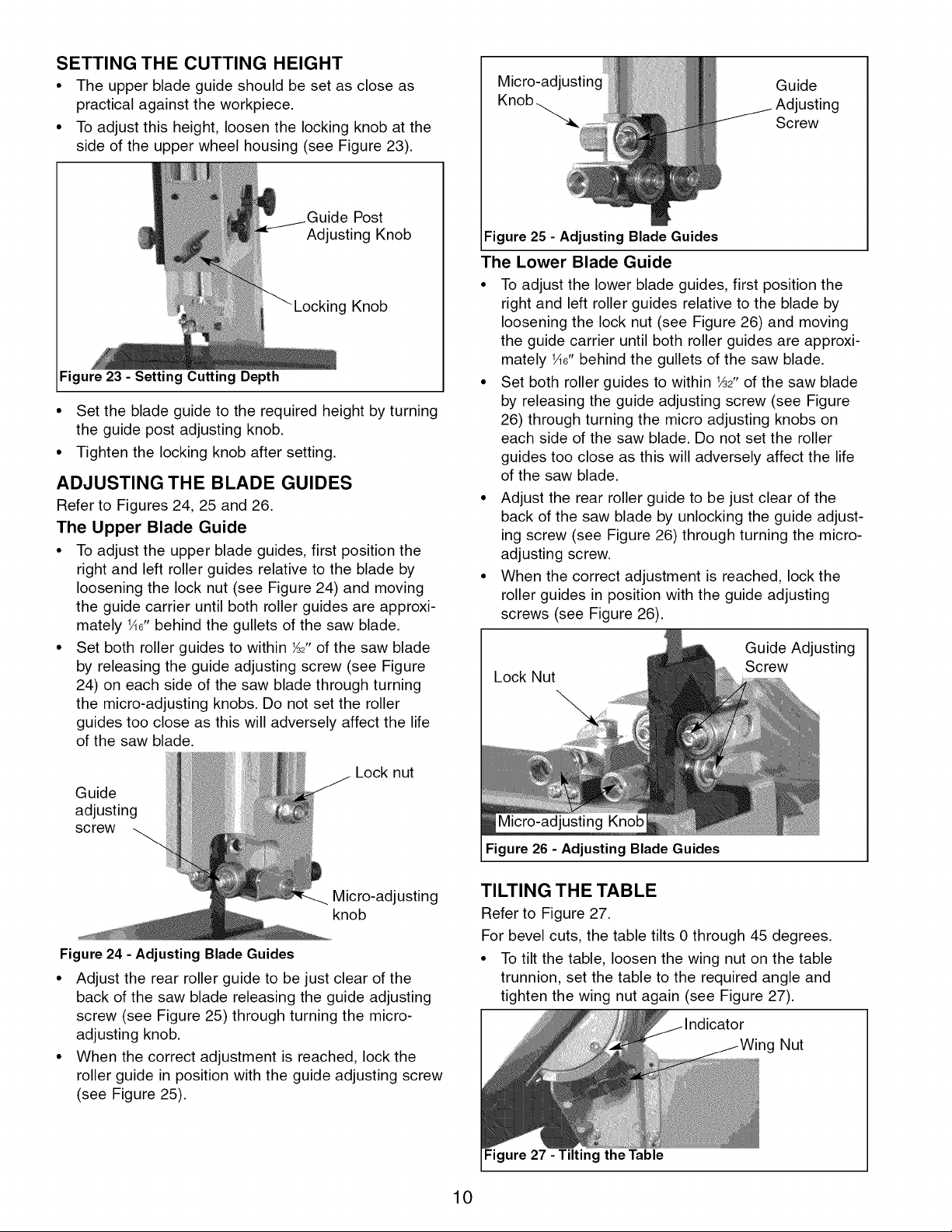
SETTING THE CUTTING HEIGHT
• The upper blade guide should be set as close as
practical against the workpiece.
• To adjust this height, loosen the locking knob at the
side of the upper wheel housing (see Figure 23).
Post
Adjusting Knob
g Knob
Figure 23 - Setting Cutting Depth
• Set the blade guide to the required height by turning
the guide post adjusting knob.
• Tighten the locking knob after setting.
ADJUSTING THE BLADE GUIDES
Refer to Figures 24, 25 and 26.
The Upper Blade Guide
• To adjust the upper blade guides, first position the
right and left roller guides relative to the blade by
loosening the lock nut (see Figure 24) and moving
the guide carrier until both roller guides are approxi-
mately lAG"behind the gullets of the saw blade.
• Set both roller guides to within _2" of the saw blade
by releasing the guide adjusting screw (see Figure
24) on each side of the saw blade through turning
the micro-adjusting knobs. Do not set the roller
guides too close as this will adversely affect the life
of the saw blade.
Micro-adjusting Guide
Knob_
Figure 25 - Adjusting Blade Guides
The Lower Blade Guide
• To adjust the lower blade guides, first position the
right and left roller guides relative to the blade by
loosening the lock nut (see Figure 26) and moving
the guide carrier until both roller guides are approxi-
mately He" behind the gullets of the saw blade.
• Set both roller guides to within _2" of the saw blade
by releasing the guide adjusting screw (see Figure
26) through turning the micro adjusting knobs on
each side of the saw blade. Do not set the roller
guides too close as this will adversely affect the life
of the saw blade.
• Adjust the rear roller guide to be just clear of the
back of the saw blade by unlocking the guide adjust-
ing screw (see Figure 26) through turning the micro-
adjusting screw.
• When the correct adjustment is reached, lock the
roller guides in position with the guide adjusting
screws (see Figure 26).
Lock Nut
Screw
Guide Adjusting
Screw
\
Lock nut
Guide
adjusting
screw
Micro-adjusting
knob
Figure 24 - Adjusting BladeGuides
• Adjust the rear roller guide to be just clear of the
back of the saw blade releasing the guide adjusting
screw (see Figure 25) through turning the micro-
adjusting knob.
• When the correct adjustment is reached, lock the
roller guide in position with the guide adjusting screw
(see Figure 25).
Micro-adjusting Knob
Figure 26 - Adjusting Blade Guides
TILTING THE TABLE
Refer to Figure 27.
For bevel cuts, the table tilts 0 through 45 degrees.
• To tilt the table, loosen the wing nut on the table
trunnion, set the table to the required angle and
tighten the wing nut again (see Figure 27).
Nut
Figure 27 - Tilting the Table
10
 Loading...