

Craftsman 35122312, 351221060 Owner’s Manual

Operator's Manual I
12"
MINI LATHE
Model No.
351.221060
CAUTION:
Read and follow all Safety
Rules and Operating
Instructions before First
Use of this Product. Keep
this Manual with Tool.
Sears, Roebuck and Co., Hoffman Estates, IL 60179 U.S.A.
V_N. sear S. CO rn]cra_t s ma n
23139,00 Draft (01/03/05)

Warranty ......................................... 2
Safety Rules .................................... 2-3
Unpacking ....................................... 3
Assambl_; ........................................ 3
Installation ...................................... 4-5
Operation ..................................... 5-13
Maintenance .................................... 14
Troubleshooti ng .................................. 15
Parts Illustration and List ........................ 16-17
FULL ONE YEAR WARRANTY
If this product fails due to a defect in material or workmanship
within one year from the date of purchase, Sears will at its
option repair or replace it free of charge. Contact your nearest
Sears Service Center (1-800-4-MY-HOME) to arrange for
product repair, or return this product to place of purchase for
replacement.
If this product is used for commercial or rental purposes, this .
warranty will appty for 90 days from the date of purchase.
This warranty applies only while this product is used in the
United States.
This warranty gives you specific legal rights and you may also
have other fights which vary from state to state.
Sears, Roebuck and Co., Dept. 817WA, Her[man Estates,
IL 60179
WARNING: For your own safety, read all of the instructions
and precautions before operating tool.
CAUTION: Always follow proper operating procedures as
defined in this manual -- even if you are familiar with usa of
this or similar tools. Remember that being careless for even a
fraction of a second can result in severe personal injury.
BE PREPARED FOR JOB
Wear proper apparel. Do not wear loose clothing, gloves,
nab<ties, rings, brecelets or other jewelry which may get
caught in moving parts of machine,
Wear protective hair covedng to contain fang hair.
Wear safety shoes with non-slip soles.
Wear safety glasses complying with United States ANSI
Z87.1. Everyday glasses have only impact resistant lenses.
They are NOT safety glasses.
Wear face mask or dust mask if operation is dusty,
Be alert and think dearly Never operate power fools when
tired, intoxicated or when taking medications that cause
drowsiness.
PREPARE WORK AREA FOR JOB
Keep work area clean. Cluttered work areaa invite accidents.
Do not use power tools in dangerous environments. Do not
use power tocts in damp or wet locations. Do not expose
power tools to rain,
© Seam, Roebuckand Co.
• Work area should be properly lighted.
• Keep visitors at a safe distance from work area,
- Keep chtidren out of workplace. Make workshop childproof.
Use padlocks, master switches or remove switch keys to
prevent any unintentional use of power tools.
• Keep power cords from coming in contact with sharp
objects, oil, grease, and hot surfaces.
TOOL SHOULD BE MAINTAINED
• Always unplug tool prior to inspection.
• Consult manual for specific maintaining and adjusting prc-
caduFeS,
Keep tool lubricated and clean for safest operation.
Keep all parts in working order. Check to determine that
the guard or other parts will operate property and perform
their intended function.
• Check for damaged parts. Check for alignment of moving
parts, binding, breakage, mounting and any other condition
that may affect a toots operation.
• A guard or other part that is damaged should be properly
repaired or replaced. Do not perform makeshift repairs.
(Use parts list provided to order replacement parts.)
• Never adjust attachments while running. Disconnect power
to avoid accidental start-up.
Have damaged or worn power cords replaced immediately
• Keep cutting tools sharp for effidant and safest operation.
KNOW HOW TO USE TOOL
Use right tool for job. Do not force tool or attachment to do
ajob for which it was not designed.
Disconnect tool when changing attachments.
• Avoid ar_.cidentalstart-up. Make sure that the tool is in the
=oil_ position before plugging in, turning on safety discon-
nect orac_vatingbreakers.
Do not force fool. It will work most eff]cientty at the rate for
which it was designed.
Keep hands away fromchuck,centersand othermovingparts
NeverleavetoctrunningunattendedTurnthepower off
and do not leave tool untilit comes to a complete stop.
Do not overreach. Keep proper footing and balance.
Never stand on tool. Serious injury could occur if tool is
tipped or ff centers are unintentionally contacted.
Know your tool. Learn the tool's operation,application and
specific limitations.
Handle workplace correctly. Mount firmly in holding
devices. Protect hands from possible injury.
• Turn machine off if workplace splits or besomes loose.
Use cuing tools as recommended in =Operation.=
WARNING: For your own safety, do not operate your wood
lathe unUlit is completaly assembled and installed accordingto
instruc'dons.
PROTECTION: EYES, HANDS, FACE, BODY, EARS
If any part of your lathe is missing, malfunctioning, or has
been damaged or broken, cease operating immedlataly
until the particular part is properly repaired or replaced.
• Wear safety goggles that cornpfywi_ United States ANSI
Z87.1 and aface shield or dust mask if operation is dusty
Wear ear plugs or muffs during extended periods of operation.
Small loose pieces of wood or other objects that contact a
spinning workplace can be propelled at very high speed.
This can be avoided by keeping the lathe clean.
2

N_ver turn the lathe ON before clearing the bed, head and
taifaiock of alltools, wood scraps, etc., except the workplece
and related support devices for the operation planned.
Never place your face or body in line with the chuck or
faceplate.
Never place your f_ngers or hands in path of cutting tools,
Never reach in beck of the work.piece with either hand to
support the piece, remove wood scraps, or for any other
reason. Avoid awkward operations and hand positions
where a sudden slip could cause fingers or hand to move
into a spinning workpiece.
Shut the lathe OFF and disconnect power source when
removing the faceplate, changing the center, adding or
removing an auxiliary device, or making adjustments.
Turn key lock switch to °off" and remove key when too! is
not in use.
If the workplace sp£ts or is damaged in any way, turn lathe
OFF and remove the workplace from the holders. Discard
damaged workplace and start with a new piece of wood.
Use extra care when turning wood with twisted grain or
wood that is twisted or bowed -- it may cut unevenly or
wobble excessively.
KNOW YOUR CUTTING TOOLS
Dull, gummy, improperly sharpened or set cutting tools can
cause vibration and chatter during cutting operations.
Minimize potential injury by proper care of tools and regu-
tar machine maintenance.
Never perform any operation with this lathe where thework-
piece is hand-held. Do not mount a reamer, milling cutter, drill
bit,wire wheel or buffing wheel to the headstock spindle.
When hand-sanding faceplate or between-centers mount-
ed workpieces, complete all sanding BEFORE removing
the workplace from the lathe.
Never nJn the spindle in the wrong direction, The cutting
tool couid be pulled from your hands. The workplace
should always turn towards the operator.
For spindle turning, ALWAYS poaitior) Me tool rest above the
cente_ne of the werkpiece and spindle (approximately '/R").
WARNING: Some dust created by power sanding, sawing,
grinding, drilling and other construction activities contains
chemicals known to cause cancer, birth defects or other
reproductive harm.
Some examples of these chemicals are:
• Lead from lead-based paints.
• Crystalline silica from bricks and cement and other
masonry products,
• Arsenic and chromium from chemically-treated lumber.
Your risk from these exposures vary, depending on how often
you do this type of work. To reduce your exposure to these
chemicals: work in a well ventilated area and work with
approved aafety equipment. Always wear MSHA/NIOSH
approved, properly fitting face mask or respirator when using
such tools.
M
U
THINK SAFETY
Safety is a combination of operator common sense and alert-
ness at all times when the lathe is being uaed.
For your own safety, read all rules and precautions in the
operator's manual before using this tool
For eye protection, wear safety glasses complying with
United States ANSI ZB7.1.
Do not wear loose clothing, gloves, neckties, rings,
bracelets or other jewelry that could get caught in moving
parts of machine or workpiece. Wear protective hair cover-
ing to contain long hair.
Tighten all clamps, tixturee end tailstock before applying
power. Check to make sure that all tools and wrenches
have been removed.
With switch off, rotate workplace by hand to make sure
that there is adequate clearance. Start the machine on
lowest speed setting to verify that the workplace is secure.
For large pieces, create a rough shape on another piece of
equipment before installing on faceplate.
Do not mount any workpieces that have splits or knots.
Never attempt to remount a faceplate turning to the face-
plate for any reason.
Never attempt to remount a between-centers turning ff the
original centers on the turning have been altered or removed.
• When remounting a between-centers turning that has non-
altered original centers, make sure that the speed is at the
lowest setting for start-up.
Use extra caution when mounting a between-centers turning
to the faceplate, or a faceplate turning to between-centers,
for aecondary operations. Make sure that the speed is at
the lowest setting for start-up.
Check for shipping damage. If damage has occurred, a claim
must be filed with CaTTier,Check for completeness. Immediately
repo,-[ missing parts to dealer.
Ycur wood lathe is shipped complete in one carton. Additional
parts which need to be assembled to lathe, should be located
and accounted for before assembly. Refer to Figure 42.
Mounting Plate (2), Key No. 26
M6 Square Nut (4), Key No. 27
M6 Flat Washer (4), Key No. 9
M6 x 12 Socket Head Bolt (4), Key No. 25
Support Rod (1), Key No. 46
Guard Assembly (1), Key Nos. 8, 48 and 49
Pen Mandrel System (1), Key No. 50
ff any parts are mieeing, do not attempt to assemble the Lathe,
plug in the power cord, or turn the _witch on until the missing
parts are obtained and properly installed.
Refer to Figure 42.
Slide a square nut (Key No. 27) into the front and rear
channels of the lathe bed (Key No. 28).
Place two M6 x 12 socket head bolts and fiat washers (Key
Nos. 9 and 25) into a mounting plate (Key No. 26).
• Thread bolts into the square nuts secureIF
Repeat for other mounting plate.
Insert guard support (Key No. 45) into tool rest base (Key
No.39). Secure in position with set screw (Key No. 36).
• Attach guard assembly to support Secure in posi_on with
wing nut (Key No. 49). Position guard over work.
3
LOCATION OF WOOD LATHE
The lathe should be positioned so that neither the operator
nor a casual observer is forced to stand in line with the spin-
ning chuck or workpiece.
WARNING: The lathe must be damped mrbolted securely to
work bench. An unbalanced workplace will cause the lathe to
shake and tip over.
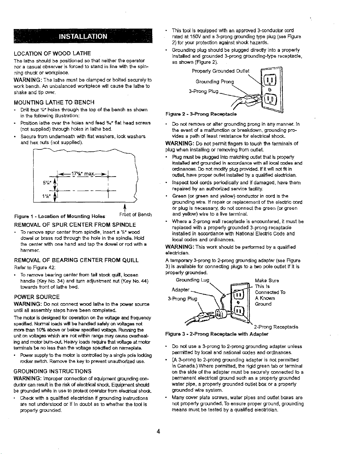
MOUNTING LATHE TO BENCH
• Dr!l[ four %" holes through the top of the bench as shown
in the following illustration:
• Position lathe over the holes and feed 31_,,"f_at head screws
(not supplied) through holes in lathe bed.
• Secure from underneath with fiat washera, lock washers
and hex nuts (not supplied).
_....,e-- 173/="maXl---a,.-___
5V[I l'l I
Figure 1 - Location of Mounting Holes
Rtnt Of
Bench
REMOVAL OF SPUR CENTER FROM SPINDLE
• Toremove spur center from spindle, insert a Y4"wood
dowel or brass rod through the hole in the spindle. Hold
the center with one hand and tap the dowel or rod with a
hammen
REMOVAL OF BEARING CENTER FROM QUILL
Refer to Figure 42:
• Toremove bearing center from tai! stoc_kqunl, loosen
handle (Key No. 34) and turn adjustment nut (Key No. 44)
t_vcardsfront of lathe bed.
POWER SOURCE
WARNING: Do notconnectwood lathe to the power source
until all assernb!y steps have been completed.
The motor is designed for opera,on onthe voltage and frequency
specil_ed.Normalloads will be handled safely onvoifages not
more than 10% above or below specked voltage.Running the
unitonvoltageswhich are not withinrange may cause overheat-
ingandmotor burn-out. Heavy loads require that voltage at motor
terminals be no less than the voltage specified on nameplate.
• F_:_versupply to the motor iscon_'olledby a single pole locking
roci<erswitch.Removethe key to prevent unauthorizeduse.
GROUNDING INSTRUCTIONS
WARNING: Improper connection of equipmentgroundingcon-
ductor can result in the dsk of elec_icel shock.Equipment should
be groundedwhile in use to protect operator from elec#'icefshock.
Check with a qualified electrician if grounding instruclJons
are not understood or if in doubt as to whether the tool is
properly grounded.
• This tool is equipped with an approved3-conductor cord
rated at 150V and a 3-prong grounding type plug (see F]gure
2) for your protection against shock hazards.
• Grounding plug should be plugged directly into a properly
installed and grounded 3-prong grounding-type receptacle,
as shown (Figure 2).
Propedy Grounded Outlet _-'------_'_
Grouodingprong 4@11
3-Prong Plug
Figure 2 - 3-Prong Receptacle
• Do not remove or alter grounding prong in any manner. In
the event of a malfunction or breakdown, grounding pro-
vides a path of least reeistance for elec'o-ical shock.
WARNING: Do net permit fingers to touch the terminals of
plug when installing or removing from outlet.
Plug must be plugged into matching outtatthat is properly
installedand groundedin accordancewith nillocal codes and
ordinances. Do notmodify plug provided. Ifit will not fit in
ou_et, have proper outtat installed by a qualiSedelectrician.
Inspect tool coeds periodically and if damaged, have them
repaired by an authorized service fectldy.
Green (or green and yellow) conductor in cord is the
grounding wire. If repair or replacement of the electric cord
or plug is necessary, de not connect the green (or green
and yellow) wire to a live terminal
- Where a 2-prong wall receptacle is encountered, it must be
replaced with a properly grounded 3-prong receptacle
installed in accordance with National Etacfric Code and
local codes and ordinances.
WARNING: This work should be performed by a qualified
etact]ictan.
A temporary 3-prong to 2-prong grounding adapter (see Figure
3) is available for connecting plugs to a two pete outlet ff it is
properly grounded.
Grounding Lug Make Sure
Adapter Donnected To
Ground
2-Prong Receptacle
Figure 3 - 2-Prong Receptacle with Adapter
- Do not use a 3-prong to 2-prong grounding adapter unless
permitted by local end national codes and ordinances.
• (A 3-prong to 2-prong grounding adapter is not permitted
in Canada.) Where permitted, the rigid green tab or terminal
on the side of the adapter must be securely connected to a
permanent electrical ground such as a properly grounded
water pipe, a properly grounded outlet box or a properly
grounded wire system.
• Many cover plate screws, water pipes and outlet boxes are
not properly grounded. To ensure proper ground, grounding
means must be tested by a qualified electrician.
4

EXTENSION CORDS
The use of any extension cord will cause some drop in
voltage and loss of power.
• Wires of the extension cord must be of sufficientsize to
carry the current and maintain adequate voltage.
• Use the table to determine the minimum wire size (A.W.G.)
extension cord.
• Use only 3-wire extension cords having 3-prong grounding
type plugs and3-pole receptacles which accept the too_plug.
• If the extension cord is worn, cut, or damaged in any way,
replace it immediately.
Extension Cord Length
Wire Size A.W.G.
Up to 25 ft........................................ 18
NOTE: Using extension cords over 25 ft. long is not
recommended.
MOTOR
The wood lathe is assembled with motor and wiring installed
as an integral part of the tool. The electrical wiring schematic
is shown in Figure 4 below.
Black "
1/O:rl Whita _=-S_
_j_Green
GRD
Figure 4 -Wiring Schematic
The 120 Vo!t AC motor has the following specifications:
Horsepower (Maximum Developed) ................... 't_
Voltage ........................................ 120
Amperes ....................................... 1.2
Hertz .......................................... 60
Phase ....................................... Single
RPM ......................................... 3450
Rotation (viewed from left side) ................ Clockwise
ELECTRICAL CONNECTIONS
WARNING: Make sure unit is off and disconnected from
power source before inspecting any wiring.
The motor is installed and wiring connected as illustrated in
the wiring schematic (see Figure 4).
The motor is assembled with an approved three conductor cord
to be used on 120 volts as indicated. The power supp)y to the
motor is controlled by a slngle pole rocker switch.
The power lines are inserted directly onto the switch. The
green ground line must remain securely fastened to the frame
to properly protect against electrical shock.
Refer to Figures 5 - 42.
DESCRIPTION
Craftsman 12" 3-speed wood lathe provides capability to turn
wooden workpieces up to 12" long and 4" diameter. The motor
rotates at 3450 RPM and the spindle speeds range from 1350
to 3500 RPM.
Lathe includes 2'/="face plate, spur and bearing centers, safety
guard and pen mandrel system.
SPECIFICATIONS
Turning length (max.) ............................. 12"
Swing over bed ................................... 4"
Swing over toolrest base .......................... 2't7"
Length ....................................... 235t_,"'
Width ......................................... 5%"
Height......................................... 8';t,"
Spindle speed ...................... 1350 to 3500 RPM
Spindle thread ................................ _1,"-'16
Spindle taper ................................. #1MT
Tailstock taper ................................. #1 MT
Tailstock quill travel .............................. 1'/_"
Switch .................................... 120V, SP
Motor .......................... 3450 RPM, 1.2 AMPS
Weight ...................................... 14 ]bs
WARNING: Operation of any power tool can result in foreign
objects being thrown into the eyes, which can result in severe
eye damage. Always wear safety goggles complying with
Unites States ANSi Z87.1 (shown on package) before com-
mencing power tool operation. Safety goggles are available at
Sears retail stores or catalog.
CAUTION: Always observe the following safety precautions:
SAFETY PRECAUTIONS
• Whenever adjusting or replacing any parts on the tool, turn
switch OFF and remove the plug from power source.
Recheck allIod{ing handles.They must be tightened securely
• Make sure all guards are properly attached. All guards
should be securely _stened.
- Make sure all moving parts are free and clear of any
interference.
• Make sure allfasteners are tight and have not vibrated loose.
• With power disconnected, test operation by hand for clear-
ance and adjust if necessary.
• Always wear eye protection or face shield.
• After turning switch on, always allow the spindle to come
up to full speed before turning.
• Be sure motor runs clockwise when viewing spindle exten-
sion from the left end (outboard side of headstock).
• Keep hands clear of spindle, centers, pulleys and other
moving parts of machine.
• For optimum performance, do not stall motor or reduce
speed. Do not force the tool into the work.
m
5
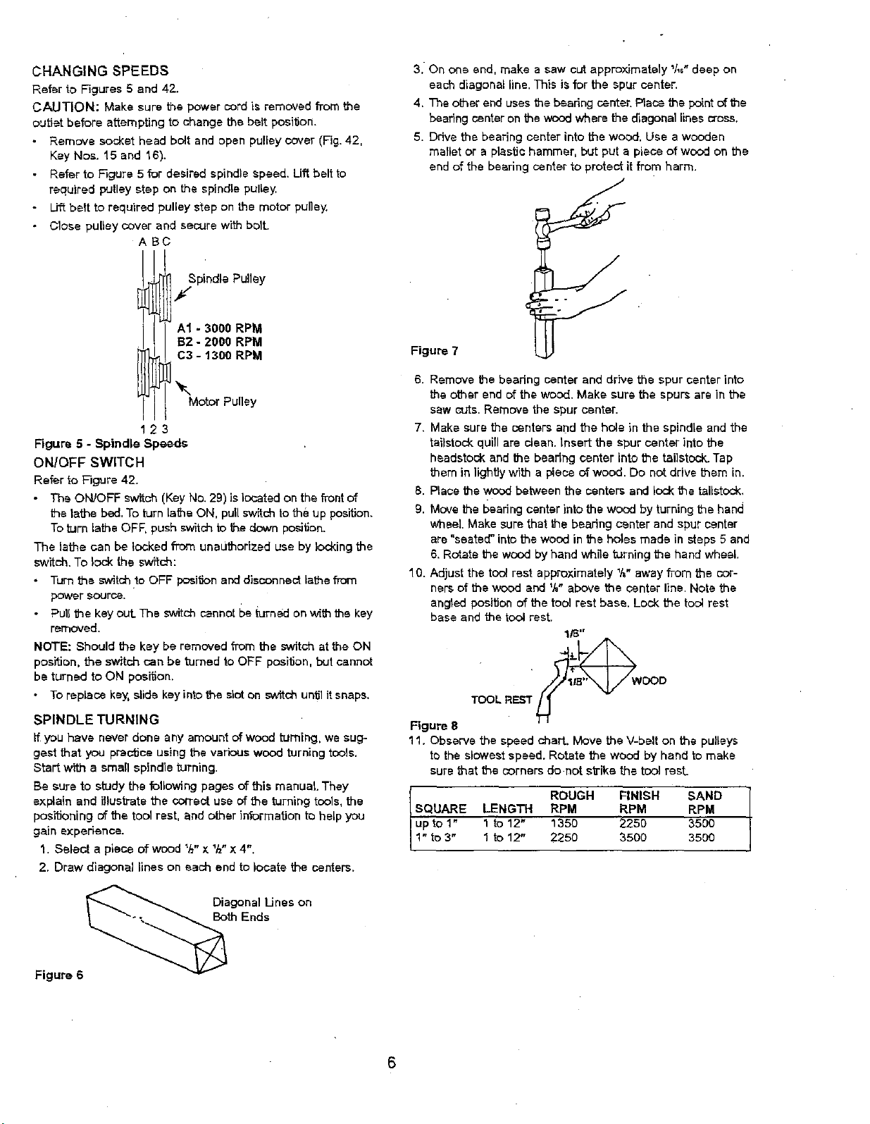
CHANGING SPEEDS
Refer to Figures 5 and 42.
CAUTION: Make sure the power cord is removed from the
outlet before attempting to change the belt post_on.
Remove socket head bolt and open pultey cover (Fig. 42,
Key Nos. t5 and 16).
Refer to F3gure 5 for desired epthdle speed. Lift belt to
required pulley step on the spindle pulley.
Li_ belt to required pulley step on the motor pulley.
Closepulley cover and secure with bolt.
ASC
SpindlePulley
f
3. On one end, make a saw cut approx'_mately l/,s" deep on
each diagonal line. This is for the spur center.
4, The other end uses the bearing center. Place the point of the
beating center on the wood where the _agonal lines cross.
5. Drive the bearing center into the wood, Use a wooden
mstlet or a plastic hammer, but put a piece of wood on the
end of the bearing center to protect it from harm.
- 3000 RPM
B2 - 2000 RPM
C3 - 1300 RPM
Motor Pulley
123
Figure 5 - Spindle Speeds
ON/OFF SWITCH
Refer to Figure 42.
- The ON/OFF switch (Key No. 29) is located on the front of
the rathe bed, To turn lathe ON, pull switch to the up position.
Toturn lathe OFF, push switch to the down pceitic)n.
The lathe can be locked from unauthorized use by locking the
switch, To lock the switch:
• Turn the switch to OFF positionand disconnect lathe from
power source.
• Pull the key out. The switch cannot be 0Jrnedon with the key
removed.
NOTE: Should the key be removed from the switch at the ON
position, the switch can be turned to OFF position, but cannot
be turned to ON position,
• To replace key, slide key into the slot on switchuntil it snaps.
SPINDLE TURNING
If y_u have never done any amount of wood turning, we sug-
gest that you prac'dce using the various wood turning tools.
Start with a small spindle turning.
Be sure to study the following pages of this manual They
explain and iIlusthate the correct use of the turning tools, the
positioning of the tool rest, and other information to help you
gain experience.
1. Select a piece of wood _/_"x 1/_,x 4".
2. Draw diagonal lines on each end to locate the centers,
Figure 7 V
6. Remove the beadng center and drive the spur center into
the other end of the wood. Make sure the spura are in the
saw cuts. Remove the spur center.
7. Make sure the centers and the hole in the spindle and the
tailstock quill are clean. Insert the spur center into the
headstock and the bearing center into the tel]stock. Tap
them in lightly with a piece of wood. Do not drive them in.
8. Place the wood between the centers and lock the tailstock,
9. Move the beating center into the wocd by turning the hand
wheel Make sure that the bearthg center and spur center
are =seated" into the wood in the holes made in steps 5 and
6. Rotate the wood by hand while turning the hand wheel.
10. Adjust the tool rest approximately 1,t,"away from the cor-
ners of the wood and V," above the center llne. Note the
angled position of the tool rest base. Lock the tool rest
base and thetool rest.
TOOLREST wOOD
Figure 8
11. Observe the speed chart. Move the V-belt on the pulleys
tothe slowest speed, Rotate the wood by hand tomake
sure that the corners do not s_ike the tcol rest_
SQUARE ROUGH FINISH SANDLENGTH RPM RPM RPM
upto 1" 1to 12" 1350 2250 3500
1" to 3" 1to 12" 2250 3500 3500
Figure 6
Diagonal Unes on
Both Ends
6
 Loading...