

Craftsman 351219061 Owner’s Manual

Operator's Manual
CRRFTSMI:IN_
HOLLOW CHISEL MORTISER
Model No.
351.219061
CAUTION: Read and follow
all Safety Rules and Operating
Instructions before First Use
of this Product.
Sears, Roebuck and Co., Hoffman Estates, IL 60179 U.S.A.
www.sears.com/craftsman
15140.03 Draft (08/30/02)

Warranty.................................. 2
SafetyRules.............................. 2-3
Unpacking................................. 3
Assembly................................ 3-5
Installation............................... 5-6
Operation................................ 6-8
Maintenance............................. 8-9
PartsIllustrationandList.................. 10-11
Espa5ol............................... 12-19
FULL ONE YEAR WARRANTY
If this product fails due to a defect in material or work-
manship within one year from the date of purchase,
Sears will at its option repair or replace it free of
charge. Contact your nearest Sears Service Center (1-
800-4-MY-HOME) to arrange for product repair, or
return this product to place of purchase for replace-
ment.
If this product is used for commercial or rental purpos-
es, this warranty will apply for 90 days from the date of
purchase.
This warranty applies only while this product is used in
the United States.
This warranty gives you specific legal rights and you
may also have other rights which vary from state to
state.
Sears, Roebuck and Co., Dept. 817WA, Hoffman
Estates, IL 60179
WARNING: For your own safety, read all of the rules
and precautions before operating tool.
CAUTION: Always follow proper operating procedures
as defined in this manual even if you are familiar with
use of this or similar tools. Remember that being care-
less for even a fraction of a second can result in severe
personal injury.
BE PREPARED FOR JOB
• Wear proper apparel. Do not wear loose clothing,
gloves, neckties, rings, bracelets or other jewelry
which may get caught in moving parts of machine.
• Wear protective hair covering to contain long hair.
• Wear safety shoes with non-slip soles.
• Wear safety glasses complying with United States
ANSI Z87.1. Everyday glasses have only impact
resistant lenses. They are NOT safety glasses.
• Wear face mask or dust mask if operation is dusty.
• Be alert and think clearly. Never operate power tools
when tired, intoxicated or when taking medications
that cause drowsiness.
© Sears, Roebuck and Co,
PREPARE WORK AREA FOR JOB
• Keep work area clean. Cluttered work areas invite
accidents.
• Do not use power
• Do not use power
not expose power
• Work area should be properly lighted.
• Proper electrical receptacle should be available for
tool. Three prong plug should be plugged directly
into properly grounded, three-prong receptacle.
• Extension cords should have a grounding prong and
the three wires of the extension cord should be of
the correct gauge.
• Keep visitors at a safe distance from work area.
• Keep children out of workplace. Make workshop child-
proof. Use padlocks, master switches or remove switch
keys to prevent any unintentional use of power tools.
tools in dangerous environments.
tools in damp or wet locations. Do
tools to rain.
TOOL SHOULD BE MAINTAINED
• Always unplug tool prior to inspection.
• Consult manual for specific maintaining and adjust-
ing procedures.
• Keep tool lubricated and clean for safest operation.
• Remove adjusting tools. Form habit of checking to
see that adjusting tools are removed before switch-
ing machine on.
• Keep all parts in working order. Check to determine
that the guard or other parts will operate properly
and perform their intended function.
• Check for damaged parts. Check for alignment of
moving parts, binding, breakage, mounting and any
other condition that may affect a tool's operation.
• A guard or other part that is damaged should be
properly repaired or replaced. Do not perform
makeshift repairs. (Use parts list provided to order
replacement parts.)
KNOW HOW TO USE TOOL
• Use right tool for job. Do not force tool or attachment
to do a job for which it was not designed.
• Disconnect tool when changing blades.
• Avoid accidental start-up. Make sure that the switch
is in the OFF position before plugging in.
• Do not force tool. It will work most efficiently at the
rate for which it was designed.
• Keep hands away from moving parts and cutting
surfaces.
• Never leave tool running unattended. Turn the power
off and do not leave tool until it comes to a complete
stop.
• Do not overreach. Keep proper footing and balance.
• Never stand on tool. Serious injury could occur if tool is
tipped or if blade is unintentionally contacted.
• Know your tool. Learn the tool's operation, applica-
tion and specific limitations.
2
• Use recommended accessories (refer to page 11).
Use of improper accessories may cause risk of
injury to persons.
• Handle workpiece correctly. Protect hands from pos-
sible injury.
• Turn machine off if it jams.
CAUTION: Think safety! Safety is a combination of
operator common sense and alertness at all times
when tool is being used.
WARNING: Do not attempt to operate tool until it is
completely assembled according to the instructions.
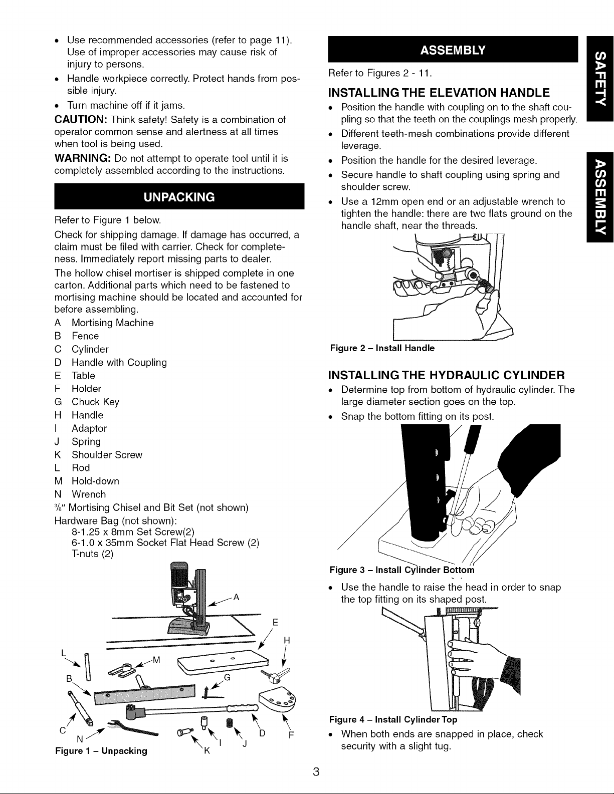
Refer to Figure 1 below.
Check for shipping damage. If damage has occurred, a
claim must be filed with carrier. Check for complete-
ness. Immediately report missing parts to dealer.
The hollow chisel mortiser is shipped complete in one
carton. Additional parts which need to be fastened to
mortising machine should be located and accounted for
before assembling.
A Mortising Machine
B Fence
C Cylinder
D Handle with Coupling
E Table
F Holder
G Chuck Key
H Handle
I Adaptor
J Spring
K Shoulder Screw
L Rod
M Hold-down
N Wrench
3/8"Mortising Chisel and Bit Set (not shown)
Hardware Bag (not shown):
8-1.25 x 8mm Set Screw(2)
6-1.0 x 35mm Socket Flat Head Screw (2)
T-nuts (2)
Refer to Figures 2 - 11.
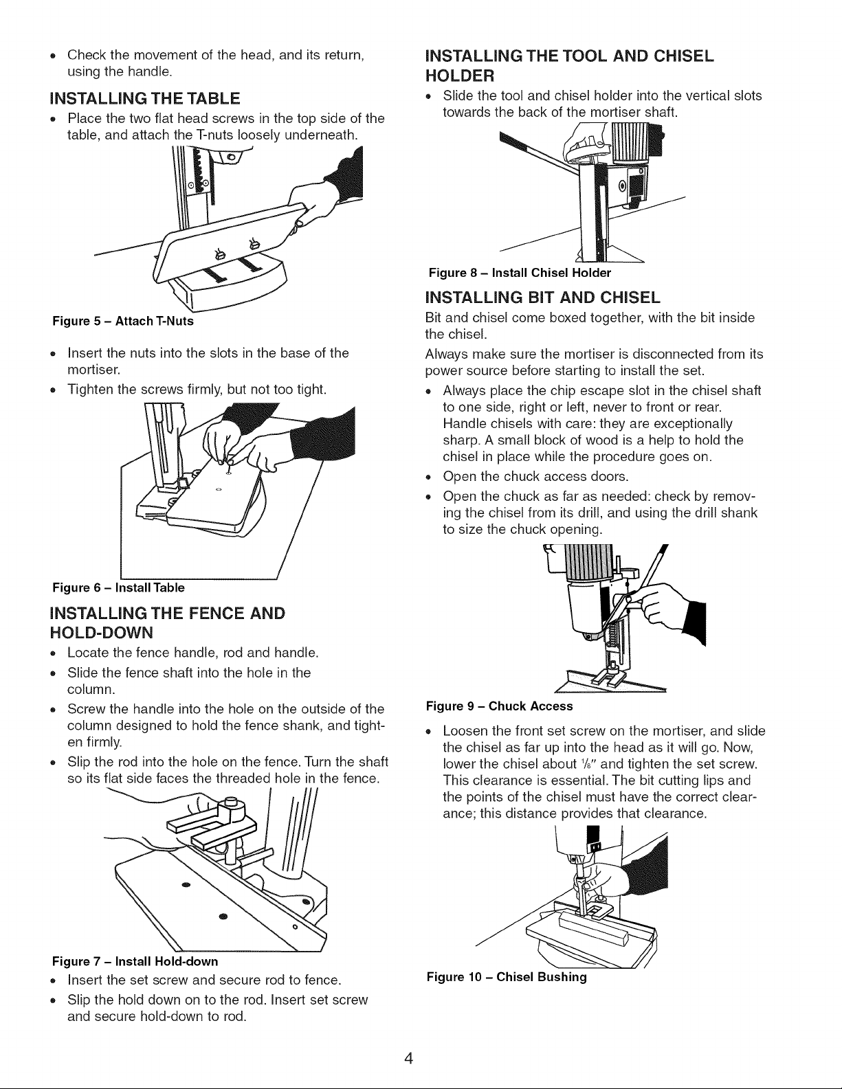
INSTALLING THE ELEVATION HANDLE
• Position the handle with coupling on to the shaft cou-
pling so that the teeth on the couplings mesh properly.
• Different teeth-mesh combinations provide different
leverage.
• Position the handle for the desired leverage.
• Secure handle to shaft coupling using spring and
shoulder screw.
• Use a 12mm open end or an adjustable wrench to
tighten the handle: there are two flats ground on the
handle shaft, near the threads.
Figure 2 - Install Handle
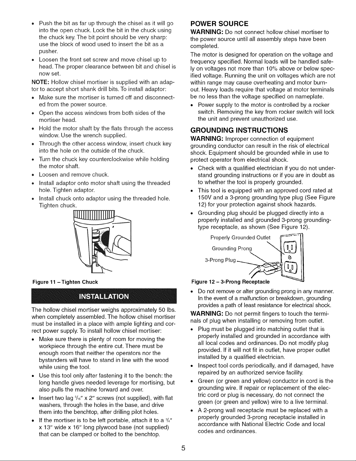
INSTALLING THE HYDRAULIC CYLINDER
• Determine top from bottom of hydraulic cylinder. The
large diameter section goes on the top.
• Snap the bottom fitting on its post.
Figure3 - Install Cylinder Bottom
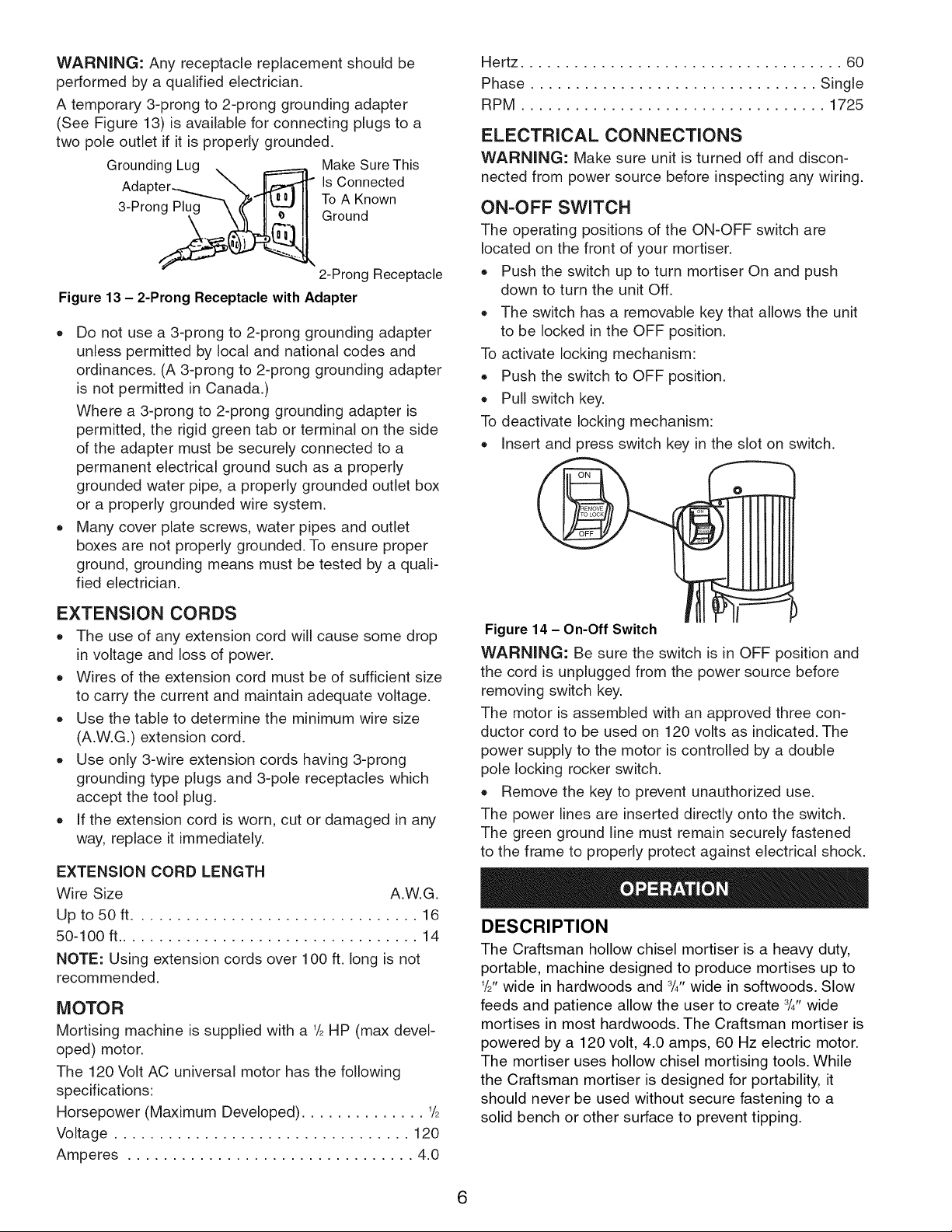
• Use the handle to raise the head in order to snap
the top fitting on its shaped post.
H
Figure 1 - Unpacking
E
Figure 4 - Install Cylinder Top
• When both ends are snapped in place, check
security with a slight tug.
3
• Check the movement of the head, and its return,
using the handle.
INSTALLING THE TABLE
Place the two flat head screws in the top side of the
table, and attach the T-nuts loosely underneath.
Figure 5 - Attach T-Nuts
• Insert the nuts into the slots in the base of the
mortiser.
Tighten the screws firmly, but not too tight.
INSTALLING THE TOOL AND CHISEL
HOLDER
Slide the tool and chisel holder into the vertical slots
towards the back of the mortiser shaft.
Figure 8 - Install Chisel Holder
INSTALLING BIT AND CHISEL
Bit and chisel come boxed together, with the bit inside
the chisel.
Always make sure the mortiser is disconnected from its
power source before starting to install the set.
• Always place the chip escape slot in the chisel shaft
to one side, right or left, never to front or rear.
Handle chisels with care: they are exceptionally
sharp. A small block of wood is a help to hold the
chisel in place while the procedure goes on.
• Open the chuck access doors.
• Open the chuck as far as needed: check by remov-
ing the chisel from its drill, and using the drill shank
to size the chuck opening.
Figure 6 - InstallTable
INSTALLING THE FENCE AND
HOLD-DOWN
• Locate the fence handle, rod and handle.
Slide the fence shaft into the hole in the
column.
Screw the handle into the hole on the outside of the
column designed to hold the fence shank, and tight-
en firmly.
Slip the rod into the hole on the fence. Turn the shaft
so its flat side faces the threaded hole in the fence.
Figure 7 - Install Hold-down
• Insert the set screw and secure rod to fence.
• Slip the hold down on to the rod. Insert set screw
and secure hold-down to rod.
Figure 9 - Chuck Access
Loosen the front set screw on the mortiser, and slide
the chisel as far up into the head as it will go. Now,
lower the chisel about W' and tighten the set screw.
This clearance is essential. The bit cutting lips and
the points of the chisel must have the correct clear-
ance; this distance provides that clearance.
Figure 10 - Chisel Bushing
4
• Push the bit as far up through the chisel as it will go
into the open chuck. Lock the bit in the chuck using
the chuck key. The bit point should be very sharp:
use the block of wood used to insert the bit as a
pusher.
• Loosen the front set screw and move chisel up to
head. The proper clearance between bit and chisel is
now set.
NOTE: Hollow chisel mortiser is supplied with an adap-
tor to accept short shank drill bits. To install adaptor:
• Make sure the morfiser is turned off and disconnect-
ed from the power source.
• Open the access windows from both sides of the
mortiser head.
• Hold the motor shaft by the flats through the access
window. Use the wrench supplied.
• Through the other access window, insert chuck key
into the hole on the outside of the chuck.
• Turn the chuck key counterclockwise while holding
the motor shaft.
• Loosen and remove chuck.
• Install adaptor onto motor shaft using the threaded
hole. Tighten adaptor.
• Install chuck onto adaptor using the threaded hole.
Tighten chuck.
POWER SOURCE
WARNING: Do not connect hollow chisel mortiser to
the power source until all assembly steps have been
completed.
The motor is designed for operation on the voltage and
frequency specified. Normal loads will be handled safe-
ly on voltages not more than 10% above or below spec-
ified voltage. Running the unit on voltages which are not
within range may cause overheating and motor burn-
out. Heavy loads require that voltage at motor terminals
be no less than the voltage specified on nameplate.
. Power supply to the motor is controlled by a rocker
switch. Removing the key from rocker switch will lock
the unit and prevent unauthorized use.
GROUNDING INSTRUCTIONS
WARNING: Improper connection of equipment
grounding conductor can result in the risk of electrical
shock. Equipment should be grounded while in use to
protect operator from electrical shock.
. Check with a qualified electrician if you do not under-
stand grounding instructions or if you are in doubt as
to whether the tool is properly grounded.
. This tool is equipped with an approved cord rated at
150V and a 3-prong grounding type plug (See Figure
12) for your protection against shock hazards.
o Grounding plug should be plugged directly into a
properly installed and grounded 3-prong grounding-
type receptacle, as shown (See Figure 12).
Grounded Outlet
Figure 11 - Tighten Chuck
The hollow chisel mortiser weighs approximately 50 Ibs.
when completely assembled. The hollow chisel mortiser
must be installed in a place with ample lighting and cor-
rect power supply. To install hollow chisel mortiser:
. Make sure there is plenty of room for moving the
workpiece through the entire cut. There must be
enough room that neither the operators nor the
bystanders will have to stand in line with the wood
while using the tool.
. Use this tool only after fastening it to the bench: the
long handle gives needed leverage for mortising, but
also pulls the machine forward and over.
. Insert two lag 5/16"x 2" screws (not supplied), with flat
washers, through the holes in the base, and drive
them into the benchtop, after drilling pilot holes.
. If the mortiser is to be left portable, attach it to a 3/4"
x 13" wide x 16" long plywood base (not supplied)
that can be clamped or bolted to the benchtop.
Grounding Prong
3-Prong Plug
Properly __
Figure 12 - 3-Prong Receptacle
° Do not remove or alter grounding prong in any manner.
Inthe event of a malfunction or breakdown, grounding
provides a path of least resistance for electrical shock.
WARNING: Do not permit fingers to touch the termi-
nals of plug when installing or removing from outlet.
• Plug must be plugged into matching outlet that is
properly installed and grounded in accordance with
all local codes and ordinances. Do not modify plug
provided. If it will not fit in outlet, have proper outlet
installed by a qualified electrician.
• Inspect tool cords periodically, and if damaged, have
repaired by an authorized service facility.
• Green (or green and yellow) conductor in cord is the
grounding wire. If repair or replacement of the elec-
tric cord or plug is necessary, do not connect the
green (or green and yellow) wire to a live terminal.
• A 2-prong wall receptacle must be replaced with a
properly grounded 3-prong receptacle installed in
accordance with National Electric Code and local
codes and ordinances.
5
WARNING: Any receptacle replacement should be
performed by a qualified electrician.
A temporary 3-prong to 2-prong grounding adapter
(See Figure 13) is available for connecting plugs to a
two pole outlet if it is properly grounded.
Make Sure This
Grounding Lug _ Is Connected
To A Known
3-Prong Plug Ground
2-Prong Receptacle
Figure 13 - 2-Prong Receptacle with Adapter
• Do not use a 3-prong to 2-prong grounding adapter
unless permitted by local and national codes and
ordinances. (A 3-prong to 2-prong grounding adapter
is not permitted in Canada.)
Where a 3-prong to 2-prong grounding adapter is
permitted, the rigid green tab or terminal on the side
of the adapter must be securely connected to a
permanent electrical ground such as a properly
grounded water pipe, a properly grounded outlet box
or a properly grounded wire system.
Many cover plate screws, water pipes and outlet
boxes are not properly grounded. To ensure proper
ground, grounding means must be tested by a quali-
fied electrician.
Hertz .................................... 60
Phase ................................ Single
RPM .................................. 1725
ELECTRICAL CONNECTIONS
WARNING: Make sure unit is turned off and discon-
nected from power source before inspecting any wiring.
ON-OFF SWITCH
The operating positions of the ON-OFF switch are
located on the front of your mortiser.
Push the switch up to turn mortiser On and push
down to turn the unit Off.
The switch has a removable key that allows the unit
to be locked in the OFF position.
To activate locking mechanism:
Push the switch to OFF position.
Pull switch key.
To deactivate locking mechanism:
insert and press switch key in the slot on switch.
EXTENSION CORDS
• The use of any extension cord will cause some drop
in voltage and loss of power.
• Wires of the extension cord must be of sufficient size
to carry the current and maintain adequate voltage.
• Use the table to determine the minimum wire size
(A.W.G.) extension cord.
• Use only 3-wire extension cords having 3-prong
grounding type plugs and 3-pole receptacles which
accept the tool plug.
If the extension cord is worn, cut or damaged in any
way, replace it immediately.
EXTENSION CORD LENGTH
Wire Size A.W.G.
Up to 50 ft ................................ 16
50-100 ft.................................. 14
NOTE: Using extension cords over 100 ft. long is not
recommended.
MOTOR
Mortising machine is supplied with a 1/_HP (max devel-
oped) motor.
The 120 Volt AC universal motor has the following
specifications:
Horsepower (Maximum Developed) .............. 1/_
Voltage ................................. 120
Amperes ................................ 4.0
Figure 14 - On-Off Switch
WARNING: Be sure the switch is in OFF position and
the cord is unplugged from the power source before
removing switch key.
The motor is assembled with an approved three con-
ductor cord to be used on 120 volts as indicated. The
power supply to the motor is controlled by a double
pole locking rocker switch.
Remove the key to prevent unauthorized use.
The power lines are inserted directly onto the switch.
The green ground line must remain securely fastened
to the frame to properly protect against electrical shock.
DESCRIPTION
The Craftsman hollow chisel mortiser is a heaw duty,
portable, machine designed to produce mortises up to
_/2"wide in hardwoods and 3/4"wide in softwoods. Slow
feeds and patience allow the user to create 3/4"wide
mortises in most hardwoods. The Craftsman mortiser is
powered by a 120 volt, 4.0 amps, 60 Hz electric motor.
The mortiser uses hollow chisel mortising tools. While
the Craftsman mortiser is designed for portability, it
should never be used without secure fastening to a
solid bench or other surface to prevent tipping.
6
 Loading...