

Craftsman 351217881 Owner’s Manual

Operator's Manual /
CRFIF MFIN°I
1/8tr
Bench Top
JOINTER/PLANER
Model No.
351.21 7881
CAUTION: Read and follow
all Safety Rules and Operating
Instructions before First Use
of this Product.
Sears, Roebuck and Co., Hoffman Estates, IL 60179 U.S.A.
www.sears.com/craftsman
23719.02 Draft (03/20/07)
Warranty.................................... 2
SafetyRules............................... 2-3
Unpacking.................................. 3
Assembly................................. 3-4
Installation................................. 4-6
Operation................................. 6-9
Maintenance.............................. 9-11
Troubleshooting............................. 12
PartsIllustrationandList................... 14-17
Espa_ol................................. 18-31
ONE-YEAR FULL WARRANTY ON
CRAFTSMAN PROFESSIONAL TOOL
If this Craftsman tool fails due to a defect in material or
workmanship within one year from the date of purchase,
call 1-800-4-MY-HOME® TO ARRANGE FOR FREE
REPAIR (or replacement if repair proves impossible).
This warranty does not include expendable parts, such
as lamps, batteries, bits or blades.
If this tool is ever used for commercial or rental purposes,
this warranty will apply for only 90 days from the date of
purchase.
This warranty gives you specific legal rights and you may
also have other rights which vary from state to state.
Sears, Roebuck and Co., Hoffman Estates, IL 60179
BE PREPARED FOR JOB
• Wear proper apparel. Do not wear loose clothing,
gloves, neckties, rings, bracelets or other jewelry
which may get caught in moving parts of machine.
• Wear protective hair covering to contain long hair.
• Wear safety shoes with non-slip soles.
• Wear safety glasses complying with United States
ANSI Z87.1. Everyday glasses have only impact
resistant lenses. They are NOT safety glasses.
• Wear face mask or dust mask if operation is dusty.
• Be alert and think clearly. Never operate power tools
when tired, intoxicated or when taking medications
that cause drowsiness.
PREPARE WORK AREA FOR JOB
• Keep work area clean. Cluttered work areas invite
accidents.
• Do not use power tools in dangerous environments.
• Do not use power tools in damp or wet locations. Do
not expose power tools to rain.
• Work area should be properly lighted.
• Proper electrical receptacle should be available for
tool. Three prong plug should be plugged directly
into properly grounded, three-prong receptacle.
• Extension cords should have a grounding prong and
the three wires of the extension cord should be of
the correct gauge.
• Keep visitors at a safe distance from work area.
• Keep children out of workplace. Make workshop child-
proof. Use padlocks, master switches or remove switch
keys to prevent any unintentional use of power tools.
WARNING: For your own safety, read all of the rules
and precautions before operating tool.
WARNING: Some dust created by power sanding,
sawing, grinding, drilling and other construction activi-
ties contains chemicals known to cause cancer, birth
defects or other reproductive harm.
Some examples of these chemicals are:
• Lead from lead-based paints.
• Crystalline silica from bricks and cement and other
masonry products.
• Arsenic and chromium from chemically-treated lumber.
Your risk from these exposures vary, depending on how
often you do this type of work. To reduce your exposure
to these chemicals: work in a well ventilated area and
work with approved safety equipment. Always wear
OSHA/NIOSH approved, properly fitting face mask or
respirator when using such tools.
CAUTION: Always follow proper operating procedures
as defined in this manual even if you are familiar with
use of this or similar tools. Remember that being care-
less for even a fraction of a second can result in severe
personal injury.
TOOL SHOULD BE MAINTAINED
• Always unplug tool prior to inspection.
• Consult manual for specific maintaining and adjust-
ing procedures.
• Keep tool lubricated and clean for safest operation.
• Remove adjusting tools. Form habit of checking to
see that adjusting tools are removed before switch-
ing machine on.
• Keep all parts in working order. Check to determine
that the guard or other parts will operate properly
and perform their intended function.
• Check for damaged parts. Check for alignment of
moving parts, binding, breakage, mounting and any
other condition that may affect a tool's operation.
• A guard or other part that is damaged should be
properly repaired or replaced. Do not perform
makeshift repairs. (Use parts list provided to order
replacement parts.)
KNOW HOW TO USE TOOL
• Use right tool for job. Do not force tool or attachment
to do a job for which it was not designed.
• Disconnect tool when changing blades.
© Sears, Roebuck and Co. 2
• Avoid accidental start-up. Make sure that the switch
is in the OFF position before plugging in.
• Do not force tool. It will work most efficiently at the
rate for which it was designed.
• Keep hands away from moving parts and cutting
surfaces.
• Never leave tool running unattended. Turn the power
off and do not leave tool until it comes to a complete
stop.
• Do not overreach. Keep proper footing and balance.
• Never stand on tool. Serious injury could occur if tool is
tipped or if blade is unintentionally contacted.
• Know your tool. Learn the tool's operation, applica-
tion and specific limitations.
• Use recommended accessories (refer to page 17).
Use of improper accessories may cause risk of
injury to persons.
• Handle workpiece correctly. Protect hands from pos-
sible injury.
• Turn machine off if it jams. Blade jams when it digs
too deeply into workpiece. (Motor force keeps it
stuck in the work.)
• Always keep drive, cutterhead and blade guards in
place and in proper operating condition.
• Feed work into blade or cutter against direction of
rotation.
CAUTION: Think safety! Safety is a combination of
operator common sense and alertness at all times
when tool is being used.
WARNING: Do not attempt to operate tool until it is
completely assembled according to the instructions.
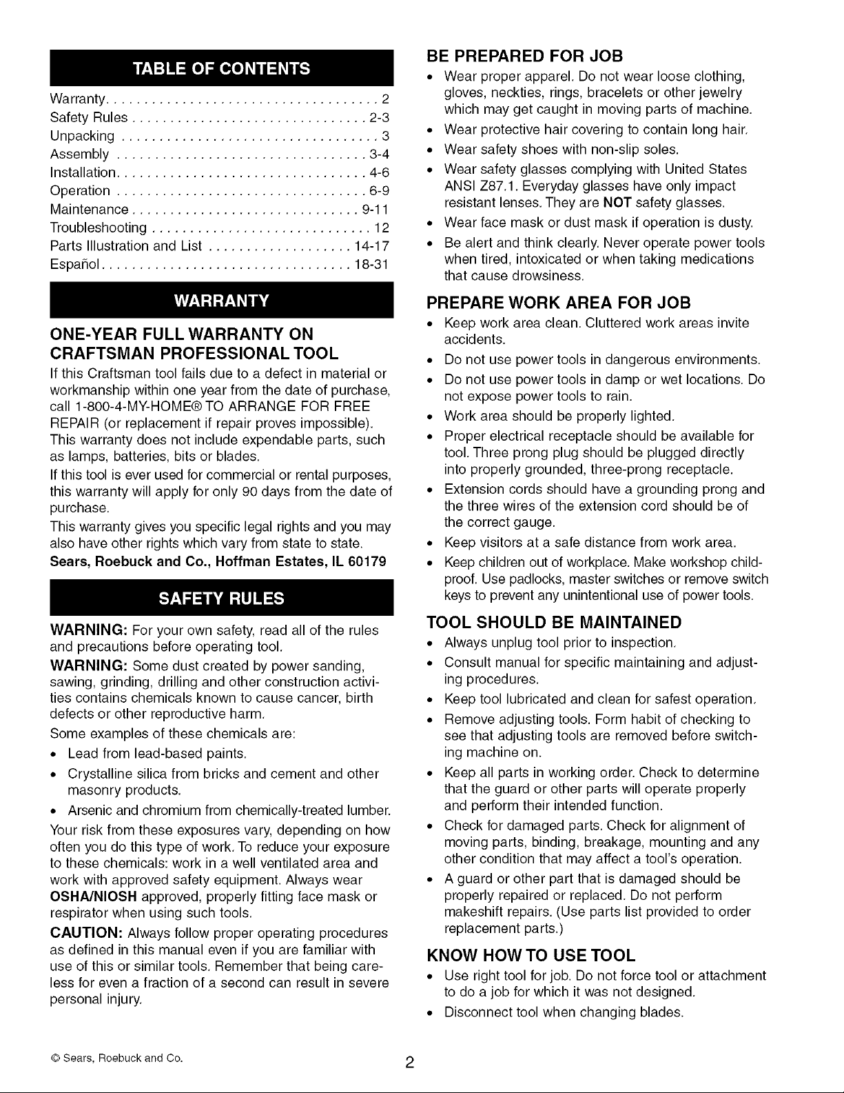
Figure 1 - Unpacking
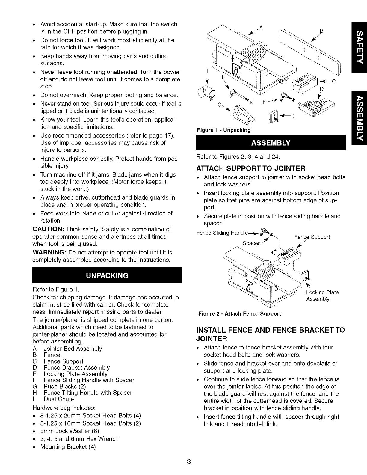
Refer to Figures 2, 3, 4 and 24.
ATTACH SUPPORT TO JOINTER
• Attach fence support to jointer with socket head bolts
and lock washers.
• Insert locking plate assembly into support. Position
plate so that pins are against bottom edge of sup-
port.
• Secure plate in position with fence sliding handle and
spacer.
Fence Sliding Handle_ _;_
Spacer_" "_ /
Fence
Support
Refer to Figure 1.
Check for shipping damage. If damage has occurred, a
claim must be filed with carrier. Check for complete-
ness. Immediately report missing parts to dealer.
The jointer/planer is shipped complete in one carton.
Additional parts which need to be fastened to
jointer/planer should be located and accounted for
before assembling.
A Jointer Bed Assembly
B Fence
C Fence Support
D Fence Bracket Assembly
E Locking Plate Assembly
F Fence Sliding Handle with Spacer
G Push Blocks (2)
H Fence Tilting Handle with Spacer
I Dust Chute
Hardware bag includes:
• 8-1.25 x 20mm Socket Head Bolts (4)
• 8-1.25 x 16mm Socket Head Bolts (2)
• 8mm Lock Washer (6)
• 3, 4, 5 and 6mm HexWrench
• Mounting Bracket (4)
L_ocking Plate
Assembly
Figure 2 - Attach Fence Support
INSTALL FENCE AND FENCE BRACKET TO
JOINTER
• Attach fence to fence bracket assembly with four
socket head bolts and lock washers.
• Slide fence and bracket over and onto dovetails of
support and locking plate.
• Continue to slide fence forward so that the fence is
over the jointer tables. At this position the edge of
the blade guard will rest against the fence, and the
entire width of the cutterhead is covered. Secure
bracket in position with fence sliding handle.
• Insert fence tilting handle with spacer through right
link and thread into left link.
Fence Tilting _
Handle _.
Figure 3 - Attach Fence Assembly
• Make sure limit plate (Figure 4, page 4) is resting in
slot of block. Position fence against shaft and lock
fence in position with fence tilting handle.
• Place a combination square against face of fence
and table surface. The fence and table must be at
90° to each other. If not, loosen tilting handle, loosen
hex nut and turn shaft with a screw driver until fence
is square. Secure in position by tightening hex nut.
• Use a bevel gauge or protractor to check 45° inward
and outward limit stops. The 45° inward stop is the
hex head bolt located beneath the shaft. The 45 °
outward stop is located at the top of the fence. If
adjustment is needed, loosen hex nut, turn hex head
bolt to proper position and secure in place with hex
nut.
Block
Limit Plate__ Hex Nut
Fence Bracket
ty
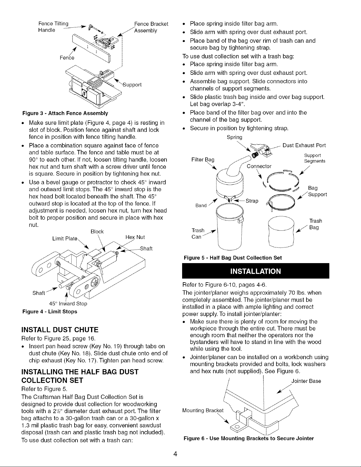
• Place spring inside filter bag arm.
• Slide arm with spring over dust exhaust port.
• Place band of the bag over rim of trash can and
secure bag by tightening strap.
To use dust collection set with a trash bag:
• Place spring inside filter bag arm.
• Slide arm with spring over dust exhaust port.
• Assemble bag support. Slide connectors into
channels of support segments.
• Slide plastic trash bag inside and over bag support.
Let bag overlap 3-4".
• Place band of the filter bag over and into the
channel of the bag support.
• Secure in position by tightening strap.
Spring
_.4__ Dust Exhaust Port
_. _ _ _'_:_' Support
i--tlter_ag _..._ Segments
_, f / Connector /
k - J Bag
_/Support
/I_ _Strap /_
Baod
45° Stop
Figure 4 - Limit Stops
INSTALL DUST CHUTE
Refer to Figure 25, page 16.
• Insert pan head screw (Key No. 19) through tabs on
dust chute (Key No. 18). Slide dust chute onto end of
chip exhaust (Key No. 17). Tighten pan head screw.
INSTALLING THE HALF BAG DUST
COLLECTION SET
Refer to Figure 5.
The Craftsman Half Bag Dust Collection Set is
designed to provide dust collection for woodworking
tools with a 21/2"diameter dust exhaust port. The filter
bag attachs to a 30-gallon trash can or a 30-gallon x
1.3 mil plastic trash bag for easy, convenient sawdust
disposal (trash can and plastic trash bag not included).
To use dust collection set with a trash can:
Figure 5 - Half Bag Dust Collection Set
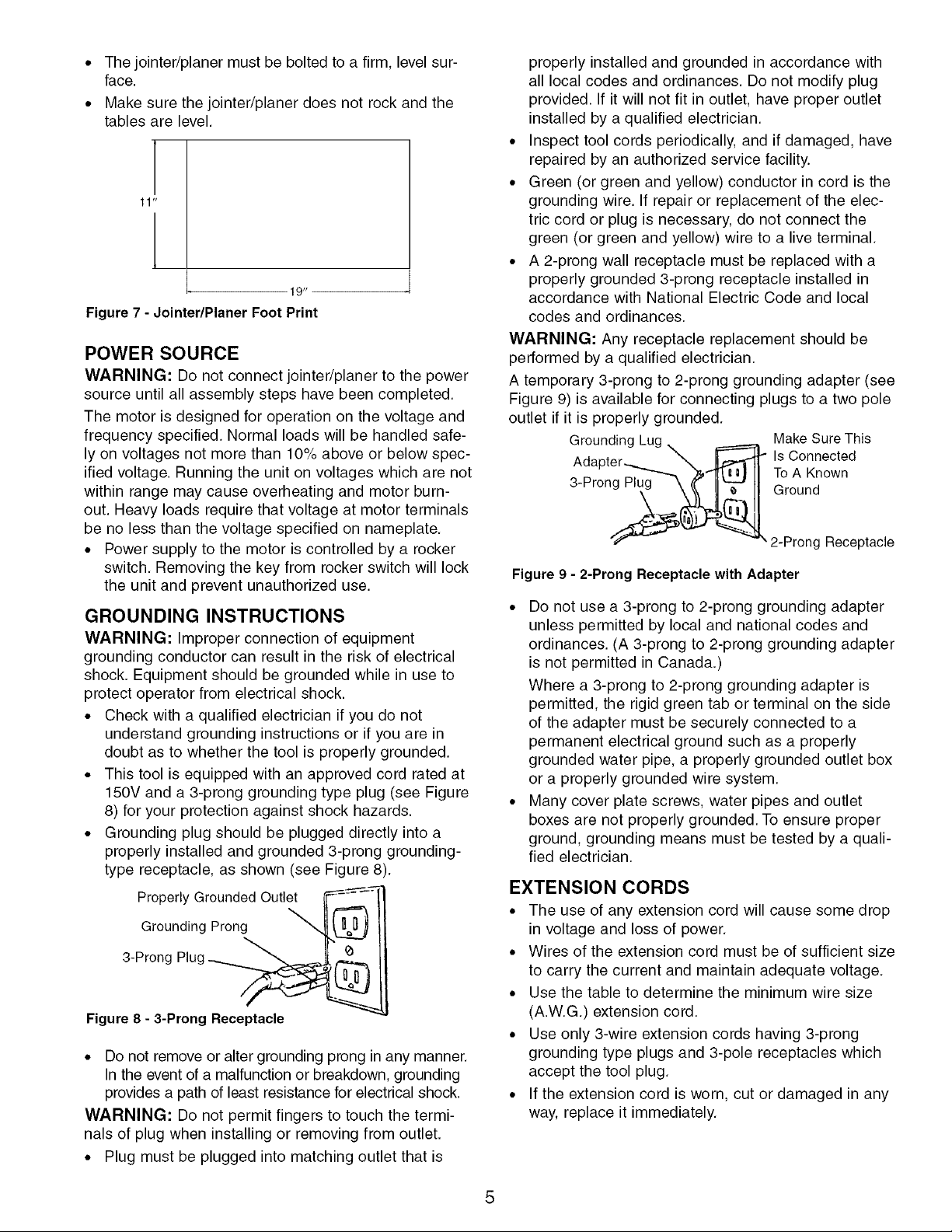
Refer to Figure 6-10, pages 4-6.
The jointer/planer weighs approximately 70 Ibs. when
completely assembled. The jointer/planer must be
installed in a place with ample lighting and correct
power supply. To install jointer/planter:
• Make sure there is plenty of room for moving the
workpiece through the entire cut. There must be
enough room that neither the operators nor the
bystanders will have to stand in line with the wood
while using the tool.
• Jointer/planer can be installed on a workbench using
mounting brackets provided and bolts, lock washers
and hex nuts (not supplied). See Figure 6.
Jointer Base
Mounting Bracket
\
Figure 6 - Use Mounting Brackets to Secure Jointer
4
• The jointer/planer must be bolted to a firm, level sur-
face.
• Make sure the jointer/planer does not rock and the
tables are level.
11 _
I* 19"
Figure 7 - Jointer/Planer Foot Print
POWER SOURCE
WARNING: Do not connect jointer/planer to the power
source until all assembly steps have been completed.
The motor is designed for operation on the voltage and
frequency specified. Normal loads will be handled safe-
ly on voltages not more than 10% above or below spec-
ified voltage. Running the unit on voltages which are not
within range may cause overheating and motor burn-
out. Heavy loads require that voltage at motor terminals
be no less than the voltage specified on nameplate.
• Power supply to the motor is controlled by a rocker
switch. Removing the key from rocker switch will lock
the unit and prevent unauthorized use.
GROUNDING INSTRUCTIONS
WARNING: Improper connection of equipment
grounding conductor can result in the risk of electrical
shock. Equipment should be grounded while in use to
protect operator from electrical shock.
• Check with a qualified electrician if you do not
understand grounding instructions or if you are in
doubt as to whether the tool is properly grounded.
• This tool is equipped with an approved cord rated at
150V and a 3-prong grounding type plug (see Figure
8) for your protection against shock hazards.
• Grounding plug should be plugged directly into a
properly installed and grounded 3-prong grounding-
type receptacle, as shown (see Figure 8).
Grounded Outlet
Grounding Prong
3-Prong Plug
Properly __
Figure 8 - 3-Prong Receptacle
• Do not remove or alter grounding prong in any manner.
In the event of a malfunction or breakdown, grounding
provides a path of least resistance for electrical shock.
WARNING: Do not permit fingers to touch the termi-
nals of plug when installing or removing from outlet.
• Plug must be plugged into matching outlet that is
properly installed and grounded in accordance with
all local codes and ordinances. Do not modify plug
provided. If it will not fit in outlet, have proper outlet
installed by a qualified electrician.
• Inspect tool cords periodically, and if damaged, have
repaired by an authorized service facility.
• Green (or green and yellow) conductor in cord is the
grounding wire. If repair or replacement of the elec-
tric cord or plug is necessary, do not connect the
green (or green and yellow) wire to a live terminal.
• A 2-prong wall receptacle must be replaced with a
properly grounded 3-prong receptacle installed in
accordance with National Electric Code and local
codes and ordinances.
WARNING: Any receptacle replacement should be
performed by a qualified electrician.
A temporary 3-prong to 2-prong grounding adapter (see
Figure 9) is available for connecting plugs to a two pole
outlet if it is properly grounded.
Make Sure This
Grounding Lug_ _ Is Connected
Adapter-_._._ _ ToA Known
3-Pron__ Ground
2-Prong Receptacle
Figure 9 - 2-Prong Receptacle with Adapter
• Do not use a 3-prong to 2-prong grounding adapter
unless permitted by local and national codes and
ordinances. (A 3-prong to 2-prong grounding adapter
is not permitted in Canada.)
Where a 3-prong to 2-prong grounding adapter is
permitted, the rigid green tab or terminal on the side
of the adapter must be securely connected to a
permanent electrical ground such as a properly
grounded water pipe, a properly grounded outlet box
or a properly grounded wire system.
• Many cover plate screws, water pipes and outlet
boxes are not properly grounded. To ensure proper
ground, grounding means must be tested by a quali-
fied electrician.
EXTENSION CORDS
• The use of any extension cord will cause some drop
in voltage and loss of power.
• Wires of the extension cord must be of sufficient size
to carry the current and maintain adequate voltage.
• Use the table to determine the minimum wire size
(A.W.G.) extension cord.
• Use only 3-wire extension cords having 3-prong
grounding type plugs and 3-pole receptacles which
accept the tool plug.
• If the extension cord is worn, cut or damaged in any
way, replace it immediately.

EXTENSIONCORDLENGTH
WireSize A.W.G.
Upto50ft.................................. 16
50-100ft................................... 14
NOTE:Usingextensioncordsover100ft.longisnot
recommended.
MOTOR
The 120 Volt AC universal motor has the following
specifications:
Voltage ................................... 120
Amps ..................................... 12
Hertz ..................................... 60
Phase .................................. Single
Cutterhead RPM ......................... 10,000
ELECTRICAL CONNECTIONS
WARNING: Make sure unit is turned off and discon-
nected from power source before inspecting any wiring.
The motor is assembled with an approved three con-
ductor cord to be used on 120 volts as indicated. The
power supply to the motor is controlled by a double
pole locking rocker switch.
• Remove the key to prevent unauthorized use.
The power lines are inserted directly onto the switch.
The green ground line must remain securely fastened
to the frame to properly protect against electrical shock.
Refer to Figures 10-20, pages 7-9.
DESCRIPTION
Craftsman 61/8'' jointer/planer is used to surface the
faces and edges of boards, produce a flat surface on
warped boards and shape bevels, chamfers and tapers.
The jointer/planer features cast iron infeed and outfeed
tables, cast iron body with smooth work surfaces and
lead screws for precise table height adjustment.
Balanced guide fence tilts 45 ° (inward) and 45 ° (out-
ward). Built-in blower for chip removal. Tool comes with
locking rocker switch with removable key and push
blocks. Jointer/planer easily handles rough-cut lumber,
planes hard and soft woods up to 61/8'' wide using a two
blade cutterhead, and takes cuts up to 1/8".
SPECIFICATIONS
Table size ............................ 285/8x 61/4"
Fence size ........................... 22%x 33/4"
Blade width ............................... 61/J'
Maximum cut........................... 1/8"Deep
Cuts Per Minute ......................... 20,000
Overall Size ....................... 285/8x 18 x 12"
Dust collection port .................. 2V2"Diameter
Weight .................................. 70 Ibs
Motor ............................... 12A, 120V
OPERATION SAFETY RULES
Jointing is a surfacing operation in which a small
amount of wood is removed from the edges and faces
of boards to get smooth, straight and even surfaces
such that the two edges that run across the planing
blocks would fit together perfectly, forming a seamless
joint.
Planing refers to the sizing of lumber to a desired thick-
ness while creating a level surface parallel to the oppo-
site size of the board. Depth of cut is the term used to
indicate how deep the blades will cut into the workpiece.
WARNING: Operation of any power tool can result in
foreign objects being thrown into eyes which can result
in severe eye damage. Always wear safety goggles
complying with United States ANSI Z87.1 (shown on
package) before commencing power tool operation.
WARNING: For your own safety, read all of the
instructions and safety precautions before operating
tool.
• Know general power tool safety. Make sure all pre-
cautions are understood (see pages 2, 3 and 6).
• Whenever adjusting or replacing any parts on
jointer/planer, turn switch off and remove plug from
power source.
• Make sure all guards are properly attached and
securely fastened.
• Make sure all moving parts are free from interference.
• Always wear eye protection or face shield.
• Make sure blades are aligned and properly attached
to cutterhead.
• Do not plug in jointer/planer unless switch is in OFF
position. After turning switch on, allow jointer/planer
to come to full speed before operating.
• Keep hands clear of all moving parts.
• Do not force cut. Slowing or stalling will overheat
motor.
• Use quality lumber. Blades last longer and cuts are
smoother with good quality wood.
• Do not perform jointing/planing operations on materi-
al shorter than 8W', narrower than 3/4",or less than
1/4"thick
• Never make jointing cut deeper than 1/8".
• Always keep cutterhead and blade guards in proper
working condition.
• Maintain the proper relationships of infeed and out-
feed table surfaces and cutterhead blade path.
• Do not back the work toward the infeed table.
• Support the workpiece adequately at all times during
operation; maintain control of the workpiece.
• Use hold-down/push blocks for jointing material nar-
rower than 3" or planing material thinner than 3".
• Take precautions against kickback. Do not permit any-
one to stand or cross in line of cutterhead's rotation.
Kickback or thrown debris will travel in this direction.
6
• Turn switch off and disconnect power whenever
jointer/planer is not in use.
• Replace or sharpen blades as they become damaged
or dull.
• Do not attempt to perform an abnormal or little used
operation without study and the use of adequate hold-
down/push blocks, jigs, fixtures, stops and the like.
• Keep jointer/planer maintained. Follow maintenance
instructions (see pages 10-11).
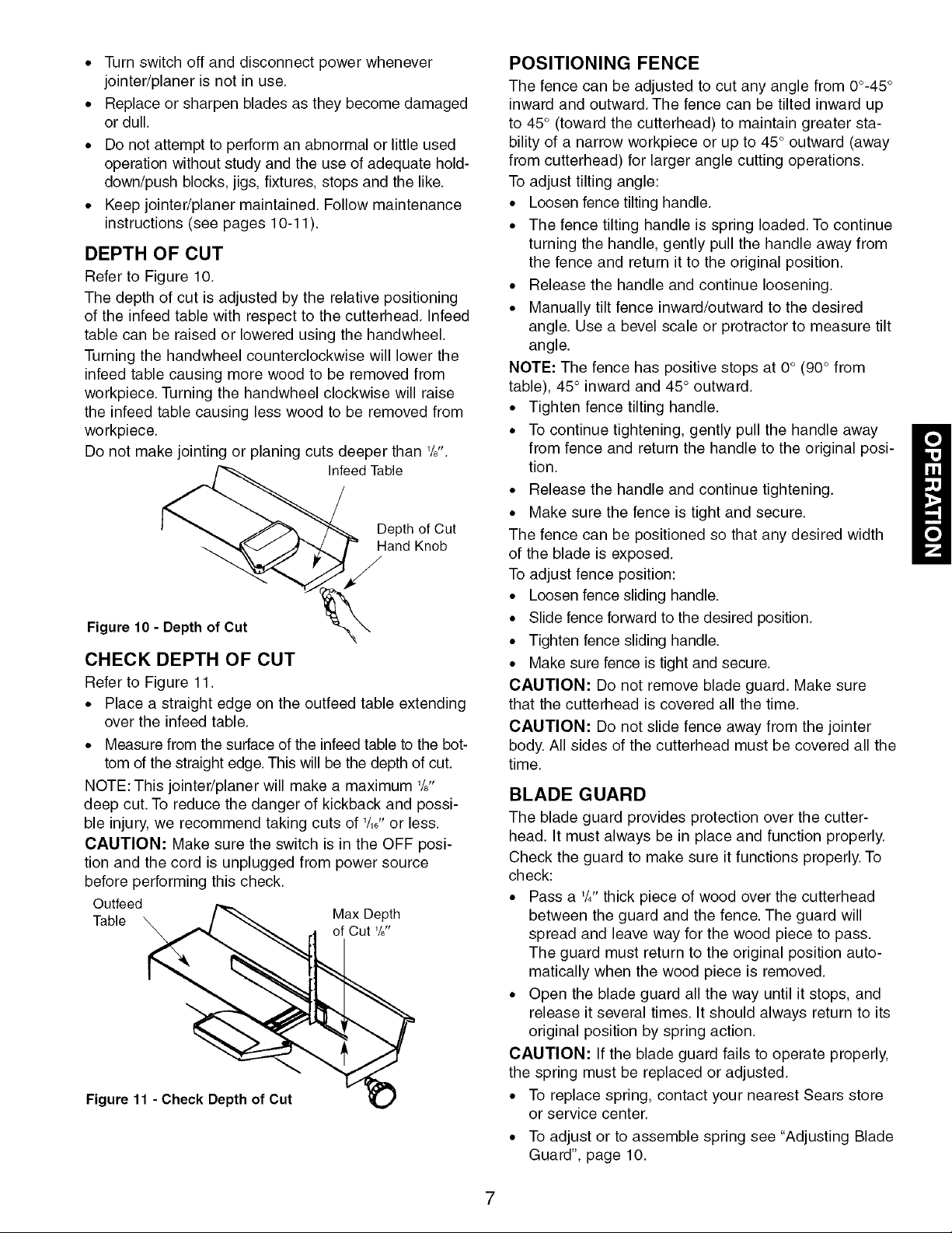
DEPTH OF CUT
Refer to Figure 10.
The depth of cut is adjusted by the relative positioning
of the infeed table with respect to the cutterhead. Infeed
table can be raised or lowered using the handwheel.
Turning the handwheel counterclockwise will lower the
infeed table causing more wood to be removed from
workpiece. Turning the handwheel clockwise will raise
the infeed table causing less wood to be removed from
workpiece.
Do not make jointing or planing cuts deeper than 1/8".
Infeed Table
Depth of Cut
Hand Knob
Figure 10 - Depth of Cut
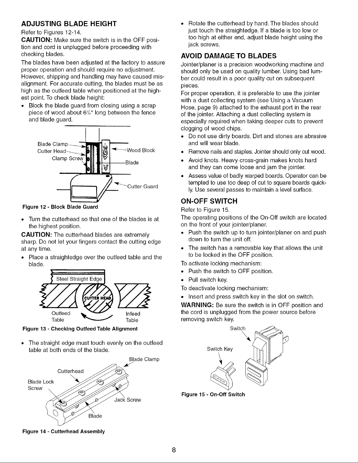
CHECK DEPTH OF CUT
Refer to Figure 11.
• Place a straight edge on the outfeed table extending
over the infeed table.
• Measure from the surface of the infeed table to the bot-
tom of the straight edge. This will be the depth of cut.
NOTE: This jointer/planer will make a maximum 1/8"
deep cut. To reduce the danger of kickback and possi-
ble injury, we recommend taking cuts of 1/16"or less.
CAUTION: Make sure the switch is in the OFF posi-
tion and the cord is unplugged from power source
before performing this check.
Outfeed
f Cut _/8"
T xeth
Figure 11 - Check Depth of Cut _.)
POSITIONING FENCE
The fence can be adjusted to cut any angle from 0o-45°
inward and outward. The fence can be tilted inward up
to 45° (toward the cutterhead) to maintain greater sta-
bility of a narrow workpiece or up to 45° outward (away
from cutterhead) for larger angle cutting operations.
To adjust tilting angle:
• Loosen fence tilting handle.
• The fence tilting handle is spring loaded. To continue
turning the handle, gently pull the handle away from
the fence and return it to the original position.
• Release the handle and continue loosening.
• Manually tilt fence inward/outward to the desired
angle. Use a bevel scale or protractor to measure tilt
angle.
NOTE: The fence has positive stops at 0° (90° from
table), 45 ° inward and 45 ° outward.
• Tighten fence tilting handle.
• To continue tightening, gently pull the handle away
from fence and return the handle to the original posi-
tion.
• Release the handle and continue tightening.
• Make sure the fence is tight and secure.
The fence can be positioned so that any desired width
of the blade is exposed.
To adjust fence position:
• Loosen fence sliding handle.
• Slide fence forward to the desired position.
• Tighten fence sliding handle.
• Make sure fence is tight and secure.
CAUTION: Do not remove blade guard. Make sure
that the cutterhead is covered all the time.
CAUTION: Do not slide fence away from the jointer
body. All sides of the cutterhead must be covered all the
time.
BLADE GUARD
The blade guard provides protection over the cutter-
head. It must always be in place and function properly.
Check the guard to make sure it functions properly. To
check:
• Pass a 1/4"thick piece of wood over the cutterhead
between the guard and the fence. The guard will
spread and leave way for the wood piece to pass.
The guard must return to the original position auto-
matically when the wood piece is removed.
• Open the blade guard all the way until it stops, and
release it several times. It should always return to its
original position by spring action.
CAUTION: If the blade guard fails to operate properly,
the spring must be replaced or adjusted.
• To replace spring, contact your nearest Sears store
or service center.
• To adjust or to assemble spring see "Adjusting Blade
Guard", page 10.
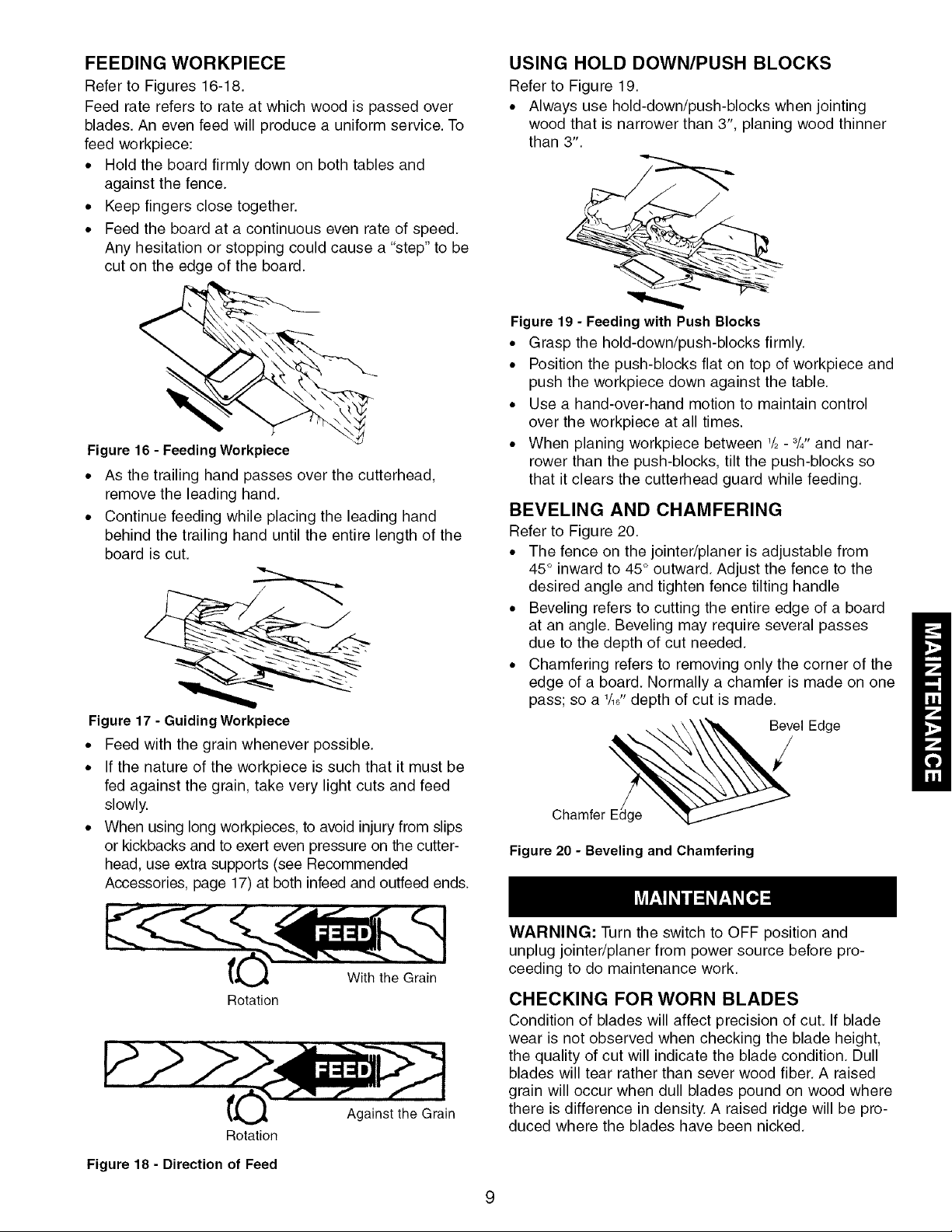
ADJUSTING BLADE HEIGHT
Refer to Figures 12-14.
CAUTION: Make sure the switch is in the OFF posi-
tion and cord is unplugged before proceeding with
checking blades.
The blades have been adjusted at the factory to assure
proper operation and should require no adjustment.
However, shipping and handling may have caused mis-
alignment. For accurate cutting, the blades must be as
high as the outfeed table when positioned at the high-
est point. To check blade height:
• Block the blade guard from closing using a scrap
piece of wood about 61/4"long between the fence
and blade guard.
Blade Clam
Clamp
Rotate the cutterhead by hand. The blades should
just touch the straightedge. If a blade is too low or
too high at either end, adjust blade height using the
jack screws.
AVOID DAMAGE TO BLADES
Jointer/planer is a precision woodworking machine and
should only be used on quality lumber. Using bad lum-
ber could result in a poor quality cut on subsequent
pieces.
For proper operation, it is preferable to use the jointer
with a dust collecting system (see Using a Vacuum
Hose, page 9) attached to the exhaust port in the rear
of the jointer. Attaching a dust collecting system is
especially required when taking deeper cuts to prevent
clogging of wood chips.
• Do not use dirty boards. Dirt and stones are abrasive
and will wear blade.
• Remove nails and staples. Jointer should only cut wood.
• Avoid knots. Heavy cross-grain makes knots hard
and they can come loose and jam the jointer.
• Assess value of badly warped boards. Operator can be
tempted to use too deep of cut to square boards quick-
ly. Use several passes to maintain a level surface.
Figure 12 - Block Blade Guard
• Turn the cutterhead so that one of the blades is at
the highest position.
CAUTION: The cutterhead blades are extremely
sharp. Do not let your fingers contact the cutting edge
at any time.
• Place a straightedge over the outfeed table and the
blade.
I
Steel Straight Edge I
_Ou_tfeed_ O infeed
Table _ Table
Figure 13 - Checking Outfeed Table Alignment
The straight edge must touch evenly on the outfeed
table at both ends of the blade.
Blade Clamp
Cutterhead
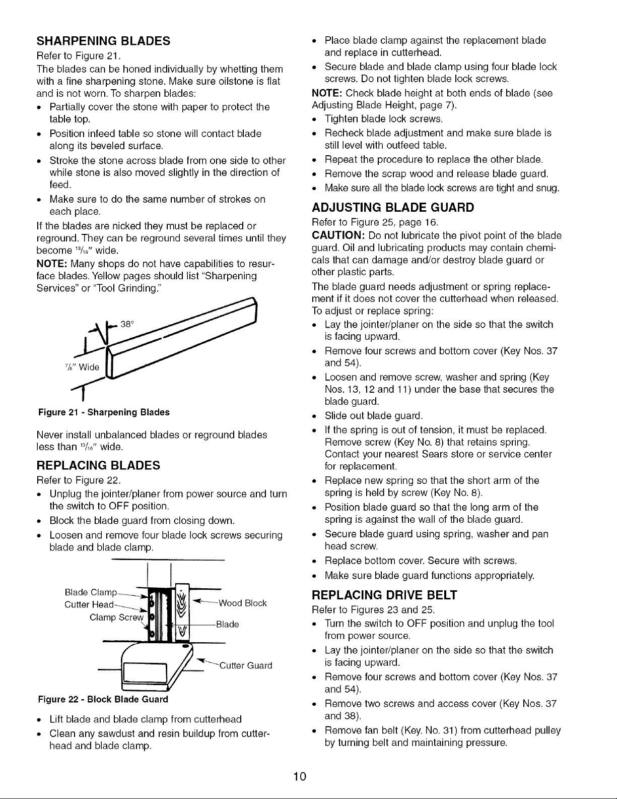
ON-OFF SWITCH
Refer to Figure 15.
The operating positions of the On-Off switch are located
on the front of your jointer/planer.
• Push the switch up to turn jointer/planer on and push
down to turn the unit off.
• The switch has a removable key that allows the unit
to be locked in the OFF position.
To activate locking mechanism:
• Push the switch to OFF position.
• Pull switch key.
To deactivate locking mechanism:
• Insert and press switch key in the slot on switch.
WARNING: Be sure the switch is in OFF position and
the cord is unplugged from the power source before
removing switch key.
Switch Key
Switch_k
Blade Lock
Screw
Blade
Figure 14 - Cutterhead Assembly
Jack Screw
Figure 15 - On-Off Switch
8
FEEDINGWORKPIECE
Refer to Figures 16-18.
Feed rate refers to rate at which wood is passed over
blades. An even feed will produce a uniform service. To
feed workpiece:
• Hold the board firmly down on both tables and
against the fence.
• Keep fingers close together.
• Feed the board at a continuous even rate of speed.
Any hesitation or stopping could cause a "step" to be
cut on the edge of the board.
Figure 16 - FeedingWorkpiece
• As the trailing hand passes over the cutterhead,
remove the leading hand.
• Continue feeding while placing the leading hand
behind the trailing hand until the entire length of the
board is cut.
Figure 17 - Guiding Workpiece
• Feed with the grain whenever possible.
• If the nature of the workpiece is such that it must be
fed against the grain, take very light cuts and feed
slowly.
• When using long workpieces, to avoid injury from slips
or kickbacks and to exert even pressure on the cutter-
head, use extra supports (see Recommended
Accessories, page 17) at both infeed and outfeed ends.
USING HOLD DOWN/PUSH BLOCKS
Refer to Figure 19.
• Always use hold-down/push-blocks when jointing
wood that is narrower than 3", planing wood thinner
than 3".
Figure 19 - Feeding with Push Blocks
• Grasp the hold-down/push-blocks firmly.
• Position the push-blocks flat on top of workpiece and
push the workpiece down against the table.
• Use a hand-over-hand motion to maintain control
over the workpiece at all times.
• When planing workpiece between '/2- 3/4"and nar-
rower than the push-blocks, tilt the push-blocks so
that it clears the cutterhead guard while feeding.
BEVELING AND CHAMFERING
Refer to Figure 20.
• The fence on the jointer/planer is adjustable from
45° inward to 45° outward. Adjust the fence to the
desired angle and tighten fence tilting handle
• Beveling refers to cutting the entire edge of a board
at an angle. Beveling may require several passes
due to the depth of cut needed.
• Chamfering refers to removing only the corner of the
edge of a board. Normally a chamfer is made on one
pass; so a 1/16Hdepth of cut is made.
Bevel Edge
ChamferEd_g_e_
Figure 20 - Beveling and Chamfering
Rotation
Rotation
Figure 18 - Direction of Feed
With the Grain
Against the Grain
WARNING: Turn the switch to OFF position and
unplug jointer/planer from power source before pro-
ceeding to do maintenance work.
CHECKING FOR WORN BLADES
Condition of blades will affect precision of cut. If blade
wear is not observed when checking the blade height,
the quality of cut will indicate the blade condition. Dull
blades will tear rather than sever wood fiber. A raised
grain will occur when dull blades pound on wood where
there is difference in density. A raised ridge will be pro-
duced where the blades have been nicked.
SHARPENING BLADES
Refer to Figure 21.
The blades can be honed individually by whetting them
with a fine sharpening stone. Make sure oilstone is flat
and is not worn. To sharpen blades:
• Partially cover the stone with paper to protect the
table top.
• Position infeed table so stone will contact blade
along its beveled surface.
• Stroke the stone across blade from one side to other
while stone is also moved slightly in the direction of
feed.
• Make sure to do the same number of strokes on
each place.
If the blades are nicked they must be replaced or
reground. They can be reground several times until they
become 13/161'wide.
NOTE: Many shops do not have capabilities to resur-
face blades. Yellow pages should list "Sharpening
Services" or "Tool Grinding."
Figure 21 - Sharpening Blades
Never install unbalanced blades or reground blades
less than '3/16"wide.
REPLACING BLADES
Refer to Figure 22.
• Unplug the jointer/planer from power source and turn
the switch to OFF position.
• Block the blade guard from closing down.
• Loosen and remove four blade lock screws securing
blade and blade clamp.
Blade Clam
Clamp
Figure22 - Block Blade Guard
• Lift blade and blade clamp from cutterhead
• Clean any sawdust and resin buildup from cutter-
head and blade clamp.
• Place blade clamp against the replacement blade
and replace in cutterhead.
• Secure blade and blade clamp using four blade lock
screws. Do not tighten blade lock screws.
NOTE: Check blade height at both ends of blade (see
Adjusting Blade Height, page 7).
• Tighten blade lock screws.
• Recheck blade adjustment and make sure blade is
still level with outfeed table.
• Repeat the procedure to replace the other blade.
• Remove the scrap wood and release blade guard.
• Make sure all the blade lock screws are tight and snug.
ADJUSTING BLADE GUARD
Refer to Figure 25, page 16.
CAUTION: Do not lubricate the pivot point of the blade
guard. Oil and lubricating products may contain chemi-
cals that can damage and/or destroy blade guard or
other plastic parts.
The blade guard needs adjustment or spring replace-
ment if it does not cover the cutterhead when released.
To adjust or replace spring:
• Lay the jointer/planer on the side so that the switch
is facing upward.
• Remove four screws and bottom cover (Key Nos. 37
and 54).
• Loosen and remove screw, washer and spring (Key
Nos. 13, 12 and 11) under the base that secures the
blade guard.
• Slide out blade guard.
• If the spring is out of tension, it must be replaced.
Remove screw (Key No. 8) that retains spring.
Contact your nearest Sears store or service center
for replacement.
• Replace new spring so that the short arm of the
spring is held by screw (Key No. 8).
• Position blade guard so that the long arm of the
spring is against the wall of the blade guard.
• Secure blade guard using spring, washer and pan
head screw.
• Replace bottom cover. Secure with screws.
• Make sure blade guard functions appropriately.
REPLACING DRIVE BELT
Refer to Figures 23 and 25.
• Turn the switch to OFF position and unplug the tool
from power source.
• Lay the jointer/planer on the side so that the switch
is facing upward.
• Remove four screws and bottom cover (Key Nos. 37
and 54).
• Remove two screws and access cover (Key Nos. 37
and 38).
• Remove fan belt (Key. No. 31) from cutterhead pulley
by turning belt and maintaining pressure.
10
 Loading...