


Craftsman 351217680 Owner’s Manual

Operator's Manual
CRRFTSMRNo
BenchTop
JOINTER/PLANER
Model No.
351.217680
CAUTION: Read and follow
all Safety Rules and Operating
Instructions before First Use
of this Product.
Sears, Roebuck and Co., Hoffman Estates, IL 60179 U.S.A.
16303.00 Draft (01/04/00)

Warranty.................................. 2
Safety Rules .............................. 2-3
Unpacking ................................. 3
Assembly ................................. 3
Installation ............................... 4-5
Operation ................................ 5-9
Maintenance ............................ 9-10
Troubleshooting ............................ 11
Parts Illustration and List .................. 13-15
Espahol ............................... 16-26
FULL ONE YEAR WARRANTY
If this product fails due to a defect in material or work-
manship within one year from the date of purchase,
Sears will at its option repair or replace it free of
charge.
Contact your nearest Sears Service Center to arrange
for product repair, or return this product to place of pur-
chase for replacemnt.
If this product is used for commercial or rental purpos-
es, this warranty will apply for 90 days from the date of
purchase.
This warranty gives you specific legal rights, and you
may also have other dghts which vary from state to
state.
Sears, Roebuck and Co., Dept. 817WA, Hoffman
Estates, IL 60179
WARNING: For your own safety, road all of the rules
and precautions before operating tool.
CAUTION: Always follow proper operating procedures
as defined in this manual even if you are familiar with
use of this or similar tools. Remember that being care-
less for even a fraction of a second can result in severe
personal injury.
BE PREPARED FOR JOB
• Wear proper apparel. Do not wear loose clothing,
gloves, neckties, rings, bracelets or other jewelry
which may get caught in moving parts of machine.
• Wear protective hair covering to contain long hair.
• Wear safety shoes with non-slip soles.
• Wear safety glasses complying with United States
ANSi Z87.1. Everyday glasses have only impact
resistant lenses. They are NOT safety glasses.
• Wear face mask or dust mask if operation is dusty.
• Be alert and think clearly. Never operate power tools
when tired, intoxicated or when takin9 medicat'_ons
that cause drowsiness.
PREPARE WORK AREA FOR JOB
• Keep work area clean. Cluttered work areas invite
accidents.
• Do not use power tools in dangerous environments.
• Do not use power tools in damp orwet locations. Do
not expose power tools to rain.
• Work area should be properly lighted.
• Proper electrical receptacle should be available for
tool. Three prong plug should be plugged directly
into propedy grounded, three-prong receptacle.
• Extension cords should have a grounding prong and
the three wires of the extension cord should be of
the correct gauge.
• Keep visitorsat a safe distance from work area.
• Keep children out of workplace. Make workshop child-
proof. Use padlocks, master switches or remove switch
keys to prevent any unintentional use of power tools.
TOOL SHOULD BE MAINTAINED
• Always unplug tool prior to inspection.
• Consult manual for specific maintaining and adjust-
ing procedures.
• Keep tool lubricated and clean for safest operation.
• Remove adjusting tools. Form habit of checking to
see that adjusting tools are removed before switch-
ing machine on.
• Keep all parts in working order. Check to determine
that the guard or other parts will operate propedy
and perform their intended function.
• Check fordamaged parts. Check for alignment of
moving parts, binding, breakage, mounting end any
other condition that may affect a tool's operation.
• A guard or other part that is damaged should be
prepedy repaired or replaced. Do not perform
makeshift repairs. (Use parts list provided to order
replacement parts.)
KNOW HOWTO USE TOOL
• Use right tool forjob. Do not force tool or attachment
to do a job for which it was not designed.
• Disconnect tool when changing blades.
• Avoid accidental start-up. Make sure that the switch
is in the OFF position before plugging in.
• Do not force tool. It will work most efficiently at the
rate for which it was designed.
• Keep hands away from moving pads and cutting
surfaces.
• Never leave tool running unattended. Turn the power
off and do not leave tool until it comes to a complete
stop.
• Do not overreach. Keep proper footing and balance.
• Never stand on tool.Serious injury couldoccur if tool is
tipped or if blade is unintentionally contacted.
• Know your tool. Learn the tool's operation, applica-
tion and specific limitations.
2

• Use recommended accessories (refer to page 15).
Use of improper accessories may cause risk of
injury to persons.
• Handle workpiece correctly. Protect hands from pos-
sible injury.
• Turn machine off if it jams. Blade jams when it digs
too deeply into workpiece. (Motor force keeps it
stuck in the work.)
• Always keep drive, cutterhead and blade guards in
place and in proper operating condition.
• Feed work into blade or cutter against direction of
rotation.
CAUTION: Think safety! Safety is a combination of
operator common sense and alertness at all times
when tool is being used.
WARNING: Do not attempt to operate tool until it is
completely assembled according to the instructions.
Refer to Figure 1.
Check for shipping damage. If damage has occurred, a
claim must be filed with carrier. Check for complete-
ness. Immediately report missing parts to dealer.
The jointer/planer is shipped complete in one carton.
Additional parts which need to be fastened to
jointer/planer should be located and accounted for
before assembling.
A Jointer Bed Assembly
B Fence
C Fence Bracket Assembly
D Push Blocks (2)
Hardware bag includes:
• 6-1.0 x 16mm Socket Head Bolts (2)
• 6mm Lock washer (2)
• '/,-20 x '/2"Socket Head Bolts (4)
• V,'-2O Square Nuts (4)
• 3, 4, 5 L-Wrench
• 8-10 Open Wrench
• Screw Driver
A
Figure I - Unpacking
Refer to Figure 2.
ASSEMBLE FENCE BRACKETTO FENCE
• Lay the fence flat on a level surface so that the sur-
face with the slots is on the top (facing you) and the
beveled fence edge coming toward you.
• Make two vertical marks across the fence width
using a pencil at 103/,6"from each side of the fence.
• Slide two square nuts, one on each slot, from the right
side of fence so that the center of the hex nuts are
aligned with the pencil mark.
• Slide two square nuts from the left side of the fence
up to the pencil mark.
Figure 2 - Assemble Fence Bracket
• Attach the fence bracket to fence using the four '/,"
socket head bolts and square nuts. Make sure the
fence bracket protrusion with two mounting holes is
in the same side as the beveled fence edge.
• Make sure that the two slotted plates on either side
of the fence bracket is parallel to the fence bracket.
• Tighten all bolts.
ASSEMBLE FENCE TO JOINTER
• The fence is attached to the rear of the jointer bed
assembly using the two mounting holes below the
cutterhead.
• Position the fence assembly against the rear of the
jointer so that the two mounting holes on the protru-
sion plate on the fence bracket are aligned with the
mounting holes on the rear of the jointer.
• Attach fence assembly to jointer using two 6mm
socket head bolts and lock washers provided.
• Loosen the handle on the rear of the fence bracket.
• The fence assembly can be slid forward now.
• Slide fence assembly forward so that the fence is
over the jointer tables. At this position the edge of
the blade guard will rest against the fence, and the
entire width of the cutterhead is covered.
• Place a combination square against face of fence
and table surface. The fence and table must be at
90" to each other. If not, loosen the tilt handle and
bring face of fence square to table and tighten tilt
handle.
• Make sure the pointer on the side of fence bracket
reads 0°.
• Tighten all bolts and handles.
3
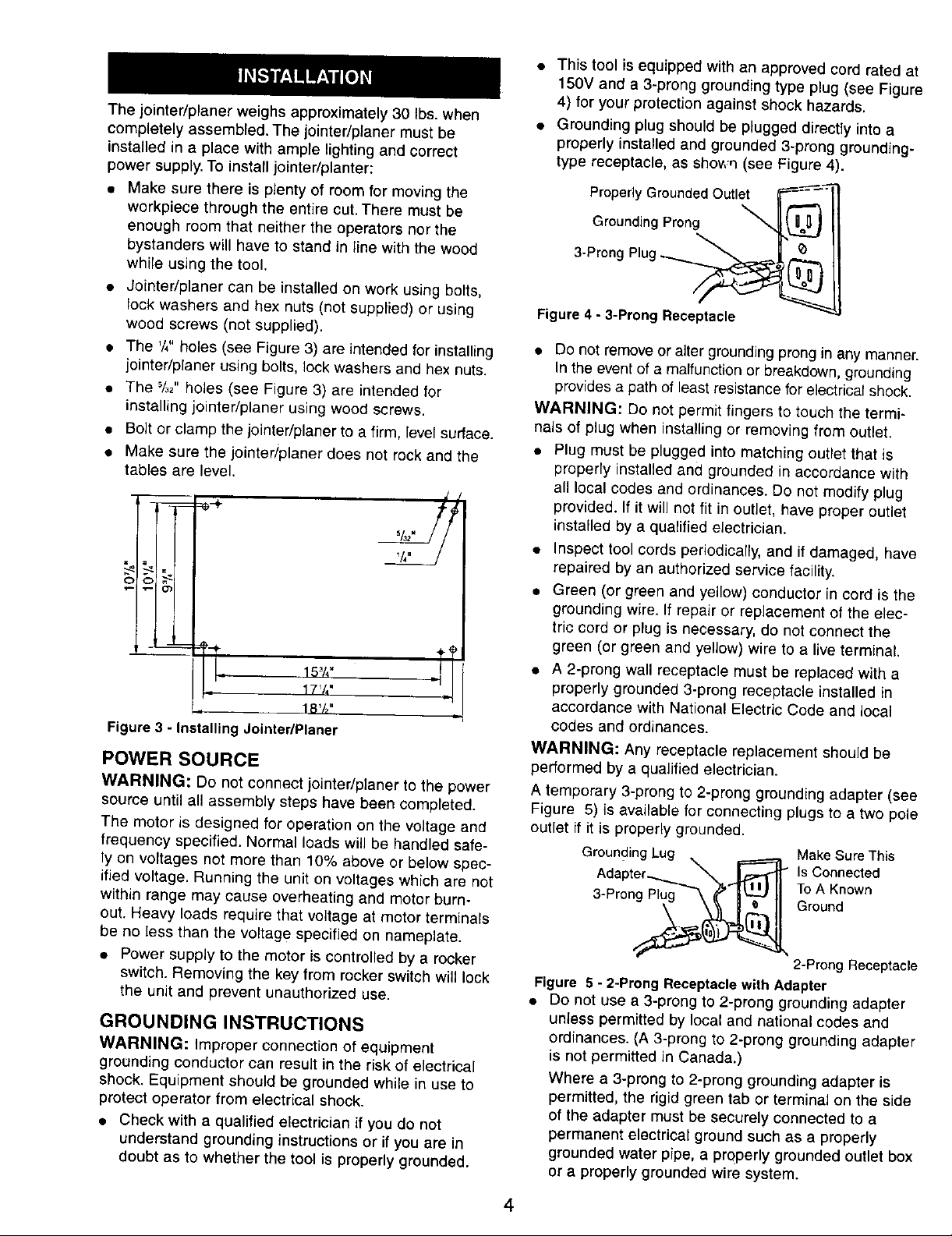
The jointer/planer weighs approximately 30 Ibs. when
completely assembled. The jointer/planer must be
installed in a place with ample lighting and correct
power supply. To install jointer/planter:
• Make sure there is plenty of room for moving the
workpiece through the entire cut. There must be
enough room that neither the operators nor the
bystanders will have to stand in line with the wood
while using the tool.
• Jointer/planer can be installed on work using bolts,
lock washers and hex nuts (not supplied) or using
wood screws (not supplied).
• The '/," holes {see Figure 3) are intended for installing
jointer/planer using bolts, lock washers and hex nuts.
• The %2"holes (see Figure 3) are intended for
installing jointer/planer using wood screws.
• Bolt or clamp the jointer/planer to a firm, level surface.
• Make sure the jointedplaner does not rock and the
tables are level.
17V,"
18'/_"
Figure 3 - Installing JointedPlaner
POWER SOURCE
WARNING: Do not connect jointedplaner to the power
source until all assembly steps have been completed.
The motor is designed for operation on the voltage and
frequency specified. Normal loads will be handled safe-
ly on voltages not more than 10% above or below spec-
ified voltage. Running the unit on voltages which are not
within range may cause overheating and motor burn-
out. Heavy loads require that voltage at motor terminals
be no less than the voltag e specified on nameplate.
• Power supply to the motor is controlled by a rocker
switch. Removing the key from rocker switch will lock
the unit and prevent unauthorized use.
GROUNDING INSTRUCTIONS
WARNING: Improper connection of equipment
grounding conductor can result in the risk of electrical
shock. Equipment should be grounded while in use to
protect operator from electrical shock.
• Check with a qualified electrician if you do not
understand grounding instructions or if you are in
doubt as to whether the tool is properly grounded.
• This tool is equipped with an approved cord rated at
150V and a 3-prong grounding type plug (see Figure
4) for your protection against shock hazards.
• Grounding plug should be plugged directly into a
properly installed and grounded 3-prong grounding-
type receptacle, as shov,'q (see Figure 4).
Properly Grounded Outlet i_--=-'--_
3-Prong P!ug :_=,,'a_/"_
Figure4 - 3-Prong Receptacle
• Do not remove or alter grounding prong in any manner.
In the event of a malfunction or breakdown, grounding
provides a path of least resistance for electrical shock.
WARNING: Do not permit fingers to touch the termi-
nals of plug when installing or removing from outlet.
• Plug must be plugged into matching outlet that is
properly installed and grounded inaccordance with
all local codes and ordinances. Do not modify plug
provided. If it will not fit in outlet, have proper outlet
installed by a qualified electrician.
• Inspect tool cords periodically, and it damaged, have
repaired by an authorized service facility.
• Green (or green and yellow) conductor in cord is the
grounding wire. If repair or replacement of the elec-
tric cord or plug is necessary, do not connect the
green (or green and yellow) wire to a live terminal.
• A 2-prong wall receptacle must be replaced with a
properly grounded 3-prong receptacle installed in
accordance with National Electric Code and local
codes and ordinances.
WARNING: Any receptacle replacement should be
performed by a qualified electrician.
A temporary 3-prong to 2-prong grounding adapter (see
Figure 5) is available for connecting plugs to a two pole
outlet if it is properly grounded.
Grounding Lug _ i========_
Adapter_ "X%_ I
3 Pron__
Make Sure This
Is Connected
To A Known
Ground
2-Prong Receptacle
Figure 5 - 2-Prong Receptacle with Adapter
• Do not use a 3-prong to 2-prong grounding adapter
unless permitted by local and national codes and
ordinances. (A 3-prong to 2-prong grounding adapter
is not permitted in Canada.)
Where a 3-prong to 2-prong grounding adapter is
permitted, the rigidgreen tab or terminal on the side
of the adapter must be securely connected to a
permanent electrical ground such as a properly
grounded water pipe, a properly grounded outlet box
or a properly grounded wire system.
4

• Many cover plate screws, water pipes and outlet
boxes are not properly grounded. To ensure proper
ground, grounding means must be tested by a quali-
fied electrician.
EXTENSION CORDS
• The use of any extension cord will cause some drop
in voltage and loss of power.
• Wires of the extension cord must be of sufficient size
to carry the current and maintain adequate voltage.
• Use the table to determine the minimum wire size
(A.W.G.) extension cord.
• Use only 3-wire extension cords having 3-preng
grounding type plugs and 3-pole receptacles which
accept the tool plug.
• If the extension cord is worn, cut or damaged in any
way, replace it immediately.
EXTENSION CORD LENGTH
Wire Size A.W.G.
Up to 50 ft................................ 16
50-100 ft.................................. 14
NOTE: Using extension cords over 100 ft. long is not
recommended.
MOTOR
Jointer/planer is supplied with a 1'/2HP (max devel-
oped) motor.
The 120 Volt AC universal motor has the following
specifications:
Horsepower (Maximum Developed) ............. 1_/2
Voltage ..................... "............ 120
Amps ................................... 10
Hertz .................................... 60
Phase ................................ Single
RPM .................................. 8000
ELECTRICAL CONNECTIONS
WARNING: Make sure unit is turned oft and discon-
nected from power source before inspecting any wiring.
The unit is wired as illustrated in the wiring schematic
(see Figure 6).
Switch
White'L_ White
i
Figure 6 - Wiring Schematic
The motor is assembled with an approved three con-
ductor cord to be used on 120 volts as indicated. The
power supply to the motor is controlled by a double
- pole locking rocker switch.
• Remove the key to prevent unauthorized use.
The power lines are inserted directly onto the switch.
The green ground line must remain securely fastened
to the frame to properly protect against electrical shock.
DESCRIPTION
Craftsman 6'/8"jointer/planeris used to surface the faces
and edges of boards, produce a flat surface on warped
boards and shape bevels, chamfers and tapers. The joint-
er/planer features cast aluminum infeed and outfeed
tables, lightweight plastic body with smooth work sur-
faces and leadscrews for precise table height adjustment.
Balanced guide fence tilts 45" (inward) and 45" (outward).
Tool comes with locking rocker switch with removable key
and push blocks. Jointer/planer easily handles rough-cut
lumber, planes hard and soft woods up to 6'/6"wide using
a two blade cutterhead, and takes cuts up to '/8"
OPERATION SAFETY RULES
Jointing is a surfacing operation in which a small
amount of wood is removed from the edges and faces of
boards to get smooth, straight and even surfaces such
that the two edges that run across the planing blocks
would fit together perfectly, forming a seamless joint.
Planing refers to the sizing of lumber to a desired thick-
ness while creating a level surface parallel to the oppo-
site size of the board. Depth of cut is the term used to
indicate how deep the blades will cut into the workpiece.
WARNING: Operation of any power tool can result in
foreign objects being thrown into eyes which can result
in severe eye damage. Always wear safety goggles
complying with United States ANSI Z87.1 (shown on
package) before commencing power tool operation.
WARNING: For your own safety, read all of the
instructions and safety precautions before operating
tool.
• Know general power tool safety. Make sure all pre-
cautions are understood (see pages 2, 3, 5 and 6).
• Whenever adjusting or replacing any parts on
jointer/planer, turn switch oft and remove plug from
power source.
• Make sure all guards are properly attached and
securely fastened.
• Make sure all moving parts are free from interference.
• Always wear eye protection or face shield.
• Make sure blades are aligned and properly attached
to cutterhead.
• Do not plug in jointer/planer unless switch is in "off"
position. After turning switch on, allow jointer/planer
to come to full speed before operating.
• Keep hands clear of all moving parts.
• Do not force cut. Slowing or stalling will overheat
motor,
5