

Craftsman 351217590 Owner’s Manual

Operator's Manual
13"
PLANER WITH DUST COLLECTION
Model No.
351.21 7590
CAUTION: Read and follow
all Safety Rules and Operating
Instructions before First Use
of this Product.
Sears, Roebuck and Co., Hoffman Estates, IL 60179 U.S.A.
www.sears.com/craftsman
24976.01 Draft (03/27/07)

Warranty ......................................... 2
Safety Rules .................................... 2-3
Unpacking ....................................... 3
Assembly ...................................... 3-4
Installation ....................................... 5
Operation ...................................... 6-9
Maintenance ................................... 9-12
Troubleshooting .................................. 13
Parts Illustrations and Lists....................... 14-17
EspaSol ...................................... 18-31
ONE-YEAR FULL WARRANTY ON
CRAFTSMAN PROFESSIONAL TOOL
If this Craftsman tool fails due to a defect in material or
workmanship within one year from the date of purchase, call
1-800-4-MY-HOME® TO ARRANGE FOR FREE REPAIR
(or replacement if repair proves impossible). This warranty
does not include expendable parts, such as lamps, batteries,
bits or blades.
If this tool is ever used for commercial or rental purposes, this
warranty will apply for only 90 days from the date of purchase.
This warranty gives you specific legal rights and you may also
have other rights which vary from state to state.
Sears, Roebuck and Co., Hoffman Estates, IL 60179
WARNING: For your own safety, read all of the rules and
precautions before operating tool.
WARNING: Some dust created by power-sanding, sawing,
grinding, drilling and other construction activities contains
chemicals known to cause cancer, birth defects or other
reproductive harm.
Some examples of these chemicals are:
° Lead from lead-based paints.
° Crystalline silica from bricks and cement and other
masonry products.
° Arsenic and chromium from chemically-treated lumber.
Your risk from these exposures vary, depending on how often
you do this type of work. To reduce your exposure to these
chemicals: work in a well ventilated area and work with approved
safety equipment. Always wear OSHA/NIOSH approved,
properly fitting face mask or respirator when using such tools.
CAUTION: Always follow proper operating procedures as
defined in this manual even if you are familiar with use of
this or similar tools. Remember that being careless for even
a fraction of a second can result in severe personal injury.
BE PREPARED FOR JOB
* Wear proper apparel. Do not wear loose clothing, gloves,
neckties, rings, bracelets or other jewelry which may get
caught in moving parts of machine.
* Wear protective hair covering to contain long hair.
* Wear safety shoes with non-slip soles.
* Wear safety glasses complying with United States
ANSI Z87.1. Everyday glasses have only impact
resistant lenses. They are NOT safety glasses.
* Wear face mask or dust mask if operation is dusty.
* Be alert and think clearly. Never operate power tools
when tired, intoxicated or when taking medications
that cause drowsiness.
PREPARE WORK AREA FOR JOB
* Keep work area clean. Cluttered work areas invite
accidents.
* Do not use power tools in dangerous environments.
* Do not use power tools in damp or wet locations. Do
not expose power tools to rain.
* Work area should be properly lighted.
* Proper electrical receptacle should be available for tool.
Three-prong plug should be plugged directly into properly
grounded, three-prong receptacle.
* Extension cords should have a grounding prong and the
three wires of the extension cord should be of the correct
gauge.
* Keep visitors at a safe distance from work area.
* Keep children out of workplace. Make workshop childproof.
Use padlocks, master switches or remove switch keys to
prevent any unintentional use of power tools.
TOOL SHOULD BE MAINTAINED
* Always unplug tool prior to inspection.
* Consult manual for specific maintaining and adjusting
procedures.
* Keep tool lubricated and clean for safest operation.
* Remove adjusting tools. Form habit of checking to see that
adjusting tools are removed before switching machine on.
* Keep all parts in working order. Check to determine that
the guard or other parts will operate properly and perform
their intended function.
* Check for damaged parts. Check for alignment of moving
parts, binding, breakage, mounting and any other condi-
tion that may affect a tool's operation.
* A guard or other part that is damaged should be properly
repaired or replaced. Do not perform makeshift repairs.
(Use parts list provided to order repair parts.)
KNOW HOW TO USE TOOL
* Use right tool for job. Do not force tool or attachment to
do a job for which it was not designed.
* Disconnect tool when changing blades.
* Avoid accidental start-up. Make sure that the switch is in
the OFF position before plugging in.
* Do not force tool. It will work most efficiently at the rate
for which it was designed.
* Keep hands away from moving parts and cutting surfaces.
* Never leave tool running unattended. Turn the power off
and do not leave tool until it comes to a complete stop.
* Do not overreach. Keep proper footing and balance.
* Never stand on tool. Serious injury could occur if tool is
tipped or if blade is unintentionally contacted.
* Know your tool. Learn the tool's operation, application
and specific limitations.
* Use recommended accessories (refer to page 17). Use of
improper accessories may cause risk of injury to persons.
* Handle workpiece correctly. Protect hands from possible
injury.
© Sears, Roebuck and Co. 2
• Turn machine off if it jams. Blade jams when it digs too
deeply into workpiece. (Motor force keeps it stuck in
the work.)
• Always keep drive, cutterhead and blade guards in place
and in proper operating condition.
• Feed work into blade against direction of rotation.
CAUTION: Think safety! Safety is a combination of operator
common sense and alertness at all times when tool is
being used.
WARNING: Do not attempt to operate tool until it is
completely assembled according to the instructions.
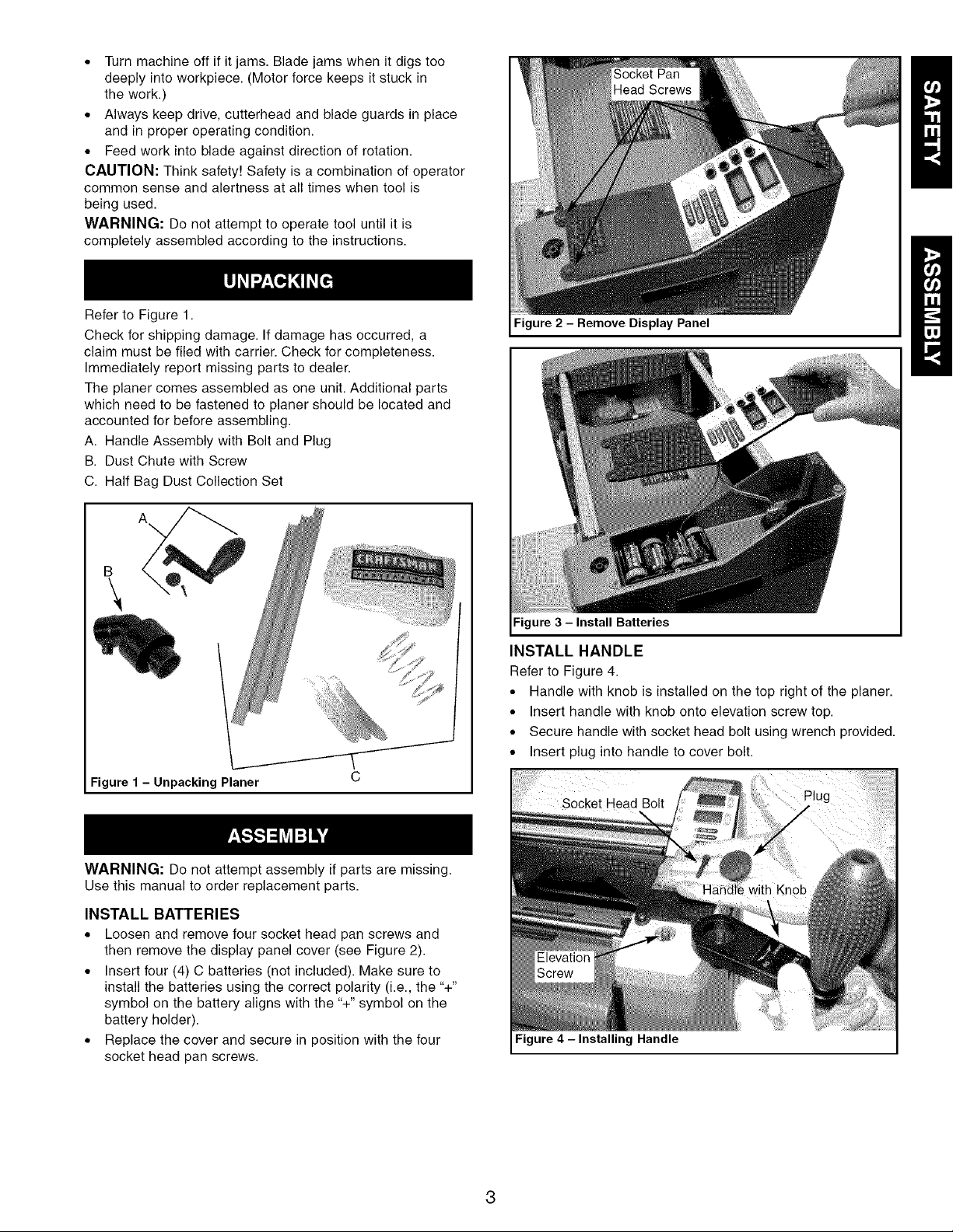
Refer to Figure 1.
Check for shipping damage. If damage has occurred, a
claim must be filed with carrier. Check for completeness.
Immediately report missing parts to dealer.
The planer comes assembled as one unit. Additional parts
which need to be fastened to planer should be located and
accounted for before assembling.
A. Handle Assembly with Bolt and Plug
B. Dust Chute with Screw
C. Half Bag Dust Collection Set
A
\
B
\
Figure 1 - Unpacking Planer
C
Figure 2 - Remove Display Panel
Figure 3 - Install Batteries
INSTALL HANDLE
Refer to Figure 4.
° Handle with knob is installed on the top right of the planer.
° Insert handle with knob onto elevation screw top.
° Secure handle with socket head bolt using wrench provided.
° Insert plug into handle to cover bolt.
I
WARNING: Do not attempt assembly if parts are missing.
Use this manual to order replacement parts.
INSTALL BATTERIES
* Loosen and remove four socket head pan screws and
then remove the display panel cover (see Figure 2).
* Insert four (4) C batteries (not included). Make sure to
install the batteries using the correct polarity (i.e., the "+"
symbol on the battery aligns with the "+" symbol on the
battery holder).
* Replace the cover and secure in position with the four
socket head pan screws.
Figure 4 - Installing Handle

INSTALL DUST CHUTE
Refer to Figure 5.
• Slide dust chute over fan housing. Secure in position with
screw.
° Attach the Half Bag Dust Collection Set (included) only
after mounting planer to stand or workbench.
° A 4" diameter dust collection hose (not included) can be
also attached to the outer port.
Figure 5 - Installing Dust Chute
MOUNT PLANER TO STAND
Refer to Figure 6.
CAUTION: Planer weighs approximately 100 Ibs. Two people
may be required to lift planer.
° Planer is designed to be portable so it can be moved to
job site, but should be mounted to a stand or workbench
for stability.
• Make sure stand is located on a firm, level surface in a
place with ample lighting and correct power supply.
° Make sure there is plenty of room for moving the work-
piece through the entire cut. There must be enough room
that neither the operators or bystanders will have to stand
in line with the wood while using the tool.
• The base of the planer has four mounting holes, two in
front (shown in Figure 6) and two in the rear.
J
3/8_f
Dia.
15"
25W'
Figure7 - Base and Mounting Dimensions
INSTALL THE HALF BAG DUST COLLECTION SET
Refer to Figure 8.
The Craftsman Half Bag Dust Collection Set is designed
to provide dust collection for woodworking tools with a 2_/2''
diameter dust exhaust port. The filter bag attaches to a
30-gallon trash can or a 30-gallon x 1.3 mil plastic trash
bag for easy, convenient sawdust disposal (trash can and
plastic trash bag not included).
• Mount planer to stand before installing Dust Collection Set.
To use dust collection set with a trash can:
• Place spring inside filter bag arm.
• Slide arm with spring over dust chute.
• Place band of the bag over rim of trash can and secure
bag by tightening strap.
To use dust collection set with a trash bag:
• Place spring inside filter bag arm.
• Slide arm with spring over dust chute.
• Assemble bag support. Slide connectors into channels of
support segments.
• Slide plastic trash bag inside and over bag support. Let
bag overlap 3-4".
• Place band of the filter bag over and into the channel of
the bag support.
• Secure in position by tightening strap.
T
11%"
Figure 6 - Planer Mounting Holes (Front)
° Mount planer to workbench or tool stand (see Recom-
mended Accessories, page 17) using bolts, flat washers
and hex nuts (not supplied).
° Figure 7 shows the base dimensions and mounting hole
dimensions of the planer.
Spring _.,_ Dust Chute
Filter _ _¢_" Support
Connector
Band "_ P 5_ j Support
Trash _ J
Can f
Figure 8 - Half Bag Dust Collection Set
4
Segments

POWER SOURCE
WARNING: Do not connect planer to the power source
until all assembly steps have been completed.
The motor is designed for operation on the voltage and
frequency specified. Normal loads will be handled safely on
voltages not more than 10% above or below specified voltage.
Running the unit on voltages which are not within range may
cause overheating and motor burn out. Heavy loads require
that voltage at motor terminals be no less than the voltage
specified on nameplate.
° Power supply to the motor is controlled by a switch with
key. Removing the key from switch will lock the unit and
prevent unauthorized use.
GROUNDING INSTRUCTIONS
WARNING: Improper connection of equipment grounding
conductor can result in the risk of electrical shock. Equipment
must be grounded while in use to protect operator from
electrical shock.
° Check with a qualified electrician if you do not understand
grounding instructions or if you are in doubt as to whether
the tool is properly grounded.
° This tool is equipped with an approved cord rated at 150V
and a 3-prong grounding type plug (see Figure 9) for
your protection against shock hazards.
° Grounding plug should be plugged directly into a properly
installed and grounded 3-prong grounding-type receptacle,
as shown (see Figure 9).
Properly Grounded Outlet..,.,_'_i 1
Grounding Prong.
3-Prong Plug _.1"_" _
Figure 9 - 3-Prong Receptacle
• Do not remove or alter grounding prong in any manner.
In the event of a malfunction or breakdown, grounding
provides a path of least resistance for electrical shock.
WARNING: Do not permit fingers to touch the terminals of
plug when inserting or removing from outlet.
• Plug must be plugged into matching outlet that is properly
installed and grounded in accordance with all local codes
and ordinances. Do not modify plug provided. If it will not fit
in outlet, have proper outlet installed by a qualified electrician.
• Inspect tool cords periodically, and if damaged, have
repaired by an authorized service facility.
• Green (or green and yellow) conductor in cord is the
grounding wire. If repair or replacement of the electric
cord or plug is necessary, do not connect the green
(or green and yellow) wire to a live terminal.
• A 2-prong wall receptacle must be replaced with a properly
grounded 3-prong receptacle installed in accordance with
National Electric Code and local codes and ordinances.
WARNING: Any receptacle replacement should be per-
formed by a qualified electrician.
A temporary 3-prong to 2-prong grounding adapter (see
Figure 10) is available for connecting plugs to a two pole
outlet if it is properly grounded.
Grounding Lug _
Adapter II
3-Prong P_. _
Figure 10 - 2-Prong Receptacle with Adapter
Do not use a 3-prong to 2-prong grounding adapter unless
permitted by local and national codes and ordinances.
(A 3-prong to 2-prong grounding adapter is not permitted
in Canada.)
Where a 3-prong to 2-prong grounding adapter is
permitted, the rigid green tab or terminal on the side of
the adapter must be securely connected to a permanent
electrical ground such as a properly grounded water pipe,
a properly grounded outlet box or a properly grounded
wire system.
Many cover plate screws, water pipes and outlet boxes
are not properly grounded. To ensure proper ground,
grounding means must be tested by a qualified electrician.
EXTENSION CORDS
• The use of any extension cord will cause some drop in
voltage and loss of power.
• Wires of the extension cord must be of sufficient size
to carry the current and maintain adequate voltage.
° The minimum extension cord wire size is A.W.G. 12.
Do not use extension cords over 25 feet long.
• Use only 3-wire extension cords having 3-prong grounding
type plugs and 3-pole receptacles which accept the
tool plug.
• If the extension cord is worn, cut or damaged in any way,
replace it immediately.
Planer is supplied with a 15 Amp motor installed.
The 120 Volt AC universal motor has the following
specifications:
Voltage ........................................ 120
Amperes ........................................ 15
Hertz .......................................... 60
Phase ....................................... Single
Cutterhead RPM ............................... 8000
ELECTRICAL CONNECTIONS
WARNING: Make sure unit is turned off and disconnected
from power source before inspecting any wiring.
The motor is assembled with an approved three conductor
cord to be used on 120 volts. The power supply to the motor
is controlled by a double pole locking switch.
The power lines are connected directly to the switch. The
green ground line must remain securely fastened to the
frame to properly protect against electrical shock.
A manual reset overload protector is installed in line with
the power supply to the motor. If the planer is overloaded,
the protector will break the circuit.
Make Sure This
Is Connected
To A Known
Ground
2-Prong Receptacle

Craftsman13"planerfinishesrough-cutlumbertosizeand
planessoftandhardwoodsupto6"thickand13"wide.Wood
feedsintothree-bladecutterheadbyrubberinfeed/outfeed
rollers.Sturdybaseconstructionandfour-postdesignpermits
smoothfeedingandvirtuallysnipelessplaning.Planercomes
withenclosed,universalballbearing,15Ampmotorwith
overloadprotection.MotorhasON/OFFswitchwithremovable
keytopreventaccidentalstart-up.Unitfeaturesdigitaldisplay,
two-speedfeedsystem,depth-of-cutgaugeforconvenient
setup,workpiecethicknesspre-setgaugewith6settingsfor
consistentsetup,easyhands-freereplacementofbladesfor
safetyandminimizeddowntime,built-industcollector,topmount-
edrollersforworkpiecereturn,built-incarryinghandles,cord
wrapforportabilityandfoldinginfeed/outfeedtableswithrollers
forsmoothoperation.Planertakescutsupto3/32"perpassat
either11or22feetperminute.Inchheightscalehasgraduations
in_/_"increments,andmetricheightscalehasgraduationsin
lmmincrements.(RequiresfourCbatteries,notincluded.)
SPECIFICATIONS
TableSize................................ 13x14W'
ExtensionTableSize........................ 13x12W'
BaseSize................................. 25_/2x15"
WorkpieceWidth(max.)........................... 13"
WorkpieceThickness(max.)........................ 6"
MaximumDepthofCut........................... 3/32"
CutsPerMinute.............................. 24,000
FeedRate............................... 11/22FPM
OverallDimensions................ 21"Hx27"Wx39"D
Weight..................................... 106Ibs
OPERATIONSAFETYRULES
WARNING: For your own safety, read all of the instructions
and precautions before operating tool.
WARNING: Operation of any power tool can result in foreign
objects being thrown into eyes which can result in severe eye
damage. Always wear safety goggles complying with United
States ANSI Z87.1 (shown on package) before commencing
power tool operation.
CAUTION: Always observe the following safety precautions:
• Know general power tool safety. Make sure all precautions
are understood (see pages 2 and 6).
• Whenever adjusting or replacing any parts on planer, turn
switch OFF and remove plug from power source.
° Make sure all guards are properly attached and securely
fastened.
• Make sure all moving parts are free from interference.
• Always wear eye protection or face shield.
° Make sure blades are aligned and properly attached to
cutterhead.
° Do not plug in planer unless switch is in OFF position.
After turning switch on, allow planer to come to full
speed before operating.
° Keep hands clear of all moving parts.
° Do not force cut. Slowing or stalling will overheat motor.
Allow automatic feed to function properly.
* Use quality lumber. Blades last longer and cuts are
smoother with good quality wood.
• Do not plane material shorter than 15", narrower than 3/,,,
wider than 13" or thinner than W'.
• Never make planing cut deeper than 3/32".
• Maintain the proper relationships of infeed and outfeed
table surfaces and cutterhead blade path.
• Do not back the work toward the infeed table.
• Take precautions against kickback. Do not permit anyone
to stand or cross in line of cutterhead's rotation. Kickback
or thrown debris will travel in this direction.
• Turn switch off and disconnect power whenever planer is
not in use.
• Replace blades as they become damaged or dull.
• Keep planer maintained. Follow maintenance instructions
(see pages 9-12).
OPERATING CONTROLS
ON/OFF SWITCH
Refer to Figure 11.
The ON/OFF switch is located on the front of the planer
motor. To turn the planer ON, lift switch cover and move the
switch to the up position. To turn the planer OFF, move the
switch to the down position by pushing down on the switch
cover.
CIRCUIT BREAKER
Refer to Figure 11.
The planer is equipped with a motor protection device-circuit
breaker. The breaker will automatically shut the planer off
when excessive current is consumed.
If the breaker is tripped, turn the planer off and reset the
circuit by pressing the button.
CAUTION: Be sure to turn the planer off prior to resetting
the circuit breaker to avoid unintentional start-up of the planer.
ON/OFF Switch
Figure 11 - ON/OFF Switch and Circuit Breaker
NOTE: Switch cover has been removed for illustration.
SWITCH LOCK
Refer to Figure 12, page 7.
The planer can be locked from unauthorized use by locking
the switch. To lock the switch:
* Turn the switch to OFF position and disconnect planer
from power source.
. Pull the key out. The switch cannot be turned on with the
key removed.
NOTE: Should the key be removed from the switch at the ON
position, the switch can be turned off but cannot be turned on.
. To replace key, slide key into the slot on switch until it snaps.
6

Figure 12 - Removing Locking Key
RAISING AND LOWERING ROLLERCASE
The rollercase contains the motor, cutterhead and dust
collection impeller. The depth-of-cut is controlled by raising
or lowering the rollercase.
To raise or lower the rollercase, rotate handle with knob.
One complete rotation of handle will raise or lower rollercase
by _/_" (see Figure 13).
A rotational direction label with depth indicator is located
under the handle.
Figure 14 - Feed Rate Adjustment, Depth of Cut and
Thickness Scale
WORKPIECE THICKNESS PRESET GAUGE
Refer to Figure 15.
A six position workpiece thickness pre-set control knob is
mounted on the right side of the planer. This feature allows
quick production of identically sized workpieces. Six settings
are provided: %", W', _/2",3/4%1" and 1W'. See "Maintenance"
section to calibrate thickness preset gauge.
Figure 13 - Raising or Loweringthe Rollercase.
Counterclockwise Down/Clockwise Up
FEED RATE ADJUSTMENT
Refer to Figure 14.
• The planer has a 2-speed gearbox that feeds the work-
piece at 22 feet per minute (standard planing) and at
11 feet per minute (finish planing).
Finish planing a workpiece results in a better surface finish
than that obtained by planing at the higher speed.
• The knob for adjusting the feed rate is located on the left
side of the top of the rollercase.
NOTE: Only change feed rate while the machine is running.
DEPTH-OF-CUT GAUGE AND SCALE
Refer to Figure 14.
A depth-of-cut gauge is attached to the front of the rollercase.
The pointer on the depth-of-cut gauge accurately displays the
depth-of-cut per pass when workpiece is positioned below the
gauge. Cranking the handle moves the rollercase down and
the pointer shows depth-of-cut up to 3/32".
Recommended Maximum Depth-Of-Cut:
Hard/Softwood up to 6" wide: ...................... 3/32"
Hard/Softwood 6" to 13" wide: ..................... _/,_"
The Thickness scale with pointer allows easy adjustment of
roller case height. This scale indicates the finished size of the
workpiece in inches and millimeters. The side pointer can
be adjusted by loosening the pointer screws, re-positioning
pointer and retightening pointer screws.
Thickness Preset Gauge
Figure 15 -Thickness Preset Gauge
Example: Plane a 2" thick workpiece down to 1'/4".
° Raise or lower rollercase until it is just above the
workpiece.
° Position the workpiece on the planer table below the
rollercase.
° Rotate knob until 1W' is indicated.
° The planer is now set to stop the rollercase when the
workpiece thickness reaches 1W'.
NOTE: To reset for a different depth stop, raise the rollercase
by about 2 rotations. Turn knob to desired setup.
DIGITAL DISPLAY PANEL
Refer to Figure 16, page 8.
° The digital display panel consists of two LCD displays
and four control buttons.
° Display "A" shows the absolute height of the rollercase
over the table, which is also the finished workpiece
thickness.
° Display "B" shows the depth of cut on the workpiece.
° Button 'A' is used to calibrate display 'A'.
° Button 'B' is used to reset display 'B' to zero (0).
° Button 'C' toggles both displays A and B between inches
and millimeters.
° Button 'D' turns power On and Off to display 'A' and 'B'.

* Thedisplaywillautomaticallyturnitselfoffafterseveral
minutesofnon-use.
NOTE:Thedigitaldisplaydoesnotregisterheightwhendis-
playisoff.Ifthecutterheadismovedwhendisplayisoff,itwill
notdisplaycorrectheightanddisplaymustberecalibrated.
Figure 16 - Digital Display Panel
CALIBRATING AND USINGTHE DIGITAL DISPLAY
To calibrate the display "A":
• Set the preset depth control knob at 1" (see Figure 15,
page 7).
• Plane a piece of scrap wood to 1". Check wood thickness
with caliper to ensure wood thickness, preset stop and dig-
ital display match. If the wood thickness and preset stop
do not correspond, calibrate the preset stop prior to cali-
brating the digital display. See "Maintenance", page 12.
• Remove button 'A', and using a punch or other suitable
object, insert into the button hole and press. The display
A will read 1.0000" or 25.4 mm. (see Figure 17).
To use depth of cut display "B":
• Feed workpiece through planer, taking a shallow cut.
Depress button 'B', which will set display B to zero (0).
• Lower rollercase until desired depth of cut is shown on
display "B".
• Feed workpiece and repeat.
° Twisted or severely warped boards can jam planer. Rip
lumber in half to reduce magnitude of warp.
° Work should be fed into planer in same direction as the
grain of the wood. Sometimes grain will change directions
in middle of board. In such cases, if possible, cut board
in middle before planing so grain direction is correct.
CAUTION: Do not plane board which is less than 15" long;
force of cut could split board and cause kickback.
PLANING
WARNING: Always turn the planer off and disconnect it from
the power source whenever blade cover is removed. Never
operate planer without the blade cover properly secured.
The planer is supplied with planing blades mounted in the
cutterhead and the infeed and outfeed rollers adjusted to the
correct height. The planer is capable of working at two differ-
ent feed rates. Feed rate refers to rate at which lumber travels
through planer. Planing can be done at 22 FPM (standard
planing) or at 11 FPM for an improved surface finish (see
Feed Rate Adjustment).
° Position rollercase to produce the depth of cut desired.
° Operator is responsible for aligning work so it will feed
properly.
° Lift edge to infeed side of the table by grasping edges
of board at approximately middle of length.
° Boards longer than 24" should have additional support
from free standing material stands.
° Position the workpiece with the face to be planed on top.
° Turn the planer on.
° Rest board end on infeed table and direct board into planer.
° Gently slide the workpiece into the infeed side of the planer
until the infeed roller begins to advance the workpiece.
° Let go of the workpiece and allow automatic feed to
advance the workpiece.
° Do not push or pull on workpiece.
° Move to the rear and receive planed lumber by grasping
it in same manner as it was fed.
CAUTION: Do not stand directly in line with front or rear
of planer.
° Do not grasp any portion of board which has not gone
past out-feed roller.
° Repeat this operation on all boards which need to be
same thickness.
Planer has return rollers on top so assistant can pass work
back to operator (see Figure 18).
Figure 17 - Calibrating the LCD Display
PREPARE WORK
* Thickness planer works best when lumber has at least
one flat surface.
* Use surface planer or jointer to create a flat surface.
Figure 18 -Workpiece on the Return Rollers
8

NOTE: Assistant must follow same precautions as operator.
• Surface that the planer produces is smoother if shallower
depth of cut is used.
DEPTH OF CUT
Thickness planing refers to the sizing of lumber to a
desired thickness while creating a level surface parallel to
the opposite side of the board. Board thickness which the
planer will produce is indicated by the scale and LCD display.
Preset the planer to the desired thickness of finished work-
piece using knob. See "Workpiece Thickness Pre-set Gauge",
page 7.
Depth-of-cut is adjusted by raising or lowering the rollercase
using handle.
• Quality of thickness planing depends on the operator's
judgement about the depth of cut.
• Depth of cut depends on the width, hardness, dampness,
grain direction and grain structure of the wood.
• Maximum thickness of wood which can be removed in one
pass is 3/32"for planing operations on workpiece up to 6"
wide. Workpiece must be positioned away from the center
line of the table to cut 3/32"due to limit tab in the center
of the rollercase.
• Maximum thickness of wood which can be removed in one
pass is _/_6"for planing operations on workpiece from 6" up
to 13" wide.
• For optimum planing performance, the depth of cut should
be less than V_6".
• Board should be planed with shallow cuts until the work
has a level side. Once a level surface has been created,
flip the lumber and create parallel sides.
• Plane alternate sides until the desired thickness is
obtained. When half of total depth of cut is taken from
each side, the board will have a uniform moisture
content and additional drying will not cause it to warp.
• Depth of cut should be shallower when work is wider.
• When planing hardwood, take light cuts or plane the wood
in thin widths.
• Make a test cut with a test piece and verify the thickness
produced.
• Check accuracy of test cut prior to working on finished
product.
AVOID DAMAGE TO BLADES
• Thickness planer is a precision woodworking machine
and should be used on quality lumber only.
• Do not plane dirty boards; dirt and small stones are
abrasive and wear out blade.
• Remove nails and staples. Use planer to cut wood only.
• Avoid knots. Heavily cross-grained wood makes knots
hard. Knots can come loose and jam blade.
CAUTION: Any article that encounters planer blades may
be forcibly ejected from planer creating risk of injury.
AVOIDING SNIPE
• Snipe refers to a depression at either end of board caused
by an uneven force on cutterhead when work is entering
or leaving planer.
• Snipe occurs when boards are not supported properly
or when only one feed roller is in contact with work at
beginning or end of cut.
• To avoid snipe on the lead edge of the workpiece, adjust
the infeed table up slightly above horizontal.
• To avoid snipe on the trailing edge of the workpiece,
adjust the outfeed table up slightly above horizontal.
• When planing more than one board of the same thickness,
butt boards together to avoid snipe.
• Snipe is more apparent when deeper cuts are taken.
• Feed work in direction of grain. Work fed against grain
will have chipped, splintered edges.
WARNING: Be sure planer is unplugged from any power
source and turned off before attempting any maintenance.
CLEAN PLANER
• Keep planer clean of any wood chips, dust, dirt or debris.
• Clean the four steel columns to prevent the rollercase
from binding when raised and lowered.
• After each ten hours of operation, clean the chain/gear
drive mechanism.
• Using a clean, dry cloth, clean all of the chains and
gears of wood chips, dust, and old grease.
LUBRICATION
• The table surface can be coated with a lubricant, such
as paste wax, to make the workpiece feed smoother.
Be sure that the lubricant used does not affect the ability
to finish the workpiece with varnish, sealer, etc.
For example, do not use any silicone base lubricants
because they will ruin any attempt to finish the wood.
• Use common automotive bearing grease to lubricate all
chains and gears. Be sure all chains and gears have
plenty of grease.
• Motor and cutterhead bearings are sealed and need no
lubrication.
CHECK FOR WORN BLADES
• Condition of blades affects precision of cut. Observe quality
of cut which planer produces to check condition of blades.
• Dull blades tear, rather than sever wood fibers and
produce fuzzy appearance.
• Raised grain occurs when dull blades pound on wood that
has varying density. Raised edge will also be produced
where blades have been nicked.
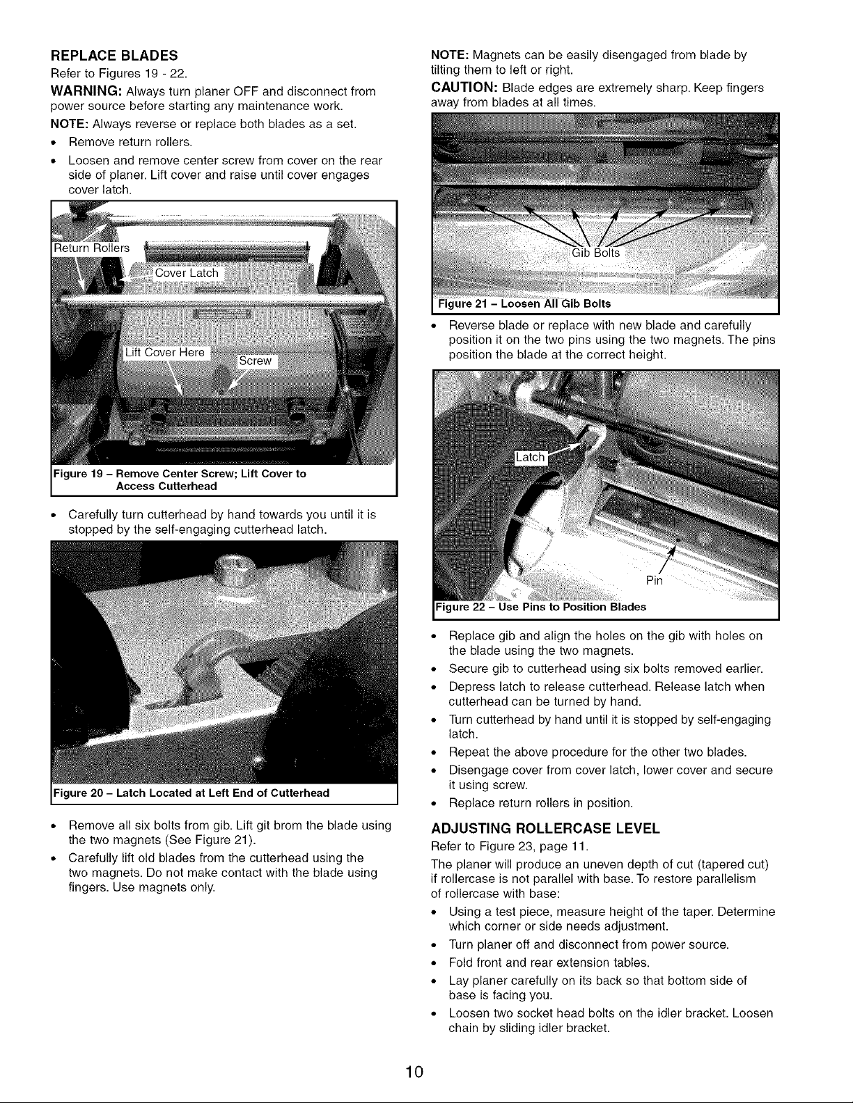
REPLACEBLADES
RefertoFigures19-22.
WARNING:AlwaysturnplanerOFFanddisconnectfrom
powersourcebeforestartinganymaintenancework.
NOTE:Alwaysreverseorreplacebothbladesasaset.
• Removereturnrollers.
° Loosenandremovecenterscrewfromcoverontherear
sideofplaner.Liftcoverandraiseuntilcoverengages
coverlatch.
NOTE: Magnets can be easily disengaged from blade by
tilting them to left or right.
CAUTION: Blade edges are extremely sharp. Keep fingers
away from blades at all times.
Figure 21 - Loosen All Gib Bolts
° Reverse blade or replace with new blade and carefully
position it on the two pins using the two magnets. The pins
position the blade at the correct height.
Figure 19 - Remove Center Screw; Lift Cover to
Access Cutterhead
* Carefully turn cutterhead by hand towards you until it is
stopped by the self-engaging cutterhead latch.
Figure 20 - Latch Located at Left End of Cutterhead
* Remove all six bolts from gib. Lift git brom the blade using
the two magnets (See Figure 21).
* Carefully lift old blades from the cutterhead using the
two magnets. Do not make contact with the blade using
fingers. Use magnets only.
Pin
Figure 22 - Use Pins to Position Blades
• Replace gib and align the holes on the gib with holes on
the blade using the two magnets.
• Secure gib to cutterhead using six bolts removed earlier.
• Depress latch to release cutterhead. Release latch when
cutterhead can be turned by hand.
• Turn cutterhead by hand until it is stopped by self-engaging
latch.
• Repeat the above procedure for the other two blades.
• Disengage cover from cover latch, lower cover and secure
it using screw.
• Replace return rollers in position.
ADJUSTING ROLLERCASE LEVEL
Refer to Figure 23, page 11.
The planer will produce an uneven depth of cut (tapered cut)
if rollercase is not parallel with base. To restore parallelism
of rollercase with base:
° Using a test piece, measure height of the taper. Determine
which corner or side needs adjustment.
° Turn planer off and disconnect from power source.
° Fold front and rear extension tables.
° Lay planer carefully on its back so that bottom side of
base is facing you.
° Loosen two socket head bolts on the idler bracket. Loosen
chain by sliding idler bracket.
10
 Loading...