

Craftsman 351217520 Owner’s Manual

Operator's Manual
MIDI LATHE
Model No.
351.217520
®
CAUTION:
Read and follow all Safety
Rules and Operating
Instructions before First
Use of this Product. Keep
this manual with tool.
Sears, Roebuck and Co., Hoffman Estates, IL 60179 U.S.A.
www.sears.com/craftsman
30897.00 Draft (05/21/09)
Warranty ......................................... 2
Safety Rules .................................... 2-3
Unpacking ...................................... 3-4
Assembly ...................................... 4-5
Installation ...................................... 5-6
Operation ..................................... 6-16
Maintenance .................................... 16
Troubleshooting .................................. 17
Parts Illustration and List ........................ 18-19
Espa_ol ...................................... 20-39
ONE-YEAR FULL WARRANTY ON CRAFTSMAN TOOL
If this Craftsman tool fails due to a defect in material or work-
manship within one year from the date of purchase, call 1-800-
4-MY-HOME®TO ARRANGE FOR FREE REPAIR (or replace-
ment if repair proves impossible).
If this tool is ever used for commercial or rental purposes, this
warranty will apply for only 90 days from the date of purchase.
This warranty gives you specific legal rights and you may
also have other rights which vary from state to state.
Sears, Roebuck and Co., Hoffman Estates, IL 60179
CAUTION: Always follow proper operating procedures as
defined in this manual -- even if you are familiar with use of
this or similar tools. Remember that being careless for even
a fraction of a second can result in severe personal injury.
WARNING: For your own safety, read all of the rules and
precautions before operating tool.
PROPOSITION 65 WARNING: Some dust created
by power sanding, sawing, grinding, drilling and other con-
struction activities contains chemicals known to the state of
California to cause cancer, birth defects or other reproductive
harm.
Some examples of these chemicals are:
• Lead from lead-based paints.
• Crystalline silica from bricks and cement and other
masonry products.
• Arsenic and chromium from chemically-treated lumber.
Your risk from these exposures vary, depending on how often
you do this type of work. To reduce your exposure to these
chemicals: work in a well ventilated area and work with
approved safety equipment. Always wear OSHA/NIOSH
approved, properly fitting face mask or respirator when
using such tools.
BE PREPARED FOR JOB
• Wear proper apparel. Do not wear loose clothing, gloves,
neckties, rings, bracelets or other jewelry which may get
caught in moving parts of machine.
• Wear protective hair covering to contain long hair.
• Wear safety shoes with non-slip soles.
© Sears, Roebuckand Co,
• Wear safety glasses complying with United States ANSI
Z87.1. Everyday glasses have only impact resistant lenses.
They are NOT safety glasses.
• Wear face mask or dust mask if operation is dusty.
• Be alert and think clearly. Never operate power tools when
tired, intoxicated or when taking medications that cause
drowsiness.
PREPARE WORK AREA FOR JOB
• Keep work area clean. Cluttered work areas invite accidents.
• Do not use power tools in dangerous environments. Do not
use power tools in damp or wet locations. Do not expose
power tools to rain.
• Work area should be properly lighted.
• Keep visitors at a safe distance from work area.
• Keep children out of workplace. Make workshop childproof.
Use padlocks, master switches or remove switch keys to
prevent any unintentional use of power tools.
• Keep power cords from coming in contact with sharp
objects, oil, grease, and hot surfaces.
TOOL SHOULD BE MAINTAINED
• Always unplug tool prior to inspection.
• Consult manual for specific maintaining and adjusting
procedures.
• Keep tool lubricated and clean for safest operation.
• Keep all parts in working order. Check to determine that
the guard or other parts will operate properly and perform
their intended function.
• Check for damaged parts. Check for alignment of moving
parts, binding, breakage, mounting and any other condition
that may affect a tool's operation.
• A guard or other part that is damaged should be properly
repaired or replaced. Do not perform makeshift repairs.
(Use parts list provided to order replacement parts.)
• Never adjust attachments while running. Disconnect power
to avoid accidental start-up.
• Have damaged or worn power cords replaced immediately.
• Keep cutting tools sharp for efficient and safest operation.
KNOW HOW TO USE TOOL
• Use right tool for job. Do not force tool or attachment to
do a job for which it was not designed.
• Disconnect tool when changing attachments.
• Avoid accidental start-up. Make sure that the tool is in the
"off" position before plugging in, turning on safety discon-
nect or activating breakers.
• Do not force tool. It will work most efficiently at the rate for
which it was designed.
• Keep hands away from chuck, centers and other moving parts.
• Never leave tool running unattended. Turn the power off
and do not leave tool until it comes to a complete stop.
• Do not overreach. Keep proper footing and balance.
• Never stand on tool. Serious injury could occur if tool is
tipped or if centers are unintentionally contacted.
• Know your tool. Learn the tool's operation, application
and specific limitations.
• Handle workpiece correctly. Mount firmly in holding
devices. Protect hands from possible injury.
• Turn machine off if workpiece splits or becomes loose.
• Use cutting tools as recommended in "Operation."
2
WARNING: For your own safety, do not operate your wood
lathe until it is completely assembled and installed according
to instructions.
PROTECTION: EYES, HANDS, FACE, BODY, EARS
• If any part of your lathe is missing, malfunctioning, or has
been damaged or broken, cease operating immediately
until the particular part is properly repaired or replaced.
• Wear ear plugs or muffs during extended periods of operation.
• Small loose pieces of wood or other objects that contact a
spinning workpiece can be propelled at very high speed.
This can be avoided by keeping the lathe clean.
• Never turn the lathe ON before clearing the bed, head and
tailstock of all tools, wood scraps, etc., except the workpiece
and related support devices for the operation planned.
• Never place your face or body in line with the chuck or
faceplate.
• Never place your fingers or hands in path of cutting tools.
• Never reach in back of the workpiece with either hand to
support the piece, remove wood scraps, or for any other
reason. Avoid awkward operations and hand positions
where a sudden slip could cause fingers or hand to
move into a spinning workpiece.
• Shut the lathe OFF and disconnect power source when
removing the faceplate, changing the center, adding or
removing an auxiliary device, or making adjustments.
• Turn key lock switch to "off" and remove key when tool
is not in use.
• If the workpiece splits or is damaged in any way, turn lathe
OFF and remove the workpiece from the holders. Discard
damaged workpiece and start with a new piece of wood.
• Use extra care when turning wood with twisted grain or
wood that is twisted or bowed i it may cut unevenly or
wobble excessively.
KNOW YOUR CUTTING TOOLS
• Dull, gummy, improperly sharpened or set cutting tools
can cause vibration and chatter during cutting operations.
Minimize potential injury by proper care of tools and
regular machine maintenance.
THINK SAFETY
Safety is a combination of operator common sense and
alertness at all times when the lathe is being used.
• For your own safety, read all rules and precautions in
the operator's manual before using this tool.
• Tighten all clamps, fixtures and tailstock before applying
power. Check to make sure that all tools and wrenches
have been removed.
• With switch off, rotate workpiece by hand to make sure
that there is adequate clearance. Start the machine on
lowest speed setting to verify that the workpiece is secure.
• For large pieces, create a rough shape on another piece
of equipment before installing on faceplate.
• Do not mount any workpieces that have splits or knots.
• Never attempt to remount a faceplate turning to the face-
plate for any reason.
• Never attempt to remount a between-centers turning if the
original centers on the turning have been altered or removed.
• When remounting a between-centers turning that has non-
altered original centers, make sure that the speed is at
the lowest setting for start-up.
• Use extra caution when mounting a between-centers turn-
ing to the faceplate, or a faceplate turning to between-cen-
ters, for secondary operations. Make sure that the speed
is at the lowest setting for start-up.
• Never perform any operation with this lathe where the
workpiece is hand-held. Do not mount a reamer, milling
cutter, drill bit, wire wheel or buffing wheel to the head-
stock spindle.
• When hand-sanding faceplate or between-centers mount-
ed workpieces, complete all sanding BEFORE removing
the workpiece from the lathe.
• Never run the spindle in the wrong direction. The cutting
tool could be pulled from your hands. The workpiece
should always turn towards the operator.
• For spindle turning, ALWAYS position the tool rest above the
centerline of the workpiece and spindle (approximately 1/8").
• Use any drill chuck accessory inthe tailstock only. Do
not mount any drill bit that extends more than 6" beyond
chuck jaws.
CAUTION: Follow safety instructions that appear on the
headstock assembly for your lathe.
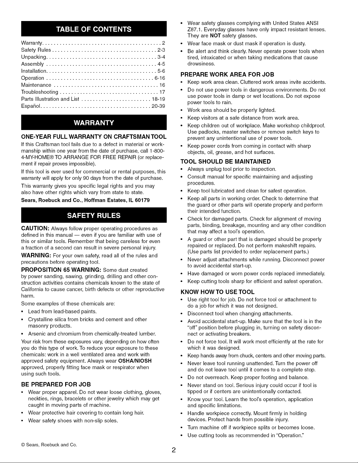
Refer to Figure 1, page 4.
Check for shipping damage or missing parts. If any parts are
damaged or missing, call 1-800-266-9079 for replacement.
Your wood lathe is shipped complete in one carton and includes
a motor. Separate all parts from packing materials and check
each one with the unpacking list to make certain all items are
accounted for before discarding any packing material.
If any parts are missing, do not attempt to assemble the
lathe, plug in the power cord, or turn the switch on until
the missing parts are obtained and properly installed.
A Lathe Assembly with Tailstock
B Faceplate
C Tool Rest Base
D Tool Rest
E Tool Holder
F Index Pin Assembly
G Live Center
H Center Removal Rod
I Point Removal Tool
J Wrench
K Spur Center
Not Shown:
M6 x 16 Pan Head Screw (2)
M6 Flat Washer (2)
IMPORTANT: The bed is coated with a protectant. To ensure
proper fit and operation, remove coating. Coating is easily
removed with mild solvents, such as mineral spirits, and a
soft cloth. Avoid getting cleaning solution on paint or any of
the rubber or plastic parts. Solvents may deteriorate these
finishes. Use soap and water on paint, plastic or rubber
components. Wipe all parts thoroughly with a clean dry
cloth. Apply paste wax to the bed.
3
• Re-install tailstock assembly onto the bed in the same
manner as the tool rest base. Secure in position with
locking lever.
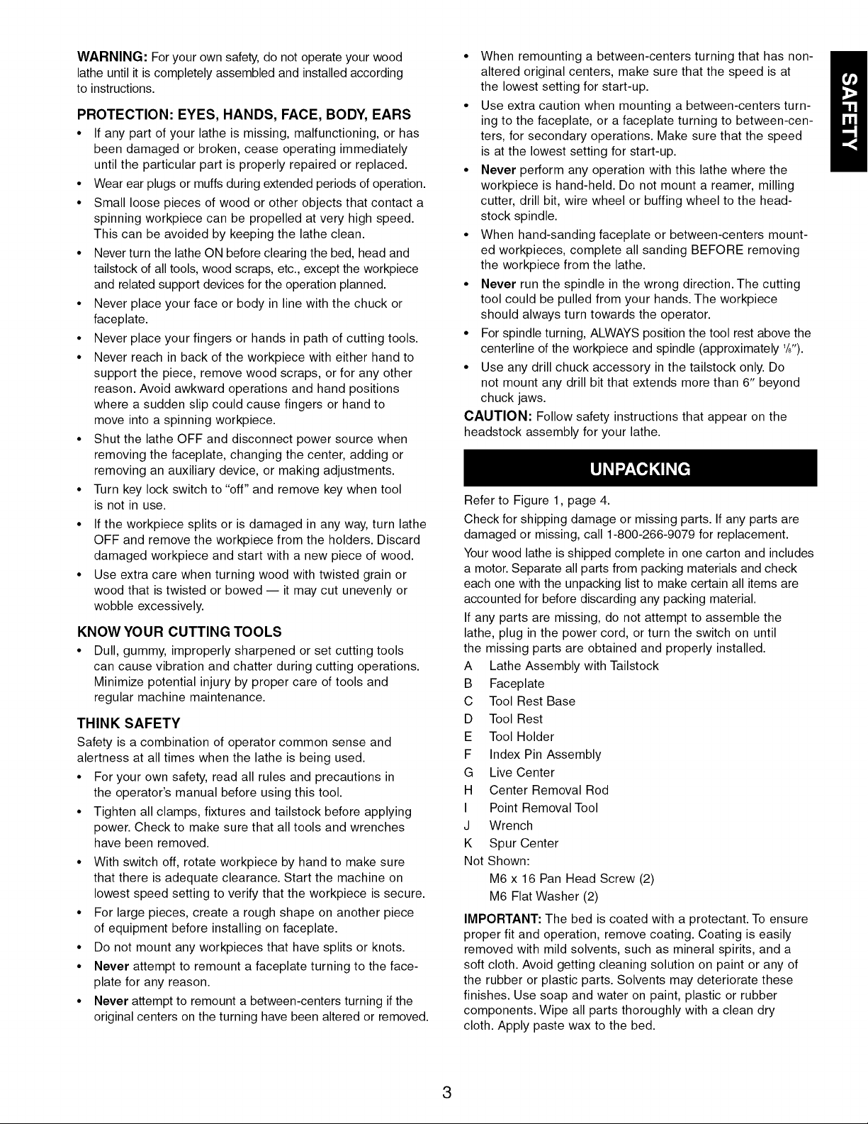
• Place tool rest into tool rest base and secure in position
with locking handle.
Tool Rest
Figure 1 - Unpacking
Refer to Figures 2 - 8.
CAUTION: Do not attempt assembly if parts are missing.
Use this manual to order replacement parts.
• Remove all components from the shipping carton and verify
against the parts list on page 3. Clean each component and
remove shipping preservatives (coatings) as required. Do
not discard packing material and shipping carton until lathe
has been set up and is running properly.
• After selecting an appropriate bench, table, or lathe stand,
set the bed towards the front and the left side.
• Remove the tailstock assembly from lathe bed. Release
locking lever and slide tailstock off lathe bed.
Figure 2
Slide the tool rest base assembly onto the bed. Make
sure clamping plate is oriented with slot in bed. Secure
the position with locking lever. To adjust the clamping plate
action, adjust locking nut clockwise to tighten and counter-
clockwise to loosen.
ig
Handle
Figure 4 - Install Tool Rest
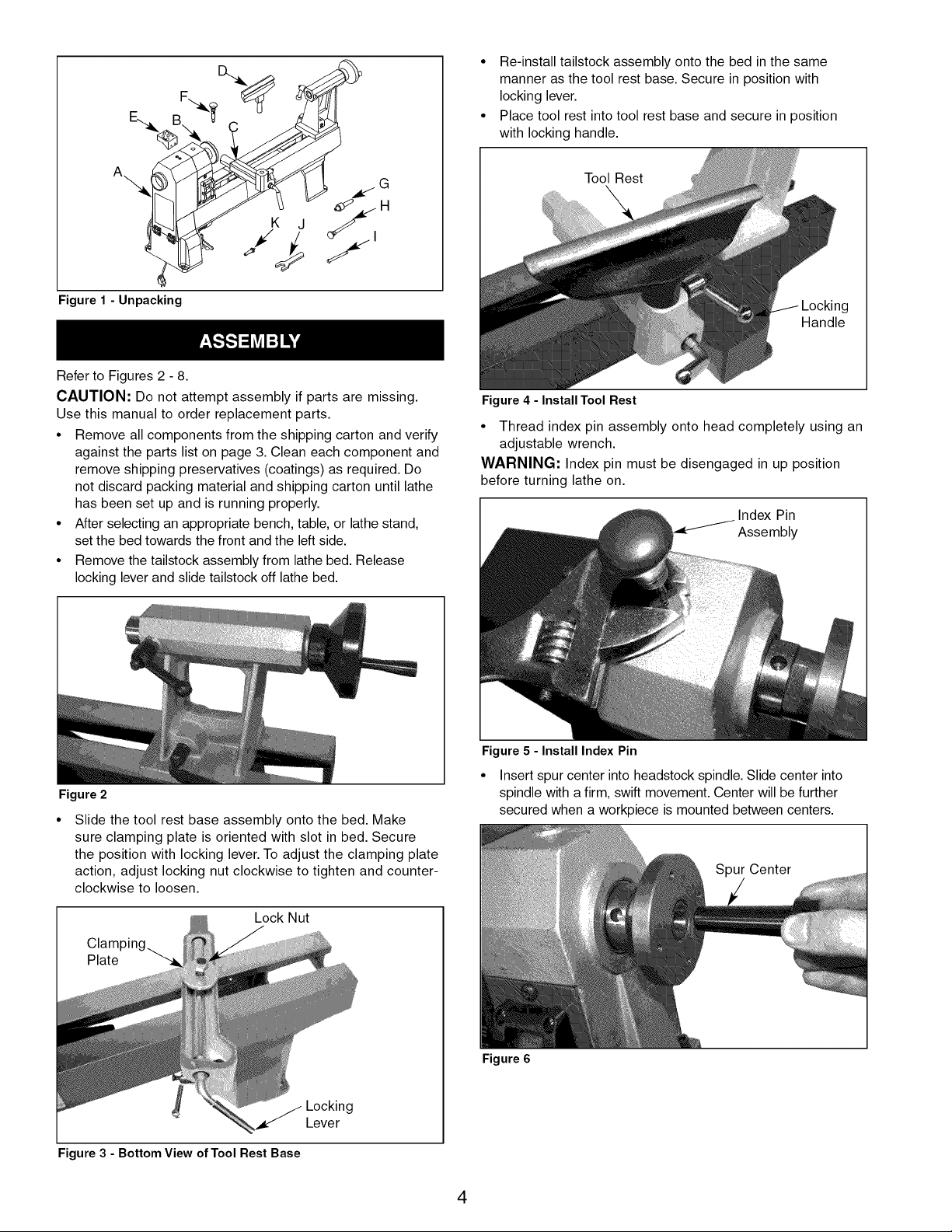
• Thread index pin assembly onto head completely using an
adjustable wrench.
WARNING: Index pin must be disengaged in up position
before turning lathe on.
I Index Pin
Assembly
Figure 5 - Install Index Pin
• Insert spur center into headstock spindle. Slide center into
spindle with a firm, swift movement. Center will be further
secured when a workpiece is mounted between centers.
Spur Center
Lock Nut
Figure 3 - Bottom View of Tool Rest Base
Figure 6
Locking
Lever
4
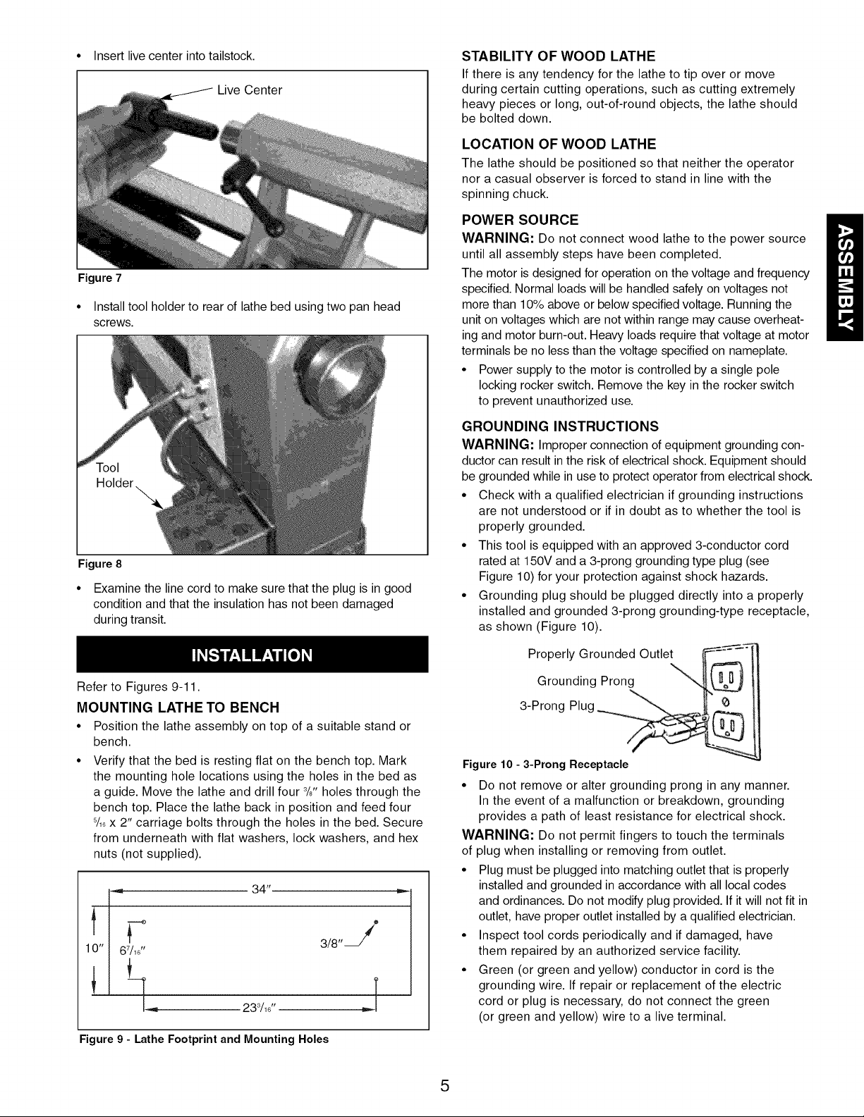
• Insert live center into tailstock.
Live Center
Figure 7
• Install tool holder to rear of lathe bed using two pan head
screws.
Figure 8
• Examine the line cord to make sure that the plug is in good
condition and that the insulation has not been damaged
during transit.
STABILITY OF WOOD LATHE
If there is any tendency for the lathe to tip over or move
during certain cutting operations, such as cutting extremely
heavy pieces or long, out-of-round objects, the lathe should
be bolted down.
LOCATION OF WOOD LATHE
The lathe should bepositioned so that neither the operator
nor a casual observer is forcedto stand in line with the
spinning chuck.
WARNING: Do not connect wood lathe to the power source
until all assembly steps have been completed.
The motor is designed for operation on the voltage and frequency
specified. Normal loads will be handled safely on voltages not
more than 10% above or below specified voltage. Running the
POWER SOURCE
unit on voltages which are not within range may cause overheat-
ing and motor burn-out. Heavy loads require that voltage at motor
terminals be no less than the voltage specified on nameplate.
• Power supply to the motor is controlled by a single pole
locking rocker switch. Remove the key in the rocker switch
to prevent unauthorized use.
GROUNDING INSTRUCTIONS
WARNING: Improper connection of equipment grounding con-
ductor can result in the risk of electrical shock. Equipment should
be grounded while in use to protect operator from electrical shock.
• Check with a qualified electrician if grounding instructions
are not understood or if in doubt as to whether the tool is
properly grounded.
• This tool is equipped with an approved 3-conductor cord
rated at 150V and a 3-prong grounding type plug (see
Figure 10) for your protection against shock hazards.
• Grounding plug should be plugged directly into a properly
installed and grounded 3-prong grounding-type receptacle,
as shown (Figure 10).
Refer to Figures 9-11.
MOUNTING LATHE TO BENCH
• Position the lathe assembly on top of a suitable stand or
bench.
• Verify that the bed is resting flat on the bench top. Mark
the mounting hole locations using the holes in the bed as
a guide. Move the lathe and drill four 3/8"holes through the
bench top. Place the lathe back in position and feed four
8/18x 2" carriage bolts through the holes in the bed. Secure
from underneath with flat washers, lock washers, and hex
nuts (not supplied).
34"
10" I 67/1_.
3/8'
T
[..,,_ 233/18"
Figure 9 - Lathe Footprint and Mounting Holes
,.J
Properly Grounded Outlet _:
Grounding Prong
3-Prong Plug _
Figure 10 - 3-Prong Receptacle
• Do not remove or alter grounding prong in any manner.
In the event of a malfunction or breakdown, grounding
provides a path of least resistance for electrical shock.
WARNING: Do not permit fingers to touch the terminals
of plug when installing or removing from outlet.
• Plug must be plugged into matching outlet that is properly
installed and grounded in accordance with all local codes
and ordinances. Do not modify plug provided. If it will not fit in
outlet, have proper outlet installed by a qualified electrician.
• Inspect tool cords periodically and if damaged, have
them repaired by an authorized service facility.
• Green (or green and yellow) conductor in cord is the
grounding wire. If repair or replacement of the electric
cord or plug is necessary, do not connect the green
(or green and yellow) wire to a live terminal.
5
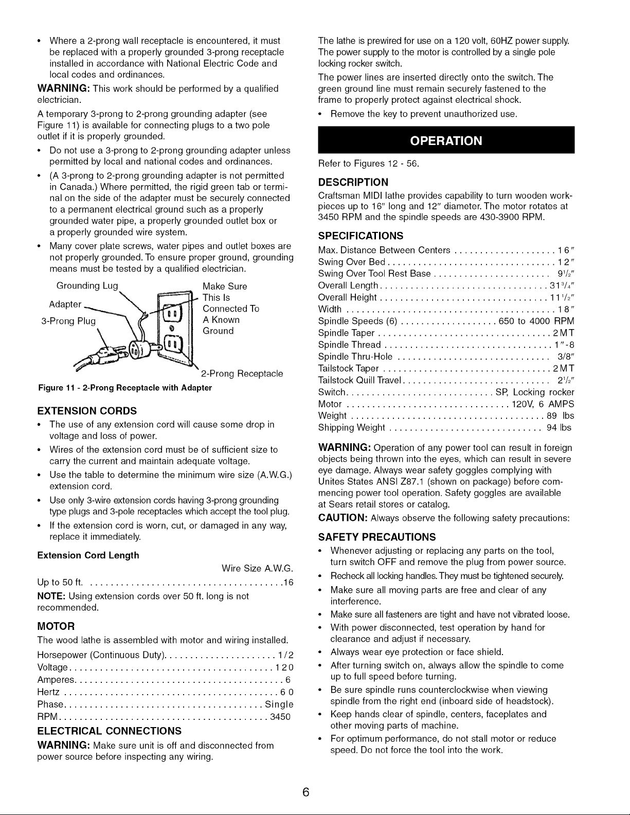
• Where a 2-prong wall receptacle is encountered, it must
be replaced with a properly grounded 3-prong receptacle
installed in accordance with National Electric Code and
local codes and ordinances.
WARNING: This work should be performed by a qualified
electrician.
A temporary 3-prong to 2-prong grounding adapter (see
Figure 11) is available for connecting plugs to a two pole
outlet if it is properly grounded.
• Do not use a 3-prong to 2-prong grounding adapter unless
permitted by local and national codes and ordinances.
• (A 3-prong to 2-prong grounding adapter is not permitted
in Canada.) Where permitted, the rigid green tab or termi-
nal on the side of the adapter must be securely connected
to a permanent electrical ground such as a properly
grounded water pipe, a properly grounded outlet box or
a properly grounded wire system.
• Many cover plate screws, water pipes and outlet boxes are
not properly grounded. To ensure proper ground, grounding
means must be tested by a qualified electrician.
Grounding Lug Make Sure
This Is
Adapter Connected To
3-Prong Plug A Known
Ground
2-Prong Receptacle
Figure 11 - 2-Prong Receptacle with Adapter
EXTENSION CORDS
• The use of any extension cord will cause some drop in
voltage and loss of power.
• Wires of the extension cord must be of sufficient size to
carry the current and maintain adequate voltage.
• Use the table to determine the minimum wire size (A.W.G.)
extension cord.
• Use only 3-wire extension cords having 3-prong grounding
type plugs and 3-pole receptacles which accept the tool plug.
• If the extension cord is worn, cut, or damaged in any way,
replace it immediately.
Extension Cord Length
Wire Size A.W.G.
Up to 50 ft....................................... 16
NOTE: Using extension cords over 50 ft. long is not
recommended.
MOTOR
The wood lathe is assembled with motor and wiring installed.
Horsepower (Continuous Duty) ...................... 1/2
Voltage ........................................ 12 0
Amperes ......................................... 6
Hertz .......................................... 6 0
Phase ....................................... Single
RPM ......................................... 3450
ELECTRICAL CONNECTIONS
WARNING: Make sure unit is off and disconnected from
power source before inspecting any wiring.
The lathe is prewired for use on a 120 volt, 60HZ power supply.
The power supply to the motor is controlled by a single pole
locking rocker switch.
The power lines are inserted directly onto the switch. The
green ground line must remain securely fastened to the
frame to properly protect against electrical shock.
• Remove the key to prevent unauthorized use.
Refer to Figures 12- 56.
DESCRIPTION
Craftsman MIDI lathe provides capability to turn wooden work-
pieces up to 16" long and 12" diameter. The motor rotates at
3450 RPM and the spindle speeds are 430-3900 RPM.
SPECIFICATIONS
Max. Distance Between Centers .................... 16"
Swing Over Bed ................................. 12"
Swing Over Tool Rest Base ....................... 91/2''
Overall Length ................................. 313/4"
Overall Height ................................. 111/2"
Width ......................................... 1 8"
Spindle Speeds (6) ................... 650 to 4000 RPM
Spindle Taper .................................. 2 MT
Spindle Thread ................................. 1"-8
Spindle Thru-Hole .............................. 3/8"
Tailstock Taper ................................. 2 MT
Tailstock Quill Travel ............................. 21/2''
Switch ............................. SP, Locking rocker
Motor ................................ 120V, 6 AMPS
Weight ...................................... 89 Ibs
Shipping Weight .............................. 94 Ibs
WARNING: Operation of any power tool can result in foreign
objects being thrown into the eyes, which can result in severe
eye damage. Always wear safety goggles complying with
Unites States ANSI Z87.1 (shown on package) before com-
mencing power tool operation. Safety goggles are available
at Sears retail stores or catalog.
CAUTION: Always observe the following safety precautions:
SAFETY PRECAUTIONS
• Whenever adjusting or replacing any parts on the tool,
turn switch OFF and remove the plug from power source.
• Recheck all locking handles. They must be tightened securely.
• Make sure all moving parts are free and clear of any
interference.
• Make sure all fasteners are tight and have not vibrated loose.
• With power disconnected, test operation by hand for
clearance and adjust if necessary.
• Always wear eye protection or face shield.
• After turning switch on, always allow the spindle to come
up to full speed before turning.
• Be sure spindle runs counterclockwise when viewing
spindle from the right end (inboard side of headstock).
• Keep hands clear of spindle, centers, faceplates and
other moving parts of machine.
• For optimum performance, do not stall motor or reduce
speed. Do not force the tool into the work.
6
ON-OFF SWITCH
Refer to Figure 56.
• The ON/OFF switch (Key No. 55) is located on the front of
the headstock. To turn lathe ON, pull switch to the up posi-
tion. To turn lathe OFF, push switch to the down position.
The lathe can be locked from unauthorized use by locking
the switch. To lock the switch:
• Turn the switch to OFF position and disconnect lathe from
power source.
• Pull the key out. The switch cannot be turned on with the
key removed.
NOTE: Should the key be removed from the switch at the ON
position, the switch can be turned to OFF position, but cannot
be turned to ON position.
• To replace key, slide key into the slot on switch until it snaps.
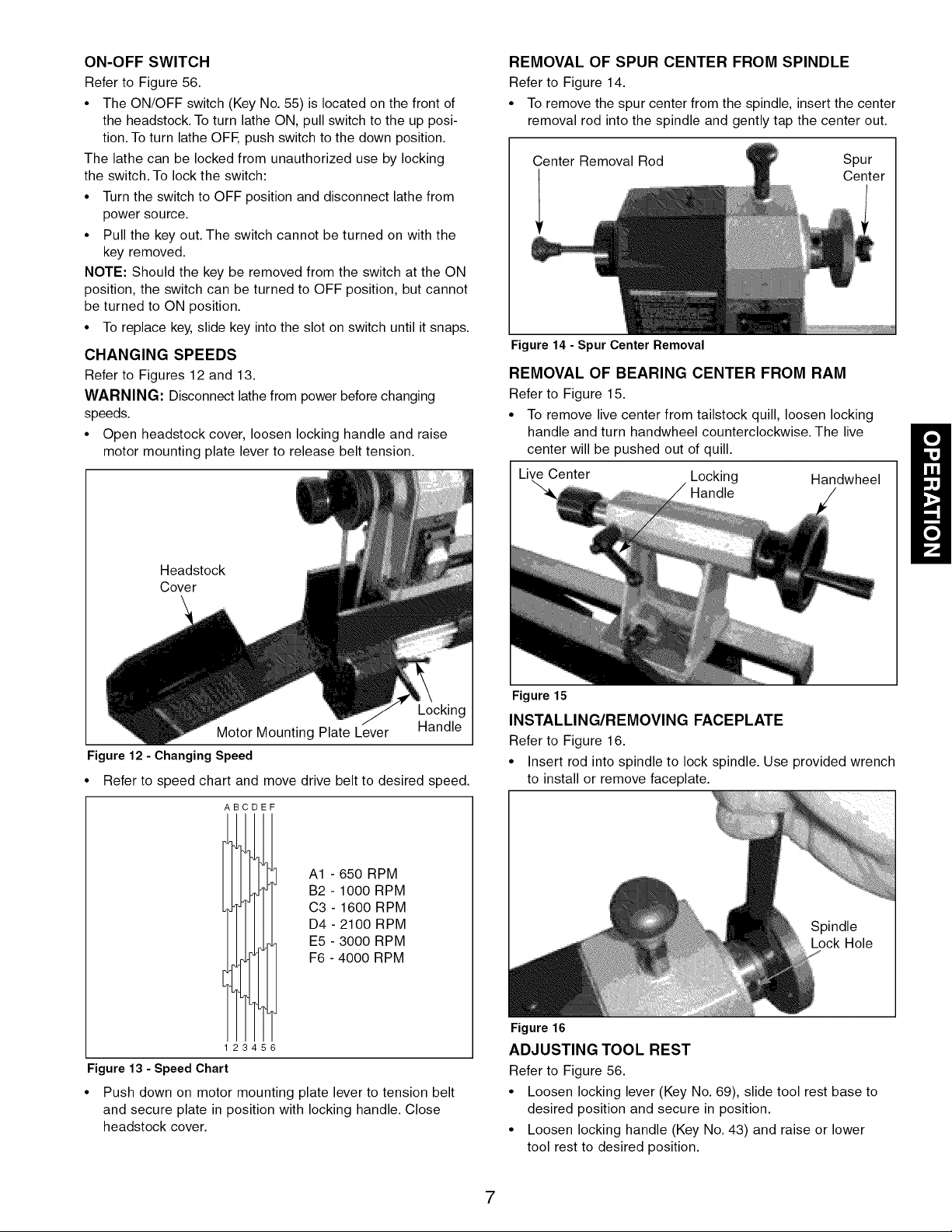
CHANGING SPEEDS
Refer to Figures 12 and 13.
WARNING: Disconnect lathe from power before changing
speeds.
• Open headstock cover, loosen locking handle and raise
motor mounting plate lever to release belt tension.
REMOVAL OF SPUR CENTER FROM SPINDLE
Refer to Figure 14.
• To remove the spur center from the spindle, insert the center
removal rod into the spindle and gently tap the center out.
Center Removal Rod Spur
Center
Figure 14 - Spur Center Removal
REMOVAL OF BEARING CENTER FROM RAM
Refer to Figure 15.
• To remove live center from tailstock quill, loosen locking
handle and turn handwheel counterclockwise. The live
center will be pushed out of quill.
Live Center Locking Handwheel
Handle
Headstock
Cover
Locking
Motor Mounting Plate Lever Handle
Figure 12 - Changing Speed
• Refer to speed chart and move drive belt to desired speed.
B DEF
A1 - 650 RPM
B2 - 1000 RPM
C3 - 1600 RPM
D4 - 2100 RPM
E5 - 3000 RPM
F6 - 4000 RPM
Figure 15
INSTALLING/REMOVING FACEPLATE
Refer to Figure 16.
• Insert rod into spindle to lock spindle. Use provided wrench
to install or remove faceplate.
2 6
Figure 13 - Speed Chart
Push down on motor mounting plate lever to tension belt
and secure plate in position with locking handle. Close
headstock cover.
Figure 16
ADJUSTING TOOL REST
Refer to Figure 56.
• Loosen locking lever (Key No. 69), slide tool rest base to
desired position and secure in position.
• Loosen locking handle (Key No. 43) and raise or lower
tool rest to desired position.
7
ADJUSTING TAILSTOCK
Refer to Figure 56.
• Loosen locking lever (Key No. 57) and slide tailstock to
desired position. Tighten lever.
• To adjust quill in or out, loosen locking handle (Key No.
60). Turn handwheel (Key No. 62) until quill is in desired
position and secure in position by tightening locking
handle.
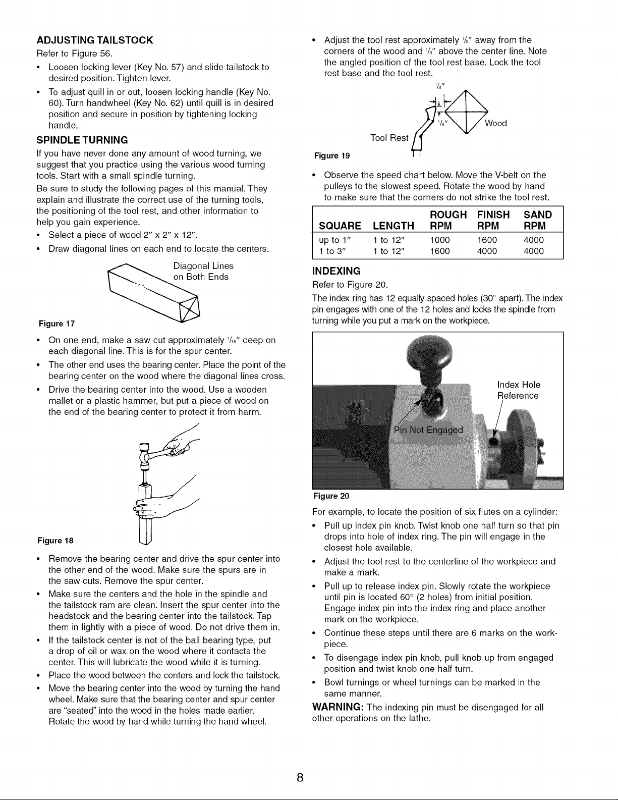
SPINDLE TURNING
If you have never done any amount of wood turning, we
suggest that you practice using the various wood turning
tools. Start with a small spindle turning.
Be sure to study the following pages of this manual. They
explain and illustrate the correct use of the turning tools,
the positioning of the tool rest, and other information to
help you gain experience.
• Select a piece of wood 2" x 2" x 12".
• Draw diagonal lines on each end to locate the centers.
Diagonal Lines
on Both Ends
Figure 17
• On one end, make a saw cut approximately 1/16ttdeep on
each diagonal line. This is for the spur center.
• The other end uses the bearing center. Place the point of the
bearing center on the wood where the diagonal lines cross.
• Drive the bearing center into the wood. Use a wooden
mallet or a plastic hammer, but put a piece of wood on
the end of the bearing center to protect it from harm.
Adjust the tool rest approximately 1/aftaway from the
corners of the wood and 1/8"above the center line. Note
the angled position of the tool rest base. Lock the tool
rest base and the tool rest.
l/stY
oo,
Figure 19
• Observe the speed chart below. Move the V-belt on the
pulleys to the slowest speed. Rotate the wood by hand
to make sure that the corners do not strike the tool rest.
ROUGH FINISH SAND
SQUARE LENGTH RPM RPM RPM
up to 1" 1to 12" 1000 1600 4000
1 to 3" 1to 12" 1600 4000 4000
INDEXING
Refer to Figure 20.
The index ring has 12 equally spaced holes (30° apart).The index
pin engages with one of the 12 holes and locks the spindle from
turning while you put a mark on the workpiece.
Index Hole
Reference
Figure 18
• Remove the bearing center and drive the spur center into
the other end of the wood. Make sure the spurs are in
the saw cuts. Remove the spur center.
• Make sure the centers and the hole in the spindle and
the tailstock ram are clean. Insert the spur center into the
headstock and the bearing center into the tailstock. Tap
them in lightly with a piece of wood. Do not drive them in.
• If the tailstock center is not of the ball bearing type, put
a drop of oil or wax on the wood where it contacts the
center. This will lubricate the wood while it is turning.
• Place the wood between the centers and lock the tailstock.
• Move the bearing center into the wood by turning the hand
wheel. Make sure that the bearing center and spur center
are "seated" into the wood in the holes made earlier.
Rotate the wood by hand while turning the hand wheel.
Figure 20
For example, to locate the position of six flutes on a cylinder:
• Pull up index pin knob. Twist knob one half turn so that pin
drops into hole of index ring. The pin will engage in the
closest hole available.
• Adjust the tool rest to the centerline of the workpiece and
make a mark.
• Pull up to release index pin. Slowly rotate the workpiece
until pin is located 60° (2 holes) from initial position.
Engage index pin into the index ring and place another
mark on the workpiece.
• Continue these steps until there are 6 marks on the work-
piece.
• To disengage index pin knob, pull knob up from engaged
position and twist knob one half turn.
• Bowl turnings or wheel turnings can be marked in the
same manner.
WARNING: The indexing pin must be disengaged for all
other operations on the lathe.
8
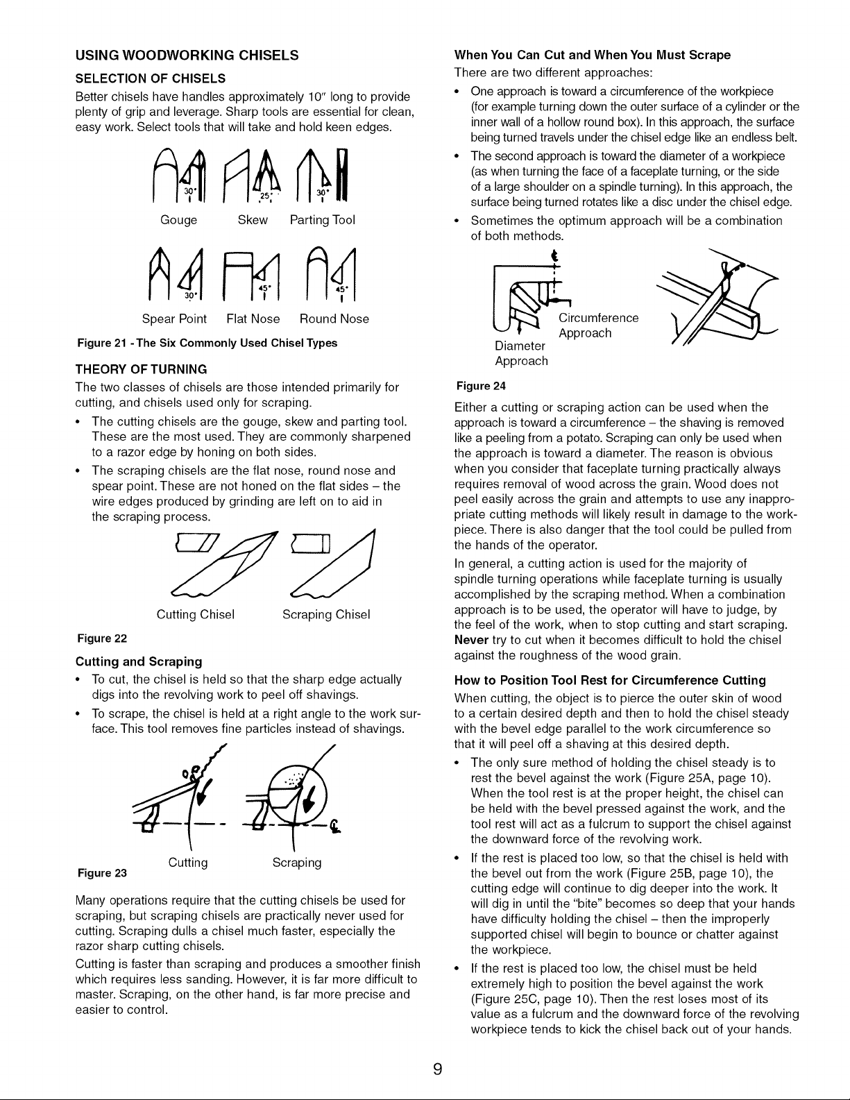
USING WOODWORKING CHISELS
SELECTION OF CHISELS
Better chisels have handles approximately 10" long to provide
plenty of grip and leverage. Sharp tools are essential for clean,
easy work. Select tools that will take and hold keen edges.
Gouge Skew Parting Tool
When You Can Cut and When You Must Scrape
There are two different approaches:
• One approach is toward a circumference of the workpiece
(for example turning down the outer surface of a cylinder or the
inner wall of a hollow round box). In this approach, the surface
being turned travels under the chisel edge like an endless belt.
• The second approach is toward the diameter of a workpiece
(as when turning the face of afaceplate turning, or the side
of a large shoulder on a spindle turning). Inthis approach, the
surface being turned rotates like a disc under the chisel edge.
• Sometimes the optimum approach will be a combination
of both methods.
Spear Point Flat Nose
Figure 21 -The Six Commonly Used Chisel Types
THEORY OF TURNING
The two classes of chisels are those intended primarily for
cutting, and chisels used only for scraping.
• The cutting chisels are the gouge, skew and parting tool.
These are the most used. They are commonly sharpened
to a razor edge by honing on both sides.
• The scraping chisels are the flat nose, round nose and
spear point. These are not honed on the flat sides - the
wire edges produced by grinding are left on to aid in
the scraping process.
Cutting Chisel Scraping Chisel
Figure 22
Cutting and Scraping
• To cut, the chisel is held so that the sharp edge actually
digs into the revolving work to peel off shavings.
• To scrape, the chisel is held at a right angle to the work sur-
face. This tool removes fine particles instead of shavings.
Figure 23
Many operations require that the cutting chisels be used for
scraping, but scraping chisels are practically never used for
cutting. Scraping dulls a chisel much faster, especially the
razor sharp cutting chisels.
Cutting is faster than scraping and produces a smoother finish
which requires less sanding. However, it is far more difficult to
master. Scraping, on the other hand, is far more precise and
easier to control.
Cutting Scraping
Round Nose
Ap__Cr; _omfehence
Diameter
Approach
Figure24
Either a cutting or scraping action can be used when the
approach is toward a circumference - the shaving is removed
like a peeling from a potato. Scraping can only be used when
the approach is toward a diameter. The reason is obvious
when you consider that faceplate turning practically always
requires removal of wood across the grain. Wood does not
peel easily across the grain and attempts to use any inappro-
priate cutting methods will likely result in damage to the work-
piece. There is also danger that the tool could be pulled from
the hands of the operator.
In general, a cutting action is used for the majority of
spindle turning operations while faceplate turning is usually
accomplished by the scraping method. When a combination
approach is to be used, the operator will have to judge, by
the feel of the work, when to stop cutting and start scraping.
Never try to cut when it becomes difficult to hold the chisel
against the roughness of the wood grain.
How to Position Tool Rest for Circumference Cutting
When cutting, the object is to pierce the outer skin of wood
to a certain desired depth and then to hold the chisel steady
with the bevel edge parallel to the work circumference so
that it will peel off a shaving at this desired depth.
• The only sure method of holding the chisel steady is to
rest the bevel against the work (Figure 25A, page 10).
When the tool rest is at the proper height, the chisel can
be held with the bevel pressed against the work, and the
tool rest will act as a fulcrum to support the chisel against
the downward force of the revolving work.
• If the rest is placed too low, so that the chisel is held with
the bevel out from the work (Figure 25B, page 10), the
cutting edge will continue to dig deeper into the work. It
will dig in until the "bite" becomes so deep that your hands
have difficulty holding the chisel - then the improperly
supported chisel will begin to bounce or chatter against
the workpiece.
• If the rest is placed too low, the chisel must be held
extremely high to position the bevel against the work
(Figure 25C, page 10). Then the rest loses most of its
value as a fulcrum and the downward force of the revolving
workpiece tends to kick the chisel back out of your hands.
9
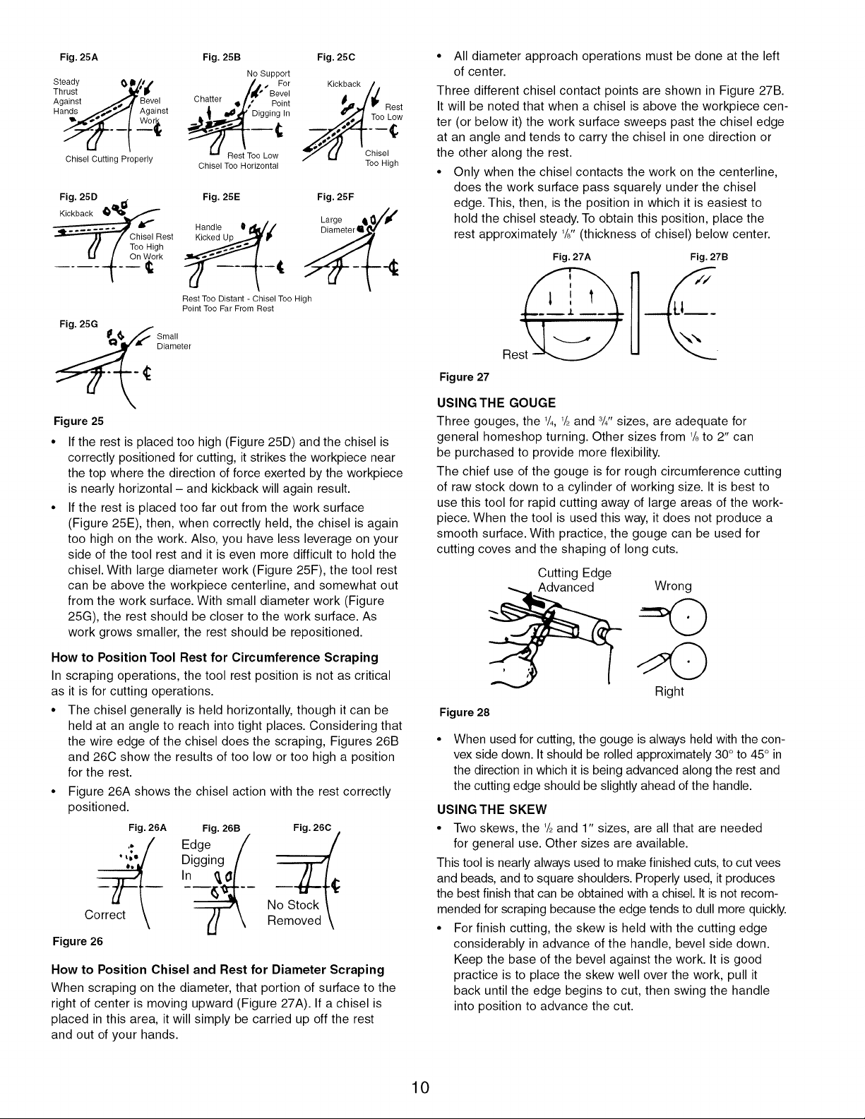
Fig. 25A
Steady (_ Im/a i
Thrust "_'_
Against __,,_o.A Bevel
Hands _._"'_/ Against
Chisel Cutting Properly
Fig. 25D
Kickback __
.
Too High
On Work
Chisel Rest
Fig. 25B
No Support
/,t.'BF,;r,
Chatter ! ;," Pgi/t
Chisel Too Horizontal
Fig. 25E
Handle 0d_'./
Rest Too Distant - Chisel Too High
Point Too Far From Rest
o Lo
Fig. 25C
Kickback
Fig. 25F
Rest
Too Low
Chisel
Too High
• All diameter approach operations must be done at the left
of center.
Three different chisel contact points are shown in Figure 27B.
It will be noted that when a chisel is above the workpiece cen-
ter (or below it) the work surface sweeps past the chisel edge
at an angle and tends to carry the chisel in one direction or
the other along the rest.
• Only when the chisel contacts the work on the centerline,
does the work surface pass squarely under the chisel
edge. This, then, is the position in which it is easiest to
hold the chisel steady. To obtain this position, place the
rest approximately 1/8"(thickness of chisel) below center.
Fig. 27A
Fig. 27B
U___
es@
_ Sti_leter
Figure25
If the rest is placed too high (Figure 25D) and the chisel is
correctly positioned for cutting, it strikes the workpiece near
the top where the direction of force exerted by the workpiece
is nearly horizontal - and kickback will again result.
If the rest is placed too far out from the work surface
(Figure 25E), then, when correctly held, the chisel is again
too high on the work. Also, you have less leverage on your
side of the tool rest and it is even more difficult to hold the
chisel. With large diameter work (Figure 25F), the tool rest
can be above the workpiece centerline, and somewhat out
from the work surface. With small diameter work (Figure
25G), the rest should be closer to the work surface. As
work grows smaller, the rest should be repositioned.
How to Position Tool Rest for Circumference Scraping
In scraping operations, the tool rest position is not as critical
as it is for cutting operations.
• The chisel generally is held horizontally, though it can be
held at an angle to reach into tight places. Considering that
the wire edge of the chisel does the scraping, Figures 26B
and 26C show the results of too low or too high a position
for the rest.
• Figure 26A shows the chisel action with the rest correctly
positioned.
Fig. 26A Fig. 26B Fig. 260
.... Digging
In
.; Edge N_
Correct
Figure 26
How to Position Chisel and Rest for Diameter Scraping
When scraping on the diameter, that portion of surface to the
right of center is moving upward (Figure 27A). If a chisel is
placed in this area, it will simply be carried up off the rest
and out of your hands.
Figure 27
USING THE GOUGE
Three gouges, the 1/4, 1/2and 8/4"sizes, are adequate for
general homeshop turning. Other sizes from 1/8to 2" can
be purchased to provide more flexibility.
The chief use of the gouge is for rough circumference cutting
of raw stock down to a cylinder of working size. It is best to
use this tool for rapid cutting away of large areas of the work-
piece. When the tool is used this way, it does not produce a
smooth surface. With practice, the gouge can be used for
cutting coves and the shaping of long cuts.
Cutting Edge
Advanced
Wrong
Right
Figure 28
When used for cutting, the gouge is always held with the con-
vex side down. Itshould be rolled approximately 30° to 45° in
the direction in which it is being advanced along the rest and
the cutting edge should be slightly ahead of the handle.
USING THE SKEW
• Two skews, the 1/2and 1" sizes, are all that are needed
for general use. Other sizes are available.
This tool is nearly always used to make finished cuts, to cut vees
and beads, and to square shoulders. Properly used, it produces
the best finish that can be obtained with a chisel. It is not recom-
mended for scraping because the edge tends to dull more quickly.
• For finish cutting, the skew is held with the cutting edge
considerably in advance of the handle, bevel side down.
Keep the base of the bevel against the work. It is good
practice is to place the skew well over the work, pull it
back until the edge begins to cut, then swing the handle
into position to advance the cut.
10
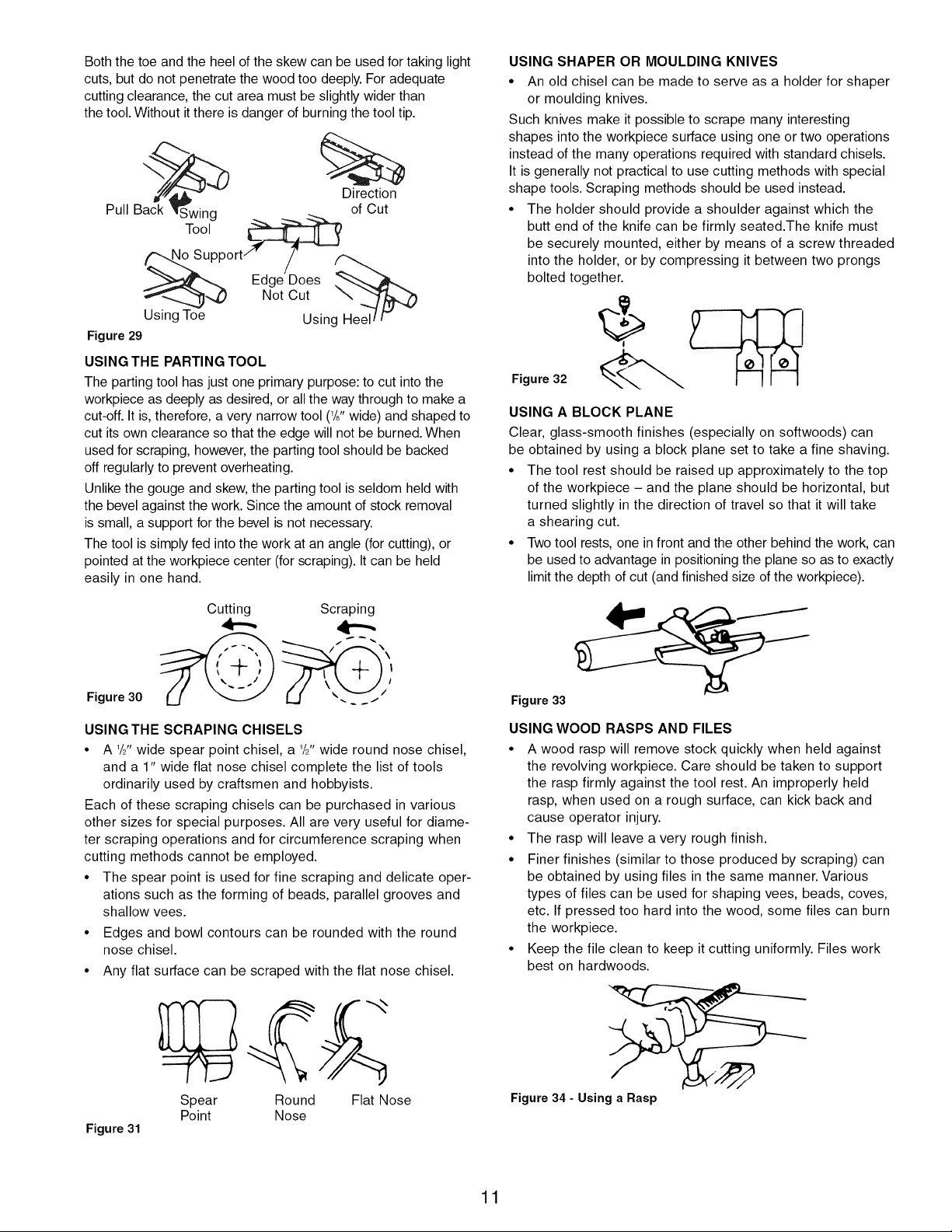
Both the toe and the heel of the skew can be used for taking light
cuts, but do not penetrate the wood too deeply. For adequate
cutting clearance, the cut area must be slightly wider than
the tool. Without it there is danger of burning the tool tip.
Direction
Back Swing __ --_ .__
Pull Tool _ of Cut
_upport/' /
Edge Does
T_-_ _,,_) Not Cut
Using Toe Using
Figure 29
USING THE PARTING TOOL
The parting tool has just one primary purpose: to cut into the
workpiece as deeply as desired, or all the way through to make a
cut-off. It is, therefore, a very narrow tool (l/j, wide) and shaped to
cut its own clearance so that the edge will not be burned. When
used for scraping, however, the parting tool should be backed
off regularly to prevent overheating.
Unlike the gouge and skew, the parting tool is seldom held with
the bevel against the work. Since the amount of stock removal
is small, a support for the bevel is not necessary.
The tool is simply fed into the work at an angle (for cutting), or
pointed at the workpiece center (for scraping). It can be held
easily in one hand.
USING SHAPER OR MOULDING KNIVES
• An old chisel can be made to serve as a holder for shaper
or moulding knives.
Such knives make it possible to scrape many interesting
shapes into the workpiece surface using one or two operations
instead of the many operations required with standard chisels.
It is generally not practical to use cutting methods with special
shape tools. Scraping methods should be used instead.
• The holder should provide a shoulder against which the
butt end of the knife can be firmly seated.The knife must
be securely mounted, either by means of a screw threaded
into the holder, or by compressing it between two prongs
bolted together.
Figure 32
USING A BLOCK PLANE
Clear, glass-smooth finishes (especially on softwoods) can
be obtained by using a block plane set to take a fine shaving.
• The tool rest should be raised up approximately to the top
of the workpiece - and the plane should be horizontal, but
turned slightly in the direction of travel so that it will take
a shearing cut.
• Two tool rests, one in front and the other behind the work, can
be used to advantage in positioning the plane so as to exactly
limit the depth of cut (and finished size of the workpiece).
Cutting Scraping
,4--,,
Figure 30
USING THE SCRAPING CHISELS
• A 1/21twide spear point chisel, a 1/2"wide round nose chisel,
and a 1" wide flat nose chisel complete the list of tools
ordinarily used by craftsmen and hobbyists.
Each of these scraping chisels can be purchased in various
other sizes for special purposes. All are very useful for diame-
ter scraping operations and for circumference scraping when
cutting methods cannot be employed.
• The spear point is used for fine scraping and delicate oper-
ations such as the forming of beads, parallel grooves and
shallow vees.
• Edges and bowl contours can be rounded with the round
nose chisel.
• Any flat surface can be scraped with the flat nose chisel.
Figure 33
USING WOOD RASPS AND FILES
• A wood rasp will remove stock quickly when held against
the revolving workpiece. Care should be taken to support
the rasp firmly against the tool rest. An improperly held
rasp, when used on a rough surface, can kick back and
cause operator injury.
• The rasp will leave a very rough finish.
• Finer finishes (similar to those produced by scraping) can
be obtained by using files in the same manner. Various
types of files can be used for shaping vees, beads, coves,
etc. If pressed too hard into the wood, some files can burn
the workpiece.
• Keep the file clean to keep it cutting uniformly. Files work
best on hardwoods.
Figure 31
Spear Round Flat Nose
Point Nose
Figure34 - Using a Rasp
11
HAND POSITIONS
When using any of the chisels, the hand takes a natural position
on the tool handle.This position may be near the middle of the
handle or towards the end, depending upon the amount of
leverage required. The position of the hand near the tool rest is
a matter of individual preference, but there are three generally
accepted positions, each best for certain types of operations.
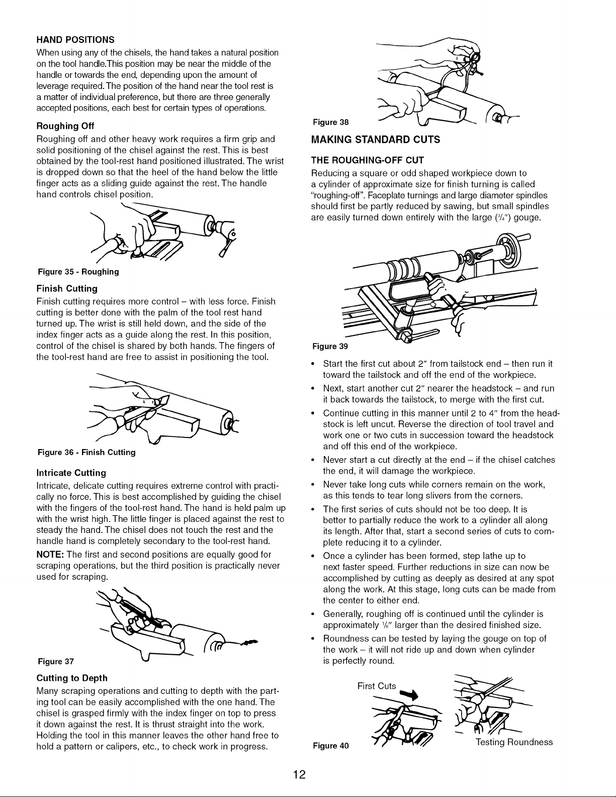
Roughing Off
Roughing off and other heavy work requires a firm grip and
solid positioning of the chisel against the rest. This is best
obtained by the tool-rest hand positioned illustrated. The wrist
is dropped down so that the heel of the hand below the little
finger acts as a sliding guide against the rest. The handle
hand controls chisel position.
Figure 35 - Roughing
Finish Cutting
Finish cutting requires more control - with less force. Finish
cutting is better done with the palm of the tool rest hand
turned up. The wrist is still held down, and the side of the
index finger acts as a guide along the rest. In this position,
control of the chisel is shared by both hands. The fingers of
the tool-rest hand are free to assist in positioning the tool.
Figure 36 - Finish Cutting
Intricate Cutting
Intricate, delicate cutting requires extreme control with practi-
cally no force. This is best accomplished by guiding the chisel
with the fingers of the tool-rest hand. The hand is held palm up
with the wrist high. The little finger is placed against the rest to
steady the hand. The chisel does not touch the rest and the
handle hand is completely secondary to the tool-rest hand.
NOTE: The first and second positions are equally good for
scraping operations, but the third position is practically never
used for scraping.
Figure 37
Cutting to Depth
Many scraping operations and cutting to depth with the part-
ing tool can be easily accomplished with the one hand. The
chisel is grasped firmly with the index finger on top to press
it down against the rest. It is thrust straight into the work.
Holding the tool in this manner leaves the other hand free to
hold a pattern or calipers, etc., to check work in progress.
Figure38
MAKING STANDARD CUTS
THE ROUGHING-OFF CUT
Reducing a square or odd shaped workpiece down to
a cylinder of approximate size for finish turning is called
"roughing-off". Faceplate turnings and large diameter spindles
should first be partly reduced by sawing, but small spindles
are easily turned down entirely with the large (3/4")gouge.
Figure 39
• Start the first cut about 2" from tailstock end - then run it
toward the tailstock and off the end of the workpiece.
• Next, start another cut 2" nearer the headstock - and run
it back towards the tailstock, to merge with the first cut.
• Continue cutting in this manner until 2 to 4" from the head-
stock is left uncut. Reverse the direction of tool travel and
work one or two cuts in succession toward the headstock
and off this end of the workpiece.
• Never start a cut directly at the end - if the chisel catches
the end, it will damage the workpiece.
• Never take long cuts while corners remain on the work,
as this tends to tear long slivers from the corners.
• The first series of cuts should not be too deep. It is
better to partially reduce the work to a cylinder all along
its length. After that, start a second series of cuts to com-
plete reducing it to a cylinder.
• Once a cylinder has been formed, step lathe up to
next faster speed. Further reductions in size can now be
accomplished by cutting as deeply as desired at any spot
along the work. At this stage, long cuts can be made from
the center to either end.
• Generally, roughing off is continued until the cylinder is
approximately 1/8"larger than the desired finished size.
• Roundness can be tested by laying the gouge on top of
the work - it will not ride up and down when cylinder
is perfectly round.
First Cuts
Figure 40
Testing Roundness
12
 Loading...