

Craftsman 351217450 Owner’s Manual

Operator's Manual
CRRFTSMRN°I
5"
PLANER/MOLDER WITH DUST COLLECTION
Model No.
351.217450
Updated
CAUTION: Read and follow all Safety Rules and Operating Instructions
before First Use of this Product.
Sears, Roebuck and Co., Hoffman Estates, IL 60179 U.S.A.
•wv,_N.sears.co nllcnsftsman
20382.03 Draft (12/23/2003)
Warranty.................................... 2
Safety Rules ............................... 2-3
Unpacking .................................. 3
Assembly ................................. 3-5
Installation................................. 5-6
Operation ................................ 6-14
Maintenance ............................. 15-16
Troubleshooting........................... 17-18
Parts Illustrationand List ................... 19-26
EspaSol................................. 26-43
FU LL ONE YEAR WARRANTY
If this productfailsdue to a defect in material or work-
manship withinone year from the date of purchase,
Sears will at its option repair or replace it free of
charge. Contact your nearest Sears Service Center
(1-800-4-MY-HOME) to arrange for product repair, or
returnthis productto place of purchasefor replacement.
If this product is used for commercial or rental purpos-
es, this warranty will apply for 90 days from the date of
purchase.
This warranty applies only while this productis used in
the United States.
This warrantygives you specificlegal rights and you may
also have other rightswhich vary from state to state.
Sears, Roebuck and Co., Dept. 8t7WA, Hoffman
Estates, IL 60179
WARNING: Foryour own safety, read all of the rules
and precautions before operating tool.
CAUTION: Always follow proper operating procedures
as defined in this manual even if you are familiarwith
use ofthis or similar tools. Remember that being care-
lessfor even a fractionof a second can resultin severe
personal injury.
BE PREPARED FOR JOB
• Wear proper apparel. Do not wear loose clothing,
gloves, neckties, rings, bracelets or otherjewelry
which may get caught in movingparts of machine.
• Wear protective hair coveringto contain long hair.
• Wear safety shoes withnon-slip soles.
• Wear safety glasses complying with United States
ANSI Z87.1. Everyday glasses have onlyimpact
resistantlenses.They are NOT safety glasses.
• Wear face mask or dust mask ifoperation is dusty.
• Be alert and think clearly.Never operate power tools
when tired, intoxicatedor when taking medications
that cause drowsiness.
O Seam, Roebuck and Co.
PREPARE WORK AREA FOR JOB
• Keep work area clean.Clutteredwork areas invite
accidents. -, -.
• Do not use power tools in dangerous environments.
• Do not use power tools in damp or wet locations. Do
not expose power tools to rain.
• Work area should be proper{y lighted.
• Proper electrical receptacle shouldbe available for
tool.Three prong plug should be pluggeddirectly
intoproperly grounded, thrae-prong receptacle.
• Extension cords should have a groundingprong and
the three wires ofthe extensioncord should be of
the correct gauge.
• Keep visitors at a safe distance from work area.
• Keepchildren outofworkptace.Make worl_shop child-
proof. Use padlocks, master switchesor remove switch
keysto prevent any unintentional use ofpower tools.
TOOL SHOULD BE MAINTAINED i
Always unplugtool priorto inspection.
• Consultmanualfor specificmaintainingand adjust-
ingprocedures. :
• Keep tool lubricatedand clean for safestoperation.
• Remove adjustingtools. Form habitof checking to
see that adjustingtools are removedbef(_raswitch-
ing machineon.
• Keepall parts inworking order. Check to determine
that the guard or other parts will operate i)ropedy
and performtheir intendedfunction. ,
• Checkfor damaged pads, Check for aiignmentof
movingparts, binding,breakage, mountingand any
otherconditionthat may affect a tool'soperation.
• A guard or other part that is damaged should be
properlyrepairedor replaced. Do not perform
makeshiftrepairs.(Use parts listprovidedto order
replacement pads.)
KNOW HOW TO USE TOOL
• Use dght toolforjob. Do notforcetool orattachment
to do a jobfor which it was not designed.
• Disconnecttoolwhen changing blades. ,
• Avoidaccidental stad-up,Make surethatlthe switch
is in the OFF positionbefore pluggingin. _
• Donot force tool.It will work mostefficientlyat the
ratafor which it was designed,
• Keep hands away from movingpartsand Cutting
surfaces. • :'
• Never leave tool runningunattended.Turnthe power
offand do not leave tool untilitcomes to a complete
stop.
• Do not overreach.Keep properfooting and balance.
• Never standon tool.Seriousinjurycould occurif tool is
tippedor if blade is unintentionallycontacted.
• Knowyourtool. Learn the tool'soperation,applica-
tionand speciticlimitations.... :_,_
• Use recommendedaccessodes (refe=:topage 25).
Use of improperacoessodesmay cause riskof
injuryto persons. : -*L_
2
• Handle workpiece correctly.Protect handsfrom
possibleinjury.
• Turn machine off if it jams. Bladejams when it digs
too deeply into workpiece. (Motor force keeps it
stuck in the work.)
• Always keep drive, cutterhead and blade guards in
place and in proper operating condition.
• Feed work into blade or cutter againstdirectionof
rotation.
CAUTION: Think safety! Safety isa combination of
operator common sense and alertness at alltimes
when tool is being used.
WARNING: Do not attemptto operate tool untilit is
completely assembled accordingto the instructions.
Refer to Figures 1 and 2.
Check for shipping damage. If damage has occurred,a
claim must be filedwith carder. Check for complete-
ness. Immediately report missingparts to dealer.
The planer/molder comes assembledas one unit.
Additional parts which need to be fastened to
planer/molder shouldbe located and accounted for
beforeassembling.
A. Handle Assembly
B. 5-0.8 x 25mm Socket Head Bolt
C. Plug
D. Roller Height AdjustmentWrench
E. Dust Chute
F. 6-1.0 x 25mm Socket Pan Head Screw
G. Roller (2)
H. Molding Gib and Spacer Set (4)
Not Shown:
Half Bag Dust Collection Set
Auxiliary Table Hardware Bag (Part No. 21012.00)
includes:
• #10-32 x 23/d' Socket Head Bolt(2)
• #10 FlatWasher (2)
• Clamp (2)
• 1/,-20x 11/," Wing Screw (4)
• 1/4"Flat Washer (4)
• Table Insert (4)
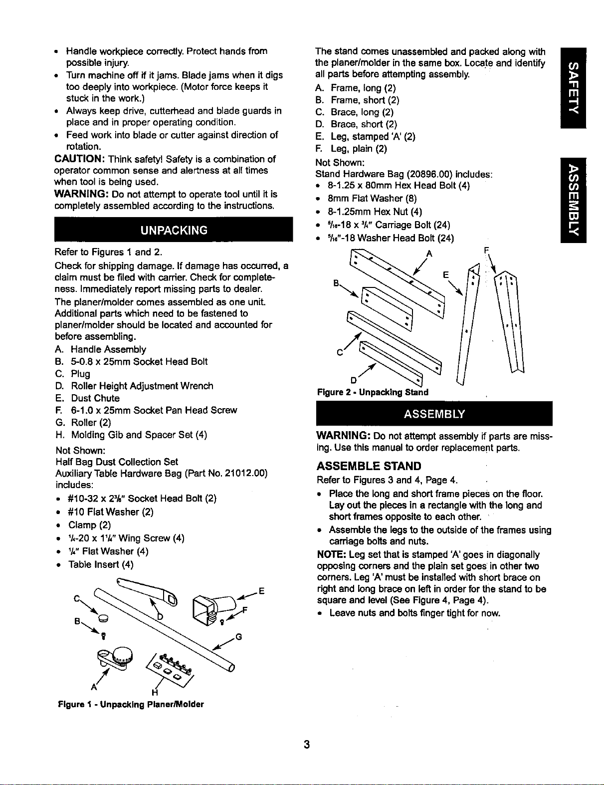
The stand comes unassemb_edand packed along with
the planer/molderin the same box. Locate and identify
all parts beforeattemptingassembly.
A. Frame, long (2)
B. Frame, short (2)
C. Brace, long (2)
D. Brace, short(2)
E. Leg, stamped 'A' (2)
F. Leg, plain (2)
Not Shown:
Stand Hardware Bag (20896.00) includes:
• 8-1.25 x 80ram Hex Head Bolt (4)
• 8mm Flat Washer (8)
• 8-1.25mm Hex Nut (4)
• S/le-18 X =/4" Carriage Bolt(24)
• 51_e"-18Washer Head Bolt (24)
A
F
E
Figure 2 - Unpacking Stand
WARNING: Do not attemptassembly if parts are miss-
ing. Use this manual to order replacement parts.
ASSEMBLE STAND
Refer to Figures 3 and 4, Page 4.
• Place the long and shortframe pieces on the floor.
Layout the pieces in a rectanglewiththe long and
shortframes oppositeto each other. '
• Assemble the legs to the outsideof the frames using
cardage boltsand nuts.
NOTE: Leg set that isstamped 'A' goes in diagonally
opposingcorners and the plainset goes'inother two
corners. Leg 'A'must be installedwith short brace on
rightand long brace on left in order for the stand to be
square and level(See Figure4, Page 4).
• Leave nuts and bolts finger tightfor now.
Figure1 - UnpackingPlaner/Molder
3
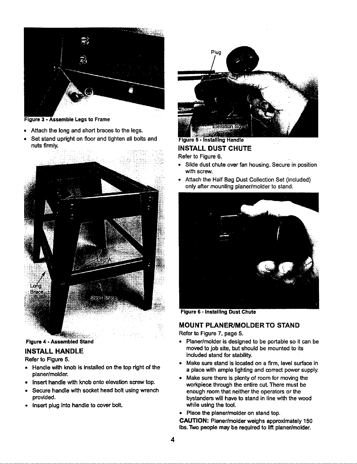
Figure3 - AssembleLegsto Frame
• Attach the long and short braces to the legs.
• Set stand upright on floor and tighten all boltsand
nuts firmly.
Figure5 - InstallingHandle
INSTALL DUST CHUTE
Refer to Figure 6,
• Slide dust chute over fan housing. Secure in position
with screw.
• Attach the Half Beg Dust Collection Set (included)
only after mounting planer/molder to stand.
Figure4 - Assembled Stand
INSTALL HANDLE
Refer to Figure 5.
• Handlewith knob is installedon the top rightof the
planer/molder.
• Insert handle with knob onto elevationscrewtop.
• Secure handle with sockethead bolt usingwrench
provided,
• Insert plug into handle to oover bolt.
Figure 6 - Installing Dust Chute
MOUNT PLANERJMOLDER TO STAND
Refer to Figure 7, page 5.
• Planer/molderis designed to be portable so itcan be
movedtojob site, but should be mountedto its
includedstand for stability.
• Make sure stand is located on a firm, level surface in
a place with ample lightingand correct powersupply.
• Make sure there is plenty of roomfor movingthe
workpiece throughthe entire cut.There must be
enoughroomthat neither the operators or the
bystanderswill have to stand in linewith the wood
whileusingthe tool.
• Place the planer/molderon stand top.
CAUTION: Planer/molder weighs approximately150
Ibs.Two people may be required to liftplaner/molder.
4
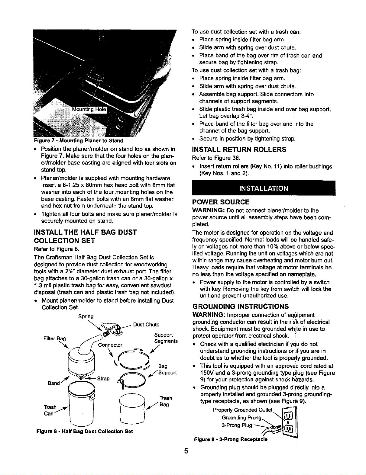
Figure 7 - Mounting Planer to Stand
• Position the planedmolder on stand top as shown in
Figure 7. Make sure that the four holes on the plan-
edmolder base casting are aligned with four slots on
standtop.
• Planer/molder is supplied with mounting hardware.
Insert e 8-1.25 x 80mm he)( head bolt with 8mm fiat
washer into each of the four mounting holes on the
base casting. Fasten bolts with an 8mm fiat washer
and hex nut from underneath the stand top.
• Tighten ell four bolts and make sure planer/molder is
securely mounted on stand.
INSTALL THE HALF BAG DUST
COLLECTION SET
Refer to Figure 8.
The Craftsman Half Bag Dust ConectionSet is
designedto providedust collectionfor woodworking
toolswith a 21/2"diameter dust exhaustport.The filter
bag attaches to a 30-gallon trash can or a 30-gallon x
1.3 milplastic trash bag for easy, convenientsawdust
disposal(trash can and plastic trash bag not included).
• Mountplaner/molder to stand before installingDust
CollectionSet.
Spring
Filter
__ DustChute
J'_- nne r Segments
/' co. /
Support
/s,.port
To use dust collection set with a trash can:
• Place spring insidefilter bag arm.
• Slide arm with spring over dust chute,
• Place band of the bag over rim of trash can and
secure bag by tightening strap.
To use dust collection set with a trash bag:
• Place spring inside filter bag arm.
• Slide arm with spring over dust chute.
• Assemble bag support. Slide connectors into
channels of support segments.
• Slide plastic trash bag inside and over bag support.
Let bag overlap 3-4".
• Place band of the filter bag over and into the
channel of the bag support.
• Secure in positionby tighteningstrapl
INSTALL RETURN ROLLERS
Refer to Figure 36.
• Insert return rollers(Key No. 11) into miler bushings
(Key Nos. 1 and 2).
POWER SOURCE
WARNING: Do not connect planer/molderto the
powersource untilall assemblysteps have been com-
pleted.
The motor is designedfor operationon the voltageand
frequency specified. Normal loadswillbe handled safe-
lyon voltages not morethan 10% above or below spec-
ifiedvoltage. Runningtheuniton voltageswhichare not
withinrange may cause overheatingand motorbum out.
Heavy loads requirethatvoltageat motor terminals be
no less than the voltage specifiedon nameplate.
• Power supply to the motoriscontrolledby a switch
with key. Removing the key from switchwill lock the
unitand prevent unauthorizeduse.
GROUNDING INSTRUCTIONS
WARNING: Improperconnection of equipment
groundingconductor can resultin the risk of electdcal
shock.Equipment mustbe groundedwh!le in use to
protectoperatorfrom electdcal shock. :
• Checkwith a qualifiedelectrician if you do not
understandgroundinginstructionsorif you are in
doubt as to whetherthe tool is prope,dygrounded.
• This tool is equippedwith an approvedcord rated at
150V and a 3-pronggroundingtype plug (see Figure
9) for your protectionagainst shockh;_zards.
• Groundingplug shouldbe pluggeddirectly intoa
properly installedand grounded3-prong grounding-
type receptacle, as shown (see Figur_ 9).
PropedyGroundedOutlet\ r_l
GroundingProng,,, Xx'l._ II
Figure8 - Half Ba, Dust CollectionSet
3 ProngPlug_O_j I]
Figureg - 3-ProngReceptacle
5
• Do not removeor altergroundingpronginany manner.
Inthe eventofa malfunction or breakdown, grounding
providesa pathof least resistanceforelectricalshock.
WARNING: Do not permit fingers to touchthe termi-
nals of plug when insertingor removingfrom outlet.
• Plug must be plugged into matchingoutlet that is
properly installed and groundedin accordance with
all local codes and ordinances. Do not modify plug
provided.If it will not fit in outlet, have proper outlet
installed bya qualified electrician.
• Inspect tool cordsperiodically,and if damaged, have
repaired byan authorized service facility.
• Green (or green and yellow)conductorin cord isthe
groundingwire. If repair or replacement of the elec-
tric cord or plug is necessary,do not connect the
green (or green and yellow) wire to a live terminal.
• A 2-prong wall receptacle mustbe replaced with a
properly grounded 3-prong receptacle installed in
accordance with National Electric Code and local
codes and ordinances.
WARNING: Any receptacle replacement should be
performed by a qualified electrician.
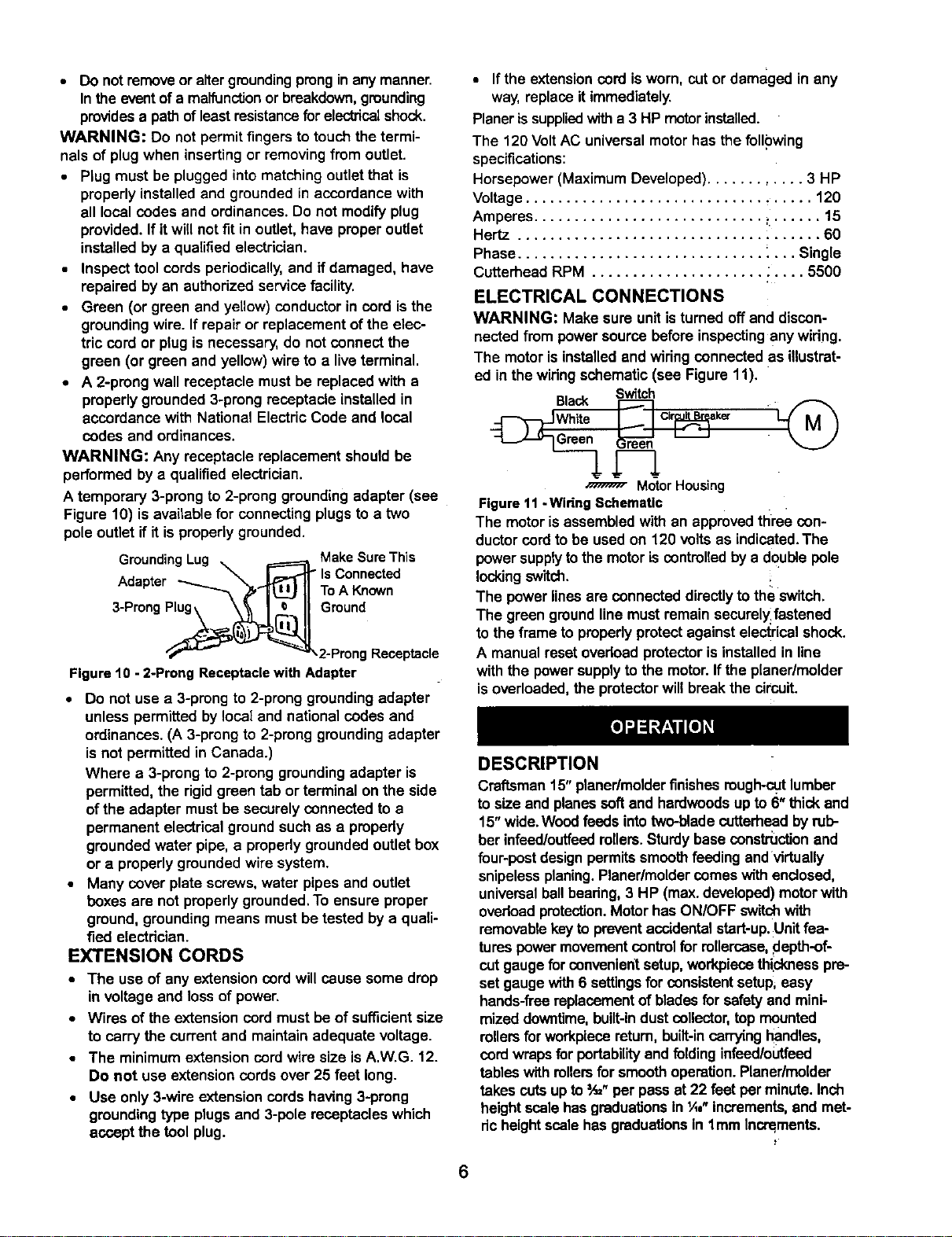
A temporary 3-prong to 2-prong grounding adapter (see
Figure 10) is available for connecting plugs to a two
pole outlet if it isproperly grounded.
GroundingLug _ r==_MakoeSUrc_e'rhis
Adapter IIToAKnown
3-ProngP__.. Ground
"_"--'- _"_2-Prong Receptacle
Figure10 - 2-ProngReceptaclewith Adapter
• Do not use a 3-prong to 2-prong groundingadapter
unless permitted by local and national codes and
ordinances.(A 3-prong to 2-prong groundingadapter
is not permittedin Canada.)
Where a 3-prongto 2-preng groundingadapter is
permitted, the rigidgreen tab or terminal on the side
of the adapter must be securely connected to a
permanent electricalground such as a propedy
groundedwater pipe, a propedy groundedoutletbox
or a properlygrounded wire system.
• Many cover plate screws, water pipes and outlet
boxes are not properlygrounded.To ensure proper
ground, groundingmeans mustbe tested by a quali-
fied electrician.
EXTENSION CORDS
• The use of any extensioncord will cause some drop
in voltage and lossof power.
• Wires of the extension cord mustbe of sufficientsize
to carry the currentand maintainadequate voltage.
• The minimumextension cord wire size isA.W.G. 12.
Do not use extension cords over 25 feet long.
• Use only 3-wire extensioncords having3-prong
groundingtype plugs and 3-pole receptacles which
accept the tool plug.
• Ifthe extensioncord is worn, cutor damaged in any
way, replaceit immediately.
Planeris suppliedwitha 3 HP motor installed.
The 120 Volt AC universalmotorhas the following
specifications:
Horsepower (Maximum Developed)............ 3 HP
Voltage................................... 120
Amperes............................ _...... 15
Hertz ..................................... 60
Phase.............................. _... Single
Cutterhead RPM ..................... : .... 5500
ELECTRICAL CONNECTIONS
WARNING: Make sure unit is turned off and discon-
nected from powersource beforeinspectingany widng.
The motor is installedand wiringconnected as illustrat-
ed in the wiring schematic (see Figure 11).
Switch
Cir k_"
MotorHousing
Figure11- WiringSchematic
The motor is assembled with an approvedthree con-
ductorcordto be used on 120 volts as indicated.The
power supplytothe motoris controlledby a double pole
locking switch. !.
The power linesare connecteddirectlyto the switch.
The green groundlinemust remainsecurel_fastened
to the frame to propedyprotectagainst electricalshock.
A manual resetovedoad protector is installedin line
with the power supplytothe motor.If the planer/molder
isoverloaded,the protectorwill break the circuit.
DESCRIPTION
Craftsman15" planer/molderfinishesrough-cutlumber
to size and planessoft and hardwoodsup to 6"thickand
15"wide.Woodfeeds intotwo-blade cutterheadbyrub-
ber infead/outfeedrollers.Sturdybase censtmcUon and
four-post designpermitssmoothfeeding andvirtually
snipelessplaning.Planer/moldercomeswithenclosed,
universalball beadng, 3 HP (max.developed)motorwith
ovedoad protection.Motorhas ON/OFF switchwith
removablekeyto preventaccidentalstart-up.Unit fea-
tures power movementcontrolfor rollercase,depth-of-
cut gauge for convenient setup,workpiecethid(ness pre-
set gauge with6 settingsfor consistentsetup,easy
hands-flea replacementof blades for safetyand mini-
mizeddowntime,built-industcollector, top mounted
rollersfor workpiecareturn, built-incarryinghandles,
cordwraps forportability and folding infeed/outfeed
tables with rollersforsmoothoperation.Planer/molder
takes cutsupto =A_"per pass at 22 feet per minute.Inch
heightscale hasgraduationsin 'A,"increments,and met-
dcheightscalehas graduationsin lmm Incrslments.
6

Table Size ............................. 15 x 16"
ExtensionTable Size .................... 15 x 11"
Base Size ............................. 32 x16"
WorkpieceWidth (max.) ...................... 15"
WorkpieceThickness (max.) ................... 6"
Maximum Depth of Cut ..................... 3/32"
Cuts Per Minute ......................... 11,000
Feed Rate........................... 11122FPM
Overall Dimensions .......... 56" H x 34" W x 40" D
Weight ................................ 150 Ibs
OPERATION SAFETY RULES
WARNING: For yourown safety, road all of the
instructionsand precautions before operating tool.
WARNING: Operation of any powertoolcan result in
foreignobjects being thrown intoeyes which can result
in severe eye damage. Always wear safety goggles
complyingwith United States ANSI Z87.1 (shown on
package) before commencing powertool operation.
CAUTION: Always observe the following safety pre-
cautions:
• Know general power tool safety. Make sure all pre-
cautions are understood (see pages 2, 3 and 7).
• Whenever adjustingor replacingany partson
planer/molder,turn switchOFF and removeplugfrom
power source.
• Make sure all guards are properlyattached and
securely fastened.
• Make sure all movingparts are free from interference.
• Always wear eye protectionor face shield.
• Make sure blades are aligned and properlyattached
to cutterhead.
• Do not plug in planer/molder unlessswitchis in off
position. After turning switchon, allow planer/molder
to come to fullspeed beforeoperating.
• Keep hands clear of all movingparts.
• Do notforce cut. Slowing or stallingwilloverheat
motor.Allow automaticfeed tofunction properly.
• Use quality lumber.Blades last longerand cuts are
smoother with good qualitywood.
• Do not plane material shorter than 17", narrower
than ¾", wider than 15" or thinner than t/8".
• Never make planing cut deeper than =/_".
• Maintain the proper relationshipsof infeedand out-
feed table surfaces and cutterhead blade path.
• Do not back the work toward the infeedtable.
• Takeprecautionsagainstkickback.Donot permit any-
one to stand or cross in line of cutterhead'srotation.
Kickbackor thrown debds willtravelin thisdirection.
• Turn switchoffand disconnect power whenever plan-
er/molder is notin use.
• Replace blades as they become damaged or dull.
• Keepplaner/molder maintained.Followmaintenance
instructions(see pages 16-16).
OPERATING CONTROLS
ON/OFF SWITCH
Refer to Figure 12.
The ON/OFF switch islocated on the front of the plan-
er/molder motor.Toturn the planar/molderON, move
the switch to the up position. To turnthe planer/molder
OFF, move the switch to the down position.
CIRCUIT BREAKER
Refer to Figure 12.
The planer/molder is equipped with a motorprotection
device-circuitbreaker.The breakerwill automatically
shut the planer/molder off when excessivecurrent is
consumed.
If the breaker is tripped, turn the planer/molderoff and
resetthe circuitby pressing the button.
CAUTION: Be sure to turn the planer/molderoff prior
to resettingthe circuitbreaker to avoid unintentional
start-upof the planer/molder.
Figure 12 - ONIOFF Switch; Circuit Breaker On Right
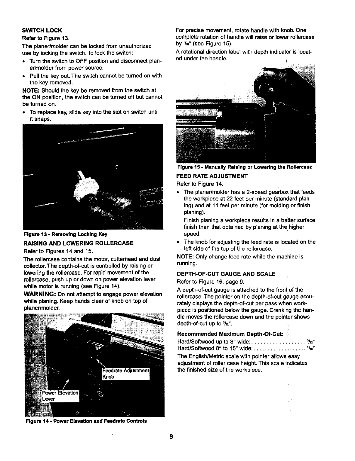
SWITCH LOCK
Refer to Figure 13.
The planer/molder can be lockedfrom unauthorized
use by lockingthe switch.To lockthe switch:
• Turn the switch to OFF positionand disconnect plan-
er/molder from power source.
• Pull the key out. The switchcannot be turned on with
the key removed.
NOTE: Should the key be removed from the switch at
the ON position,the switchcan be turned off but cannot
be turned on.
• To replace key, slide key intothe sloton switch until
itsnaps.
Figure 13 - Removing Locklng Key
RAISING AND LOWERING ROLLERCASE
Refer to Figures 14 end 15.
The rollercasecontains the motor,cutterhead and dust
collector.The depth-of-cut is controlled by raisingor
loweringthe rollercase. For rapid movementof the
rollercase, push up or down on power elevation lever
while motor is running(see Figure 14).
WARNING: Do notattempt to engage powerelevation
while planing.Keep hands clear of knob on top of
planer/molder.
For precise movement, rotate handle with knob.One
complete rotationof handle willraise or lower renercase
by 1/16"(see Figure 15).
A rotationaldirectionlabelwith depth indicatorislocat-
ed under the handle.
Figure 15 - Manually Raising or Lowering the Rollercase
FEED RATE ADJUSTMENT
Refer to Figure 14.
• The planer/molder has a 2-speed gearbox that feeds
the workpiece at 22 feet per minute(standard plan-
ing) and at 11 feet per minute(for moldingor finish
planing).
Finish planinga workpiece results in a better surface
finish than that obtained by planing at the higher
speed.
• The knob for adjustingthe feed rate is located on the
left side of the top ofthe mllercese.
NOTE: Only change feed rate while the machine is
running.
DEPTH-OF-CUT GAUGE AND SCALE
Refer to Figure 16, page 9.
A depth-of-cutgauge is attached to the front of the
rellercase.The pointeron the depth-of-cut gauge accu-
ratelydisplays the depth-of-cutper passwhen work-
piece is positioned below the gauge. Crankingthe han-
dle moves the mllercase down and the pointer shows
depth-of-cutup to 3h=".
Recommended Maximum Depth-Of-Cut:
Hard/Softwood up to 8" wide:.................. 3/_,,
Hard/Softwood 8" to 15" wide: ................... 1/_,,,
The English/Metricscale with pointerallowseasy
adjustment of roller case height.This scale indicates
the finishedsize of the workpiece.
Figure 14 - Power Elevation and Feedrate Controls
8
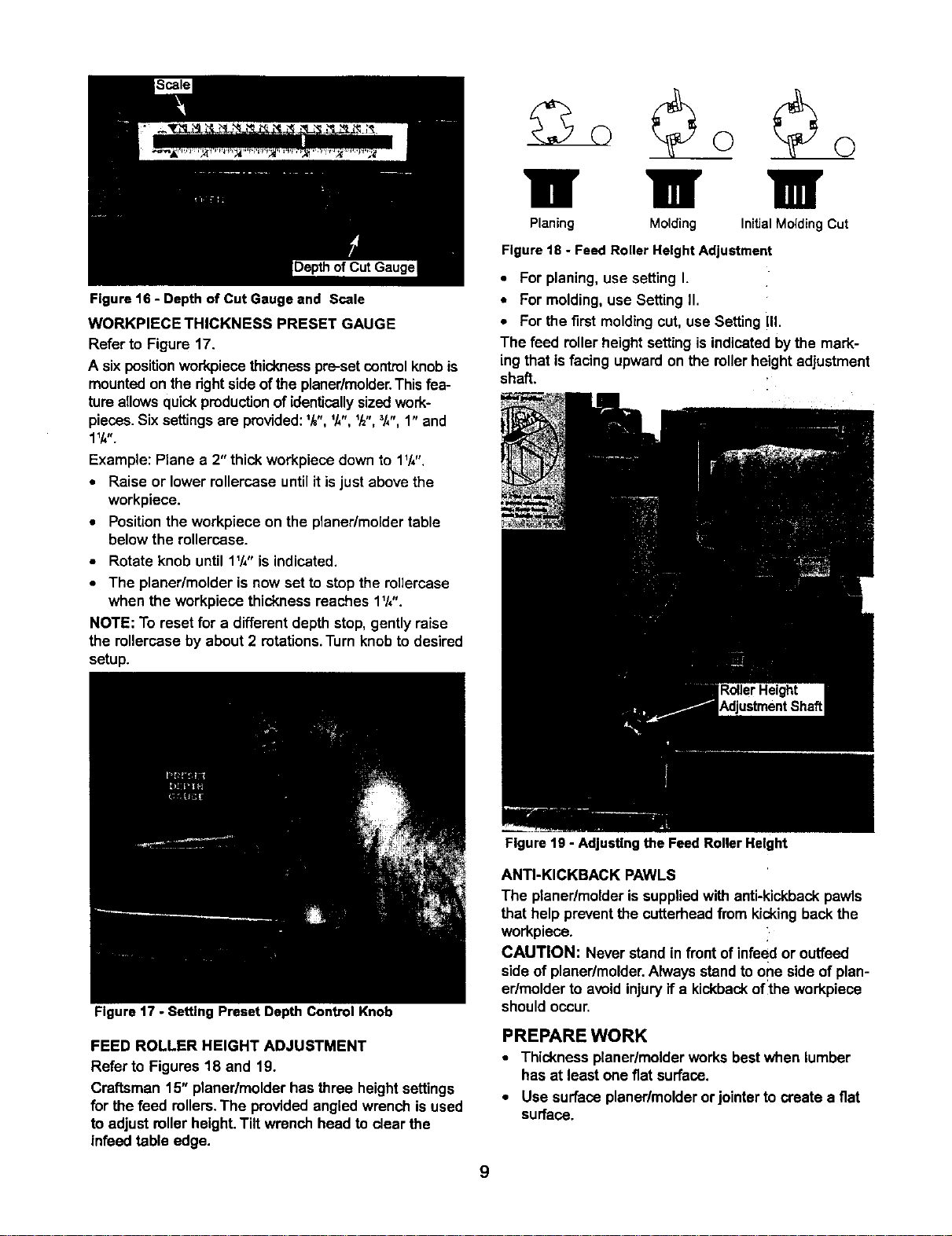
Figure16 - Depthof Cut Gauge and Scale
WORKPIECE THICKNESS PRESET GAUGE
Refer to Figure 17.
A sixpositionworkpiecethicknesspre-setcontrolknobis
mountedon the rightsideof the planer/molder. This fea-
tureallowsquick productionof identically sizedwork-
pieces.Six settingsare provided:lk", lk", _h",3k",1" and
1tk,,.
Example: Ptene a 2" thick workpiece down to 1V4".
• Raise or lower rollercese until itisjust above the
workpiece.
• Positionthe workpiece on the planer/moldertable
belowthe rollercese.
• Rotate knob until 1V,"is indicated.
• The planer/molder is now set to stop the rellercase
when the workpiecethicknessreaches 1W'.
NOTE: To reset for a differentdepth stop,gently raise
the rellercese by about 2 rotations.Turnknob to desired
setup.
111 1B /
Planing Molding InitialMolding Cut
Figure 18 - Feed Roller Height Adjustment
• For planing, use setting I.
• For molding, use Setting II.
• For the first molding cut, use Setting III.
The feed roller height setting is indicated by the mark-
ing that is facing upward on the rollerheight adjustment
shaft.
Figure 17 - Setting Preset Depth Control Knob
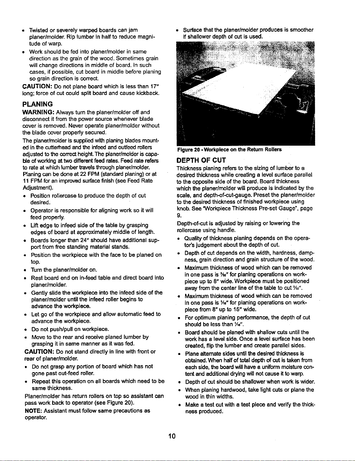
FEED ROLLER HEIGHT ADJUSTMENT
Refer to Figures 18 and 19.
Craftsman 15" planedmolder has three height settings
for the feed rollers.The provided angled wrench is used
to adjust rollerheight.Tilt wrenchhead to clear the
infeed table edge.
Figure 19 - Adjusting the Feed Roller Height
ANTI-KICKBACK PAWLS
The planer/molder issuppliedwith anti-kickbackpawls
that help prevent the cutterheadfrom kickingback the
workpiece.
CAUTION: Neverstand infront of infeedor outfeed
side of planer/molder.Alwaysstand to o_e side of plan-
er/molder to avoid injuryif a kickbackofthe workpiece
shouldoccur.
PREPARE WORK
• Thickness planer/molderworks best when lumber
has at least one fiat surface.
• Use surface planer/molderor jointerto create a fiat
surface.
9
• Twisted or severely warped boards can jam
planer/molder.Rip lumber in hall to reduce magni-
tude of warp.
• Work shouldbe fed into planer/molder in same
directionas the grainof the wood. Sometimes grain
willchange directions in middle of board. In such
cases, if possible, cut board in middle before planing
so grain direction is correct.
CAUTION: Do not plane board which is less than 17"
long; force of cut could split board and cause kickback.
PLANING
WARNING: Always turn the planer/molder off and
disconnectit from the power source whenever blade
cover is removed. Never operate planer/molderwithout
the blade cover properly secured.
The planer/molderissuppliedwith planingbladesmount-
ed in the cutterheadandthe infeedand ouffeedrollers
adjustedto the correct height.The planer/molderis capa-
ble of workingat twodifferentfeed rates.Feed rate refers
to rateat which lumber travelsthrough planer/molder.
Planingcan be done at 22 FPM (standardplaning)orat
11 FPM foran improvedsurfacefinish (see Feed Rate
Adjustment).
• Positionrollercaseto producethe depth of cut
desired.
• Operator isresponsiblefor aligningwork so it will
feed properly.
• Liftedge to infeed side of the table by grasping
edges of board at approximatelymiddle of length.
• Boards longerthan 24" should have additional sup-
port from free standingmaterial stands.
• Positionthe workpiece with the face to be planed on
top.
• Turn the planer/molder on.
• Rest board end on in-feed table and direct board into
planer/molder.
• Gently slide the workpiece intothe infeed side of the
planer/molder untilthe infeed rollerbegins to
advance the workpiece.
• Let go of the workpiece and allow automatic feed to
advance the workpiece.
• Do not push/pullon workpiece.
• Moveto the rear and receive planed lumber by
graspingit in same manner as it was fed.
CAUTION: Do not stand directlyin line with front or
rear of planer/molder.
• Do not grasp any portionof board whichhas not
gone past out-feed roller.
• Repeat this operation on all boards which need to be
same thickness.
Planer/molder has return milers on top so assistantcan
pass work back to operator (see Figure 20).
NOTE: Assistant mustfollow same precautionsas
operator.
• Surfacethatthe planer/molderproducesis smoother
if shallowerdepth of cut is used.
Figure 20 -Workplece on the Return Rollers
DEPTH OF CUT
Thickness planingrefers to the sizing of lumberto a
desired thicknesswhile creating a level surface parallel
to the oppositeside of the beard. Boardthickness
which the planer/molderwill produce is indicated by the
scale, and depth-of-cut-gauge.Preset the planer/molder
to the desiredthicknessof finishedworkpiece using
knob.See "VVorkpieceThickness Pre-set Gauge", page
9.
Depth-of-cutis adjustedby raisingor loweringthe
rollercaseusing handle.
• Qualityof thicknessplaningdepends on the opera-
tor'sjudgement aboutthe depth of cut.
• Depthof cut depends on the width, hardness,damp-
ness, grain directionand grain structureof thewood.
• Maximumthicknessof wood which can be removed
inone pass is=,_"for planingoperations on work-
piece up to 8"wide.Workpieca mustbe positioned
awayfrom the centerline ofthe table to cut3/=,,.
• Maximumthicknessof wood whichcan be removed
in one pass is _A0"for planingoperationson work-
piece from 8"up to 15"wide.
Foroptimumplaning performance, the depth of cut
shouldbe less than ¼6".
Board should be planed with shallowcuts untilthe
work has a levelside. Once a levelsurface has been
created, flipthe lumberand create parallel sides.
• Plane alternatesidesuntilthe desiredthickness is
obtained.When halloftotal depth of cut is taken from
each side,the board willhavea uniformmoisturecon-
tentand additionaldryingwillnot causeit to warp.
• Depthof cut shouldbe shallowerwhen workis wider.
• When planinghardwood, take light cuts or plane the
wood in thin widths.
Make a test cut witha test piece and verifythe thick-
ness produced.
10
• Check accuracy oftest cut prior to working on fin-
ishedproduct.
AVOID DAMAGE TO BLADES
• Thickness planer/molder is a precision woodworking
machine and should be used on qualitylumber only.
• Do not plane dirty boards;dirt and small stonesare
abrasive and wear out blade.
• Removenails and staples.Use planer/molderto cut
woodonly.
• Avoid knots. Heavily cross-grained wood makes
knots hard. Knots can come loose and jam blade.
CAUTION: Any article that encountersplaner/molder
bladesmay be forciblyejectedfrom planer/moldercreat-
ingdsk of injury.
AVOIDING SNIPE
• Snipe refersto e depression at either end of board
caused by an unevenforce on cutterheadwhen
work is entering or leaving planer/molder.
• Snipe occurswhen boards are not supportedprop-
erly or when only one feed roller is in contact with
work at beginningor end of cut.
• To avoid snipe on the lead edge of the workpiece,
adjustthe infeedtable up slightlyabove hodzontaL
• To avoid snipe on the trailingedge of the workpiece,
adjustthe ouffeed table up slightlyabove horizontal.
• When planing more than one board ofthe same
thickness, butt boardstogether to avoidsnipe.
• Snipe is more apparent when deeper cuts are taken.
• Feedwork in direction of grain.Work fed against
grain will have chipped, splintered edges.
MOLDING
Molding, also known as millworkor trim, can be defined
as a stripof wood milledwith a plain or decorativesur-
face which is continuous throughoutitslength.
• Toget superiormoldingfinish, workpieca mustbe
planed and presized pdor to molding.Always presize
the workpieca to within ',_,"of the final thickness
priorto molding.
• During moldingoperation, do not exceed I/,, total
depth of cut.
Certain molding profilesrequireouter edge clean-up.
When using such profilesthe workpieca must be pre-
sized to t_,,larger than the final width.This willallow '1,,"
for clean-up on either side.
Certain moldingprofilescut onlythe edge of workpieca.
When using such profilesworkpieca must be presized
to the same widthas the final width.
are 'k" thickand are installed using the moldinggibs
and lk" spacers providedwith the planer/molder.
The cutterhead on this planer/molderhas four slots.
Two slotsare used to hold the planing blades.The
other two slots are used to hold moldingcuttersand
pattern knives.The settingblockin the slot alignsthe
cuttersso that both cutterscut the workpiece in the
same positionprovidingprecise cutsand improved sur-
face finish.
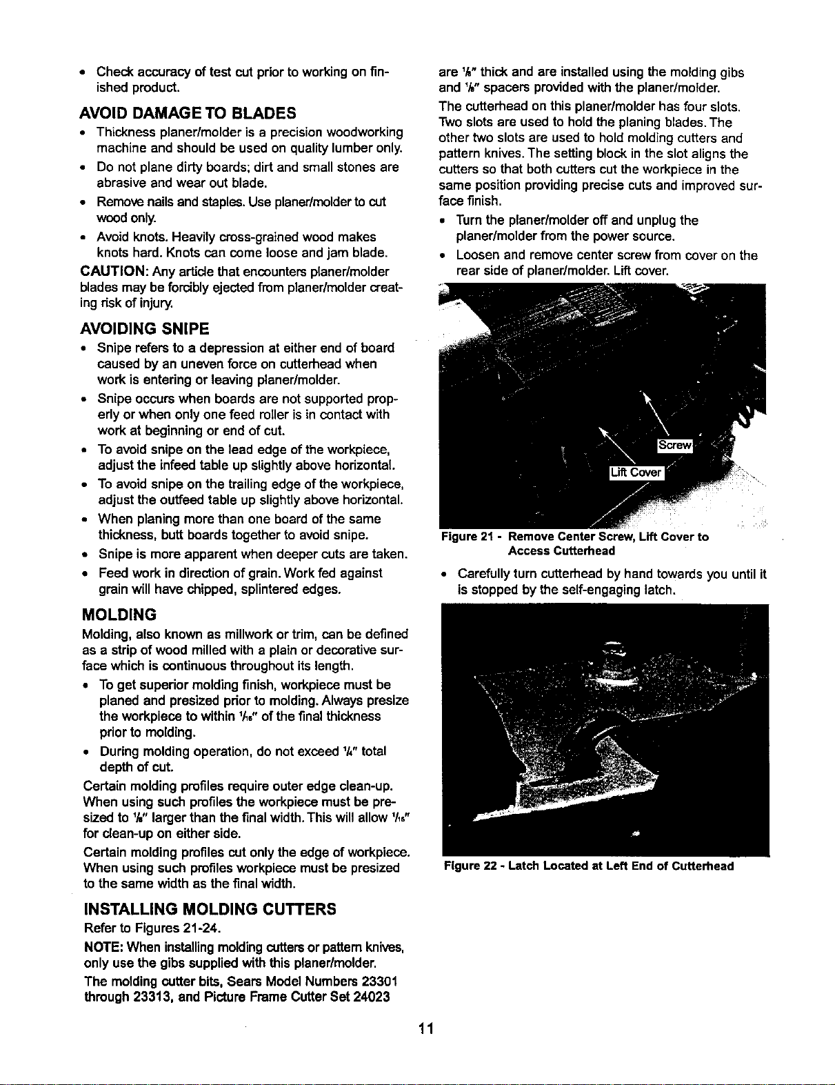
• Turn the planer/molderoff and unplugthe
planer/molderfrom the power source.
• Loosenand removecenter screw from cover on the
rear side of planer/molder.Lif_cover.
Figure 21 - Remove Center Screw, Lift Cover to
Access Cutterhead
• Carefully turn cutterheadby hand towards you until it
is stopped by the self-engaging latch.
Figure 22 - Latch Located at Left End of Cutterhead
INSTALLING MOLDING CUTTERS
Refer to Figures 21-24.
NOTE: When installingmoldingcuttersor pattamknives,
only use the gibssupplied with this planer/molder.
The moldingcutter bits, Sears Model Numbers 23301
through 23313, and Picture Frame Cutter Set 24023
11
Ifthe slotfacing you containsthe blade, depress the
red latch at the left hand side of the cutterhead, and
carefully rotate it towardsuntilit stops at the slot with
setting block.
Be sure the slot is clean and free of any dirt, chips
or debris.
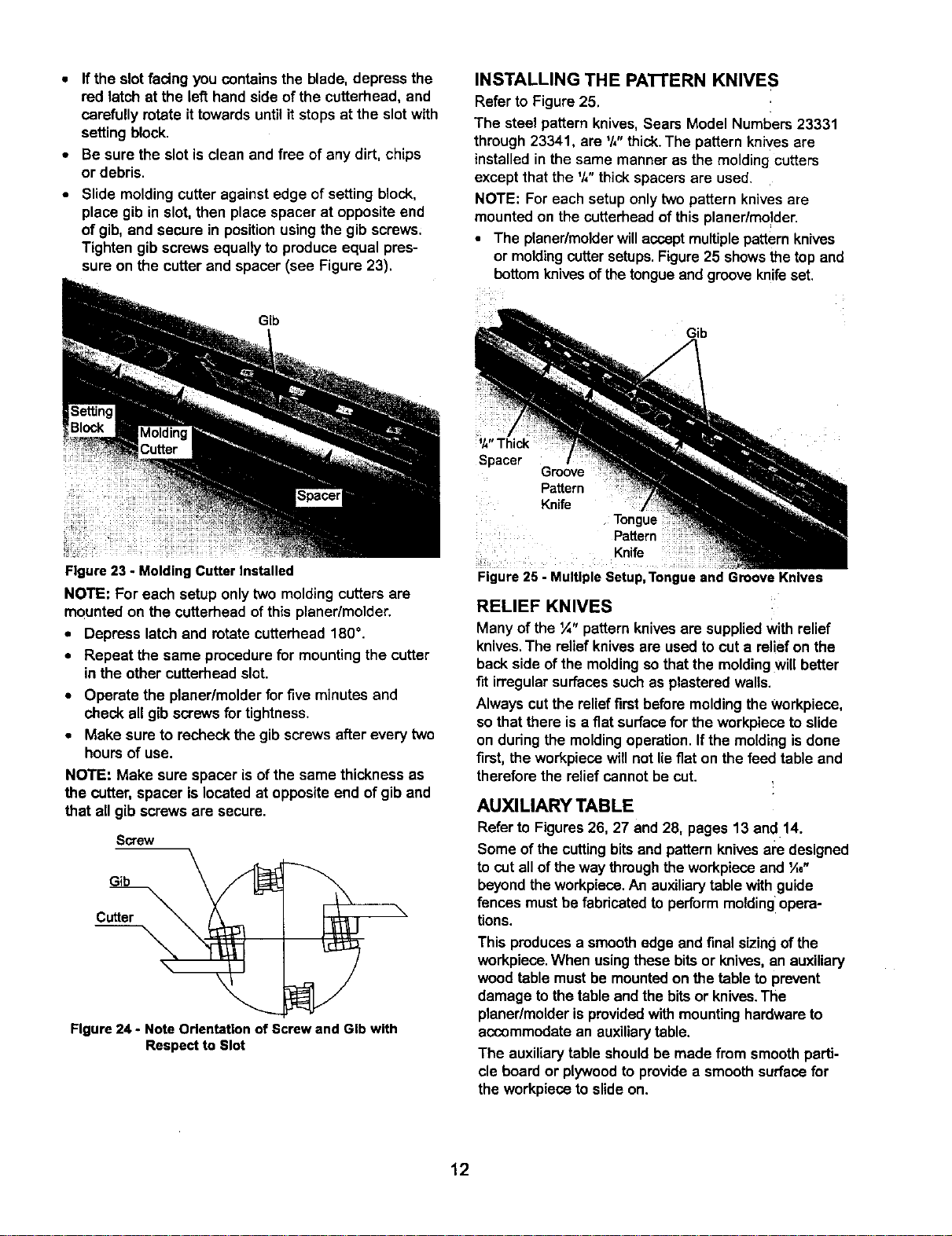
Slide molding cutter against edge of setting block,
place gib in slot, then place spacer at opposite end
of gib, and secure in position using the gib screws;
Tighten gib screws equally to produce equal pres-
sure on the cutter and spacer (see Figure 23).
Figure23 - MoldingCutterInstalled
NOTE: For each setup only two molding cutters are
mounted on the cutterhead of this planer/molder.
• Depress latch and rotate cutterhead 180=.
• Repeat the same procedurefor mountingthe cutter
in the other cutterhead slot.
• Operate the planer/molderfor five minutes and
check all gibscrews fortightness.
• Make sure to recheckthe gib screws after every two
hoursof use.
NOTE: Make sure spacer is ofthe same thicknessas
the cutter, spacer is located at oppositeend of gib and
that all gib screws are secure.
Screw
Gib
Cutter
Figure 24 - Note Odentatlon of Screw and GIb with
Respect to Slot
INSTALLING THE PA'I-rERN KNIVES
Refer to Figure 25.
The steel patternknives, Sears Model Numbers 23331
through 23341, are '/," thick.The patternknives ere
installedin the same manneras the molding cutters
except that the '/,"thick spacersare used.
NOTE: For each setup onlytwo pattern knivesare
mounted on the cutterheadof this planer/mo!der.
• The planer/molderwillacoept multiple pattern knives
or moldingcuttersetups.Figure 25 showsthe topand
bottomknivesofthe tongueand grooveknifeset.
Gib
1/4"Thick
Spacer /
Figure 25 - Multiple Setup, Tongue and Groove Knives
Groove
Pattern
Knife
Tongue
Pattern
Knife
RELIEF KNIVES
Many of the ¼" pattern knivesare supplied with relief
knives,The reliefknives are usedtocut a relief on the
backside of the moldingso that the moldingwill better
fit irregular surfacessuch as plasteredwalls.
Always cut the relief first before molding the workpieca,
so that there is a fiat surface for the workpieca to slide
on during the molding operation. If the molding is done
first, the workpiece will not lie fiat on the feed table and
therefore the relief cannot be cut.
AUXILIARY TABLE
Refer to Figures26, 27 and 28, pages 13 and 14.
Some of the cuttingbitsand pattern knivesam designed
to cut all of the way through the workpiece and '/,e"
beyondthe workpieca.An auxiliarytable withguide
fences mustbe fabdcated to perform moldingIopera-
tions.
This produces a smoothedge and finalsizingofthe
workpiece.When usingthese bits or knives,an auxiliary
wood table mustbe mountedon the table to prevent
damage to the table and the bitsor knives.The
planer/molderis providedwithmountinghardwareto
accommodatean auxiliarytable.
The auxiliary table shouldbe made fromsmoothparti-
cle board or plywoodto providea smooth surfacefor
the workpieceto slide on.
12
GUIDE FENCES
When molding,the workpiece must be guided intothe
molding cutter bits or knives properlyin order to pro-
duce the desired shape and size molding.Usingprop-
edy adjusted guide fences assures the workpiecepass-
es the molding cutters/knivesin the same position
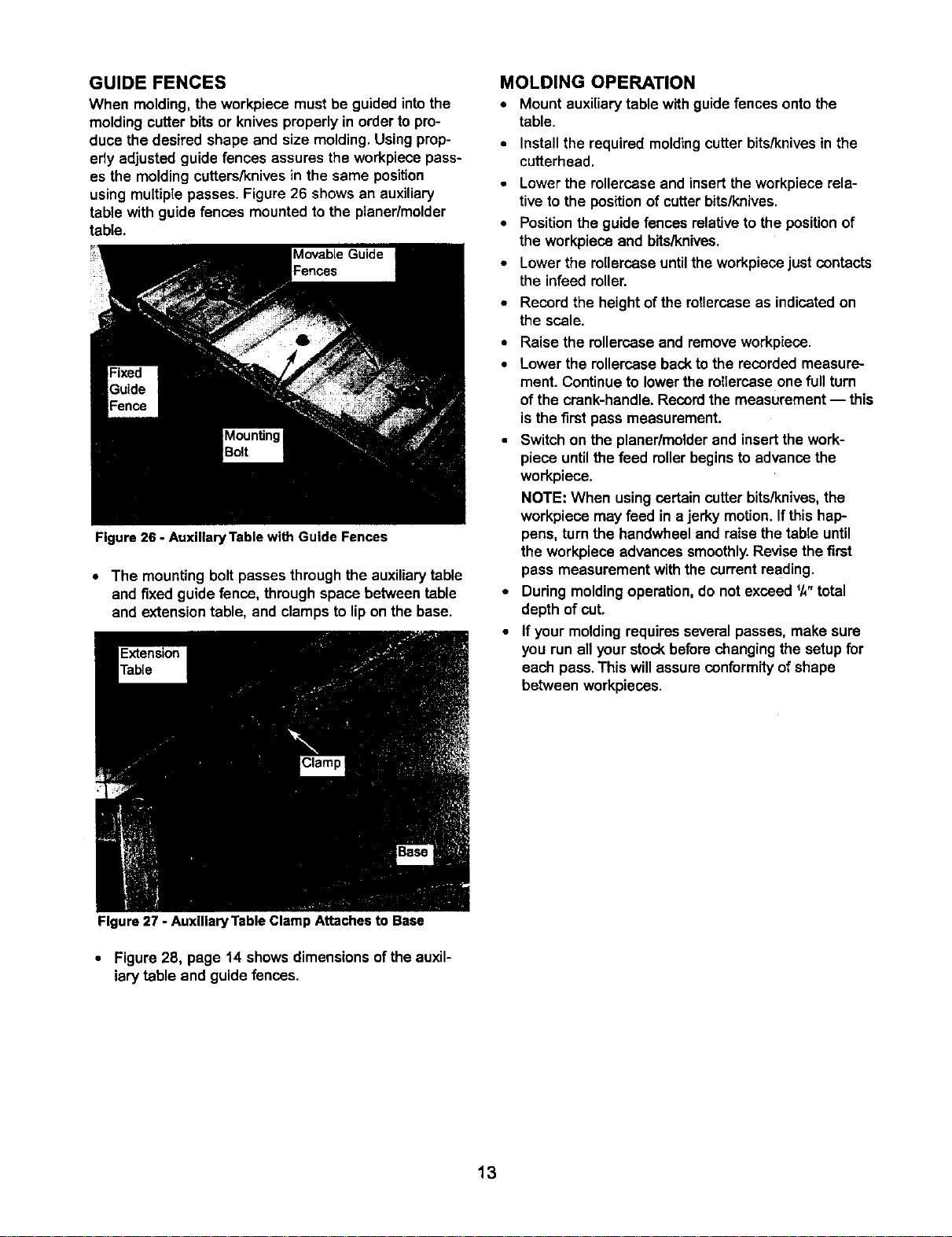
using multiple passes. Figure 26 shows an auxiliary
table with guide fences mounted to the planer/molder
table.
Figure 26 - AuxlliaryTable with Guide Fences
• The mounting boltpasses through the auxiliarytable
and fixed guide fence, through space between table
and extensiontable, and clamps to lipon the base.
MOLDING OPERATION
• Mount auxiliarytable withguide fences ontothe
table.
• Install the required moldingcutter bits/knives in the
cutterhead.
• Lower the rollercaseand insert the workpiecerela-
tiveto the positionof cutter bits/knivas.
• Positionthe guide fencesrelativeto the positionof
the workpiece and bits/knives.
• Lower the rollercaseuntilthe workpiecejust contacts
the infeedroller.
• Record the height of the rollercaseas indicatedon
the scale.
• Raisethe rellercase and removeworkpiece.
• Lower the rollercasebacktothe recordedmeasure-
ment. Continueto lowerthe rollercaseone full turn
of the crank-handle.Recordthe measurement -- this
isthe first pass measurement.
• Switchon the planer/molderand insertthe work-
piece untilthe feed rollerbegins toadvance the
workpiece.
NOTE: When usingcertain cutterbits/knives,the
workpiece may feed in a jerky motion. If this hap-
pens, turnthe bandwheel and raise the table until
the workpiece advances smoothly.Revise the first
pass measurement with the current reading.
• During moldingoperation, do not exceed I/," total
depth of cut.
• If your moldingrequiresseveral passes,make sure
you run all yourstockbeforechangingthe setup for
each pass.This will assure conformity of shape
between workpieces.
Figure 27 - Auxiliary Table Clamp Attaches to Base
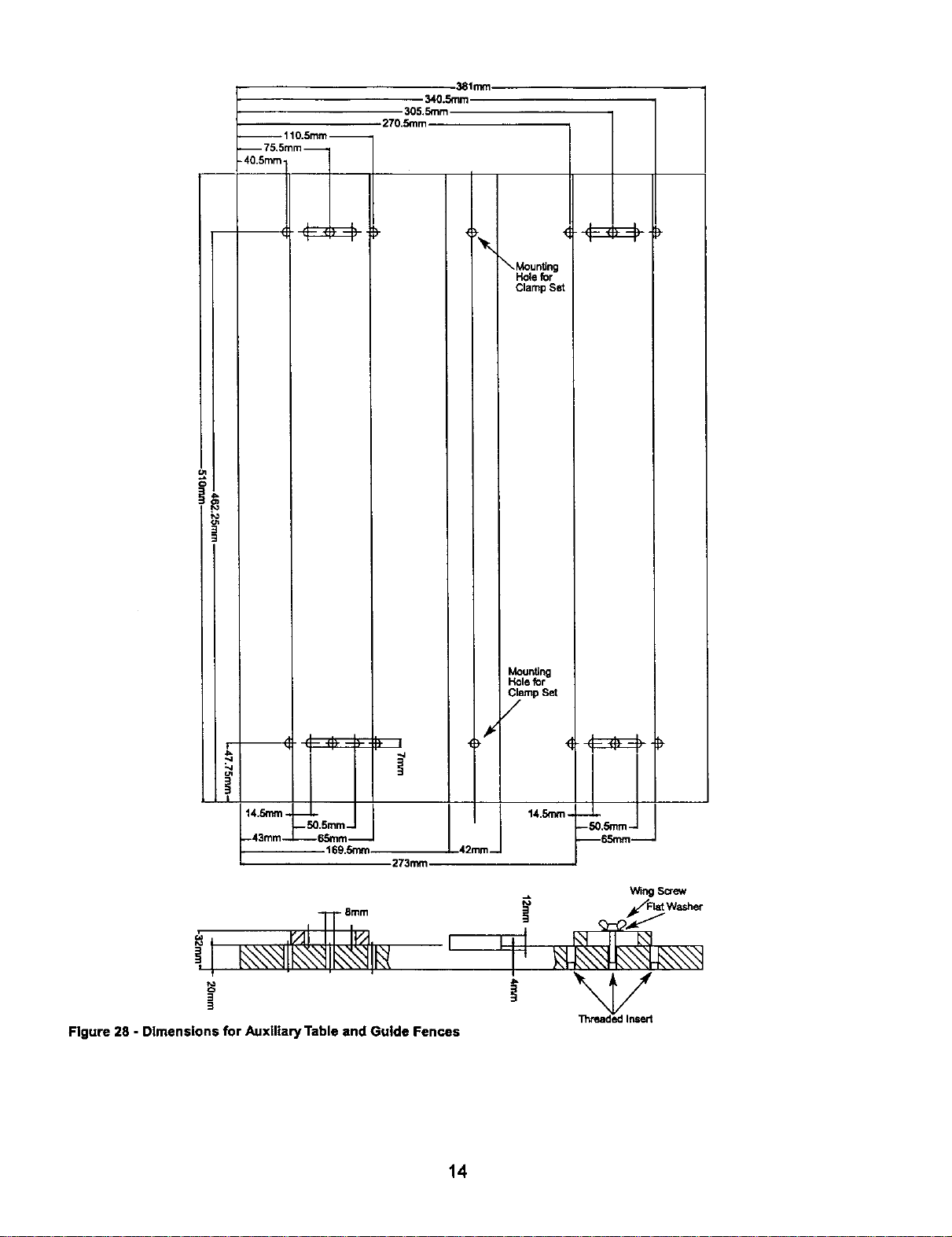
• Figure 28, page 14shows dimensionsof the auxil-
iary table and guide fences.
13
110.Smm--
75,5mm
305.5mm
270.5mm
38tmm
340.5mm
Mounting
I
I
• I
-4
-43ram-- -- 6.Smm--
1
169.5mm
273mm,
Ll;'im
3
Figure 28 - Dimensions for Auxiliary Table and Guide Fences
Mounting
Hole _r
Clamp Set
/
J
42 m_ 14.Smrn.
Wing Screw
Flat Washer
!
i
14
 Loading...