

Craftsman 351217330 Owner’s Manual

Operator's Manual
CRRFT$14RN
13"
PLANER/MOLDER
Model No.
351.21 7330
CAUTION: Read and follow
all Safety Rules and Operating
Instructions before First Use
of this Product.
Sears, Roebuck and Co., Hoffman Estates, IL 60179 U.S.A.
www.sears.com/craftsman
17509.02 Draft (08/31/01 )
Warranty.................................... 2
SafetyRules............................... 2-3
Unpacking.................................. 3
Assembly................................. 3-4
Installation................................. 4-5
Operation................................ 5-13
Maintenance............................. 13-14
Troubleshooting............................. 15
PartsIllustrationandList................... 16-21
Espa_ol................................. 23-36
FULL ONE YEAR WARRANTY
If this product fails due to a defect in material or work-
manship within one year from the date of purchase,
Sears will at its option repair or replace it free of
charge. Contact your nearest Sears Service Center
(1-800-4-MY-HOME) to arrange for product repair, or
return this product to place of purchase for replacement.
If this product is used for commercial or rental purposes,
this warranty will apply for 90 days from the date of
purchase.
This warranty applies only while this product is used in
the United States.
This warranty gives you specific legal rights and you may
also have other rights which vary from state to state.
Sears, Roebuck and Co., Dept. 817WA, Hoffman
Estates, IL 60179
WARNING: For your own safety, read all of the
instructions and precautions before operating tool.
CAUTION: Always follow proper operating procedures
as defined in this manual even if you are familiar with
use of this or similar tools. Remember that being care-
less for even a fraction of a second can result in severe
personal injury.
BE PREPARED FOR JOB
• Wear proper apparel. Do not wear loose clothing,
gloves, neckties, rings, bracelets or other jewelry
which may get caught in moving parts of machine.
• Wear protective hair covering to contain long hair.
• Wear safety shoes with non-slip soles.
• Wear safety glasses complying with United States
ANSI Z87.1. Everyday glasses have only impact
resistant lenses. They are NOT safety glasses.
• Wear face mask or dust mask if operation is dusty.
• Be alert and think clearly. Never operate power tools
when tired, intoxicated or when taking medications
that cause drowsiness.
© Sears, Roebuck and Co.
PREPARE WORK AREA FOR JOB
• Keep work area clean. Cluttered work areas invite
accidents.
• Do not use power tools in dangerous environments.
Do not use power tools in damp or wet locations. Do
not expose power tools to rain.
• Work area should be properly lighted.
• Proper electrical receptacle should be available for
tool. Three prong plug should be plugged directly
into properly grounded, three-prong receptacle.
• Extension cords should have a grounding prong and
the three wires of the extension cord should be of
the correct gauge.
• Keep visitors at a safe distance from work area.
• Keep children out of workplace. Make workshop child-
proof. Use padlocks, master switches or remove switch
keys to prevent any unintentional use of power tools.
TOOL SHOULD BE MAINTAINED
• Always unplug tool prior to inspection.
• Consult manual for specific maintaining and adjust-
ing procedures.
• Keep tool lubricated and clean for safest operation.
• Remove adjusting tools. Form habit of checking to
see that adjusting tools are removed before switch-
ing machine on.
• Keep all parts in working order. Check to determine
that the guard or other parts will operate properly
and perform their intended function.
• Check for damaged parts. Check for alignment of
moving parts, binding, breakage, mounting and any
other condition that may affect a tool's operation.
• A guard or other part that is damaged should be
properly repaired or replaced. Do not perform
makeshift repairs. (Use parts list provided to order
replacement parts.)
KNOW HOW TO USE TOOL
• Use right tool for job. Do not force tool or attachment
to do a job for which it was not designed.
• Disconnect tool when changing blades.
• Avoid accidental start-up. Make sure that the switch
is in the "off" position before plugging in.
• Do not force tool. It will work most efficiently at the
rate for which it was designed.
• Keep hands away from moving parts and cutting
surfaces.
• Never leave tool running unattended. Turn the power
off and do not leave tool until it comes to a complete
stop.
• Do not overreach. Keep proper footing and balance.
• Never stand on tool. Serious injury could occur if tool is
tipped or if blade is unintentionally contacted.
• Know your tool. Learn the tool's operation, applica-
tion and specific limitations.
2
• Use recommended accessories (refer to page 21).
Use of improper accessories may cause risk of
injury to persons.
• Handle workpiece correctly. Protect hands from pos-
sible injury.
• Turn machine off if it jams. Blade or bit jams when it
digs too deeply into workpiece. (Motor force keeps it
stuck in the work.)
• Always keep drive, cutterhead and blade guards in
place and in proper operating condition.
• Feed work into blade or cutter against direction of
rotation.
CAUTION: Think safety! Safety is a combination of
operator common sense and alertness at all times
when tool is being used.
WARNING: Do not attempt to operate tool until it is
completely assembled according to the instructions.
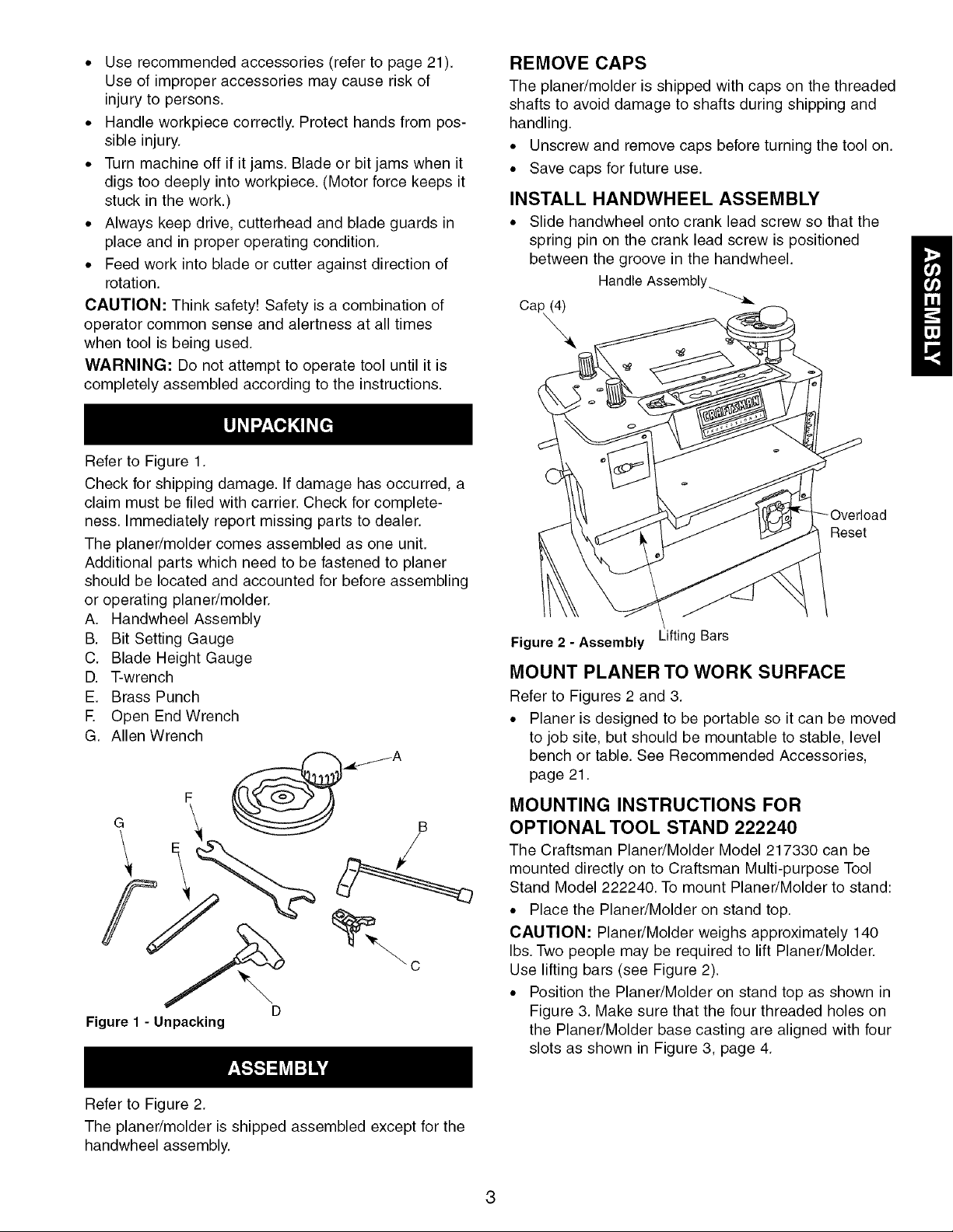
Refer to Figure 1.
Check for shipping damage. If damage has occurred, a
claim must be filed with carrier. Check for complete-
ness. Immediately report missing parts to dealer.
The planer/molder comes assembled as one unit.
Additional parts which need to be fastened to planer
should be located and accounted for before assembling
or operating planer/molder.
A. Handwheel Assembly
B. Bit Setting Gauge
C. Blade Height Gauge
D. T-wrench
E. Brass Punch
E Open End Wrench
G. Allen Wrench
F __A
G E "_ %_ /
[3
Figure 1 - Unpacking
REMOVE CAPS
The planer/molder is shipped with caps on the threaded
shafts to avoid damage to shafts during shipping and
handling.
• Unscrew and remove caps before turning the tool on.
• Save caps for future use.
INSTALL HANDWHEEL ASSEMBLY
• Slide handwheel onto crank lead screw so that the
spring pin on the crank lead screw is positioned
between the groove in the handwheel.
Handle Assembly............._
OapQ
Reset
Figure 2 - Assembly Lifting Bars
MOUNT PLANER TO WORK SURFACE
Refer to Figures 2 and 3.
• Planer is designed to be portable so it can be moved
to job site, but should be mountable to stable, level
bench or table. See Recommended Accessories,
page 21.
MOUNTING INSTRUCTIONS FOR
OPTIONAL TOOL STAND 222240
The Craftsman Planer/Molder Model 217330 can be
mounted directly on to Craftsman Multi-purpose Tool
Stand Model 222240. To mount Planer/Molder to stand:
• Place the Planer/Molder on stand top.
CAUTION: Planer/Molder weighs approximately 140
Ibs. Two people may be required to lift Planer/Molder.
Use lifting bars (see Figure 2).
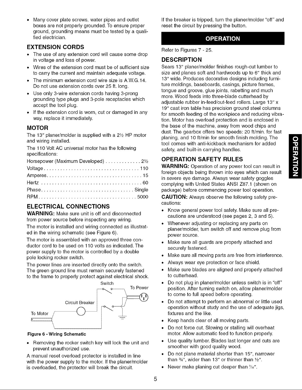
• Position the Planer/Molder on stand top as shown in
Figure 3. Make sure that the four threaded holes on
the Planer/Molder base casting are aligned with four
slots as shown in Figure 3, page 4.
Refer to Figure 2.
The planer/molder is shipped assembled except for the
handwheel assembly.
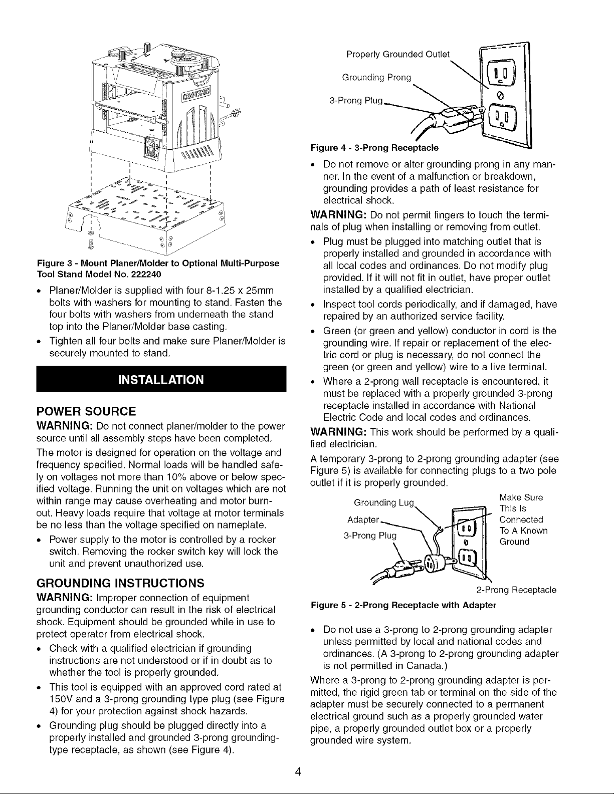
Figure 3 - Mount Planer/Molder to Optional Multi-Purpose
Tool Stand Model No. 222240
• Planer/Molder is supplied with four 8-1.25 x 25mm
bolts with washers for mounting to stand. Fasten the
four bolts with washers from underneath the stand
top into the Planer/Molder base casting.
• Tighten all four bolts and make sure Planer/Molder is
securely mounted to stand.
POWER SOURCE
WARNING: Do not connect planer/molder to the power
source until all assembly steps have been completed.
The motor is designed for operation on the voltage and
frequency specified. Normal loads will be handled safe-
ly on voltages not more than 10% above or below spec-
ified voltage. Running the unit on voltages which are not
within range may cause overheating and motor burn-
out. Heavy loads require that voltage at motor terminals
be no less than the voltage specified on nameplate.
• Power supply to the motor is controlled by a rocker
switch. Removing the rocker switch key will lock the
unit and prevent unauthorized use.
GROUNDING INSTRUCTIONS
WARNING: Improper connection of equipment
grounding conductor can result in the risk of electrical
shock. Equipment should be grounded while in use to
protect operator from electrical shock.
• Check with a qualified electrician if grounding
instructions are not understood or if in doubt as to
whether the tool is properly grounded.
• This tool is equipped with an approved cord rated at
150V and a 3-prong grounding type plug (see Figure
4) for your protection against shock hazards.
• Grounding plug should be plugged directly into a
properly installed and grounded 3-prong grounding-
type receptacle, as shown (see Figure 4).
Properly Grounded Outlet
Grounding Prong
3-Prong
Figure4 - 3-Prong Receptacle
• Do not remove or alter grounding prong in any man-
ner. In the event of a malfunction or breakdown,
grounding provides a path of least resistance for
electrical shock.
WARNING: Do not permit fingers to touch the termi-
nals of plug when installing or removing from outlet.
• Plug must be plugged into matching outlet that is
properly installed and grounded in accordance with
all local codes and ordinances. Do not modify plug
provided. If it will not fit in outlet, have proper outlet
installed by a qualified electrician.
• Inspect tool cords periodically, and if damaged, have
repaired by an authorized service facility.
• Green (or green and yellow) conductor in cord is the
grounding wire. If repair or replacement of the elec-
tric cord or plug is necessary, do not connect the
green (or green and yellow) wire to a live terminal.
• Where a 2-prong wall receptacle is encountered, it
must be replaced with a properly grounded 3-prong
receptacle installed in accordance with National
Electric Code and local codes and ordinances.
WARNING: This work should be performed by a quali-
fied electrician.
A temporary 3-prong to 2-prong grounding adapter (see
Figure 5) is available for connecting plugs to a two pole
outlet if it is properly grounded.
Make Sure
Grounding Lug_ _ This Is
Adapter_"_._ Connected
3-Pron . . TOGroundAKnown
2-Prong Receptacle
Figure 5 - 2-Prong Receptacle with Adapter
• Do not use a 3-prong to 2-prong grounding adapter
unless permitted by local and national codes and
ordinances. (A 3-prong to 2-prong grounding adapter
is not permitted in Canada.)
Where a 3-prong to 2-prong grounding adapter is per-
mitted, the rigid green tab or terminal on the side of the
adapter must be securely connected to a permanent
electrical ground such as a properly grounded water
pipe, a properly grounded outlet box or a properly
grounded wire system.
4
• If the breaker is tripped, turn the planer/molder "off" and
Many cover plate screws, water pipes and outlet
boxes are not properly grounded. To ensure proper
ground, grounding means must be tested by a quali-
fied electrician.
reset the circuit by pressing the button.
EXTENSION CORDS
• The use of any extension cord will cause some drop
in voltage and loss of power.
• Wires of the extension cord must be of sufficient size
to carry the current and maintain adequate voltage.
• The minimum extension cord wire size is A.W.G.14.
Do not use extension cords over 25 ft. long.
• Use only 3-wire extension cords having 3-prong
grounding type plugs and 3-pole receptacles which
accept the tool plug.
• If the extension cord is worn, cut or damaged in any
way, replace it immediately.
MOTOR
The 13" planer/molder is supplied with a 2Y2HP motor
and wiring installed.
The 110 Volt AC universal motor has the following
specifications:
Horsepower (Maximum Developed) ............. 2Y2
Voltage ................................... 110
Amperes ................................... 15
Hertz ..................................... 60
Phase .................................. Single
RPM .................................... 5000
ELECTRICAL CONNECTIONS
WARNING: Make sure unit is off and disconnected
from power source before inspecting any wiring.
The motor is installed and wiring connected as illustrat-
ed in the wiring schematic (see Figure 6).
The motor is assembled with an approved three con-
ductor cord to be used on 110 volts as indicated. The
power supply to the motor is controlled by a double
pole locking rocker switch.
The power lines are inserted directly onto the switch.
The green ground line must remain securely fastened
to the frame to properly protect against electrical shock.
Switch
Circuit_Breaker --__
To Motor
E
Figure6 - Wiring Schematic
• Removing the rocker switch key will lock the unit and
prevent unauthorized use.
A manual reset overload protector is installed in line
with the power supply to the motor. If the planer/molder
is overloaded, the protector will break the circuit.
Refer to Figures 7 - 25.
DESCRIPTION
Sears 13" planer/molder finishes rough-cut lumber to
size and planes soft and hardwoods up to 6" thick and
13" wide. Produces decorative designs including furni-
ture moldings, baseboards, casings, picture frames,
tongue and groove, glue joints, rabetting and much
more. Wood feeds into three-blade cutterhead by
adjustable rubber in-feed/out-feed rollers. Large 13"x
19" cast iron table has precision ground steel columns
for smooth feeding of the workpiece and reducing vibra-
tion. Motor has overload protection and is enclosed in
the base of the machine, away from wood chips and
dust. The gearbox offers two speeds: 20 ft/min, for fast
planing, and 10 ft/min for smooth finish molding. The
tool comes with anti-kickback mechanism for added
safety, and built-in carrying handles.
OPERATION SAFETY RULES
WARNING: Operation of any power tool can result in
foreign objects being thrown into eyes which can result
in severe eye damage. Always wear safety goggles
complying with United States ANSI Z87.1 (shown on
package) before commencing power tool operation.
CAUTION: Always observe the following safety pre-
cautions:
• Know general power tool safety. Make sure all pre-
cautions are understood (see pages 2, 3 and 5).
• Whenever adjusting or replacing any parts on
planer/molder, turn switch off and remove plug from
power source.
• Make sure all guards are properly attached and
securely fastened.
• Make sure all moving parts are free from interference.
• Always wear eye protection or face shield.
• Make sure blades are aligned and properly attached
to cutterhead.
• Do not plug in planer/molder unless switch is in "off"
position. After turning switch on, allow planer/molder
to come to full speed before operating.
• Do not attempt to perform an abnormal or little used
operation without study and the use of adequate jigs,
fixtures and the like.
• Keep hands clear of all moving parts.
• Do not force cut. Slowing or stalling will overheat
motor. Allow automatic feed to function properly.
• Use quality lumber. Blades last longer and cuts are
smoother with good quality wood.
• Do not plane material shorter than 15", narrower
than 3A",wider than 13" or thinner than 1/2".
• Never make planing cut deeper than %2".
• Maintaintheproperrelationshipsofinfeedandout-
feedtablesurfacesandcutterheadbladepath.
• Donotbacktheworktowardtheinfeedtable.
• Takeprecautionsagainstkickback.Donotpermit
anyonetostandorcrossinlineofcutterhead'srota-
tion.Kickbackorthrowndebriswilltravelinthis
direction.
• Turnswitchoffanddisconnectpowerwhenever
planer/molderisnotinuse.
• Replaceorsharpenbladesastheybecomedam-
agedordull.
• Keepplaner/moldermaintained.Followmaintenance
instructions(seepage13).
DEPTH OF CUT
• Thickness planing refers to the sizing of lumber to a
desired thickness while creating a level surface par-
allel to the opposite side of the board.
• Quality of thickness planing depends on the opera-
tor's judgement about the depth of cut. Depth of cut
depends on the width, hardness, dampness, grain
direction and grain structure of the wood.
• Maximum thickness of wood which can be removed
in one pass is %2"for planing operations. For opti-
mum planing performance, the depth of cut should
be less than V,6".During molding operation, do not
exceed '/4"total depth of cut.
• Board should be planed with shallow cuts until the
work has a level side. Once level surface has been
created, flip the lumber and create parallel sides.
Plane alternate sides until the desired thickness is
obtained.
• When half of total depth of cut is taken from each
side, the board will have a uniform moisture content
and additional drying will not cause it to warp.
• Depth of cut should be shallower when work is wider.
• When planing hardwood, take light cuts or plane the
wood in thin widths.
• Make test cut when working with a new type of
board or different kind of operation.
• Check accuracy of test cut prior to working on fin-
ished product.
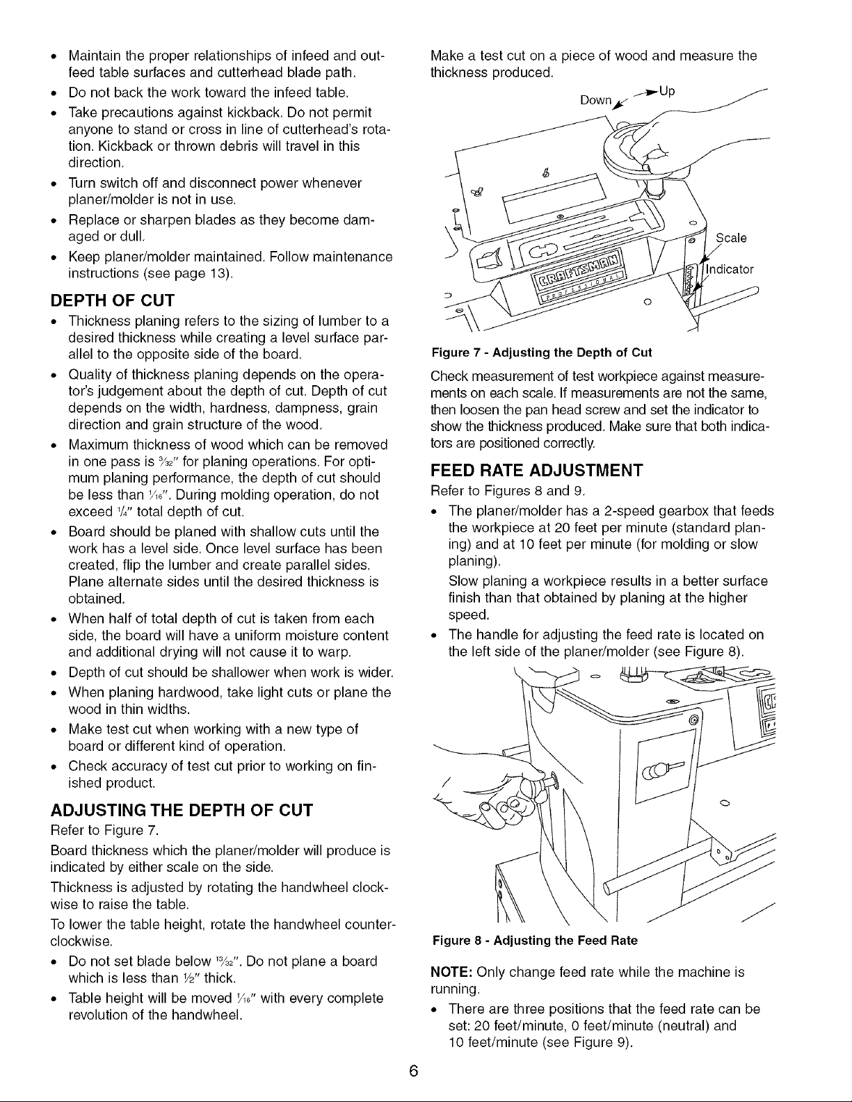
Make a test cut on a piece of wood and measure the
thickness produced.
_,.-Up
Down_
Scale
Figure 7 - Adjusting the Depth of Cut
Check measurement of test workpiece against measure-
ments on each scale. If measurements are not the same,
then loosen the pan head screw and set the indicator to
show the thickness produced. Make sure that both indica-
tors are positioned correctly.
FEED RATE ADJUSTMENT
Refer to Figures 8 and 9.
• The planer/molder has a 2-speed gearbox that feeds
the workpiece at 20 feet per minute (standard plan-
ing) and at 10 feet per minute (for molding or slow
planing).
Slow planing a workpiece results in a better surface
finish than that obtained by planing at the higher
speed.
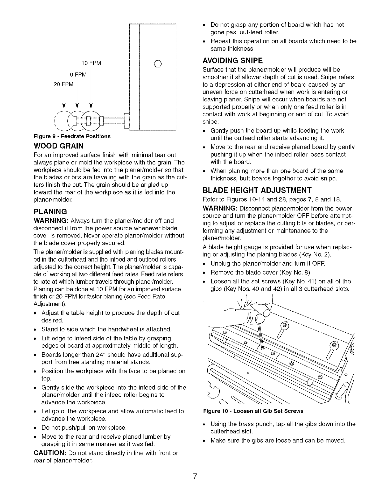
• The handle for adjusting the feed rate is located on
the left side of the planer/molder (see Figure 8).
/
ADJUSTING THE DEPTH OF CUT
Refer to Figure 7.
Board thickness which the planer/molder will produce is
indicated by either scale on the side.
Thickness is adjusted by rotating the handwheel clock-
wise to raise the table.
To lower the table height, rotate the handwheel counter-
clockwise.
• Do not set blade below %2". Do not plane a board
which is less than W' thick.
• Table height will be moved '_6" with every complete
revolution of the handwheel.
Figure 8 - Adjusting the Feed Rate
NOTE: Only change feed rate while the machine is
running.
• There are three positions that the feed rate can be
set: 20 feet/minute, 0 feet/minute (neutral) and
10 feet/minute (see Figure 9).
6
• Do not grasp any portion of board which has not
gone past out-feed roller.
• Repeat this operation on all boards which need to be
same thickness.
10 FPM
0 FPM
20 FPM
Figure9 - Feedrate Positions
WOOD GRAIN
For an improved surface finish with minimal tear out,
always plane or mold the workpiece with the grain. The
workpiece should be fed into the planer/molder so that
the blades or bits are traveling with the grain as the cut-
ters finish the cut. The grain should be angled up
toward the rear of the workpiece as it is fed into the
planer/molder.
PLANING
WARNING: Always turn the planer/molder off and
disconnect it from the power source whenever blade
cover is removed. Never operate planer/molder without
the blade cover properly secured.
The planer/molder is supplied with planing blades mount-
ed in the cutterhead and the infeed and outfeed rollers
adjusted to the correct height. The planer/molder is capa-
ble of working at two different feed rates. Feed rate refers
to rate at which lumber travels through planer/molder.
Planing can be done at 10 FPM for an improved surface
finish or 20 FPM for faster planing (see Feed Rate
Adjustment).
• Adjust the table height to produce the depth of cut
desired.
• Stand to side which the handwheel is attached.
• Lift edge to infeed side of the table by grasping
edges of board at approximately middle of length.
• Boards longer than 24" should have additional sup-
port from free standing material stands.
• Position the workpiece with the face to be planed on
top.
• Gently slide the workpiece into the infeed side of the
planer/molder until the infeed roller begins to
advance the workpiece.
• Let go of the workpiece and allow automatic feed to
advance the workpiece.
• Do not push/pull on workpiece.
• Move to the rear and receive planed lumber by
grasping it in same manner as it was fed.
CAUTION: Do not stand directly in line with front or
rear of planer/molder.
AVOIDING SNIPE
Surface that the planer/molder will produce will be
smoother if shallower depth of cut is used. Snipe refers
to a depression at either end of board caused by an
uneven force on cutterhead when work is entering or
leaving planer. Snipe will occur when boards are not
supported properly or when only one feed roller is in
contact with work at beginning or end of cut. To avoid
snipe:
• Gently push the board up while feeding the work
until the outfeed roller starts advancing it.
• Move to the rear and receive planed board by gently
pushing it up when the infeed roller loses contact
with the board.
• When planing more than one board of the same
thickness, butt boards together to avoid snipe.
BLADE HEIGHT ADJUSTMENT
Refer to Figures 10-14 and 28, pages 7, 8 and 18.
WARNING: Disconnect planer/molder from the power
source and turn the planer/molder OFF before attempt-
ing to adjust or replace the cutting bits or blades, or per-
forming any adjustment or maintenance to the
planer/molder.
A blade height gauge is provided for use when replac-
ing or adjusting the planing blades (Key No. 2).
• Unplug the planer/molder and turn it OFE
• Remove the blade cover (Key No. 8)
• Loosen all the set screws (Key No. 41) on all of the
gibs (Key Nos. 40 and 42) in all 3 cutterhead slots.
Figure 10 - Loosen all Gib Set Screws
• Using the brass punch, tap all the gibs down into the
cutterhead slot.
• Make sure the gibs are loose and can be moved.
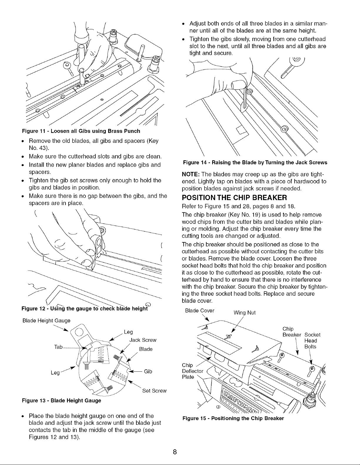
Figure 11 - Loosen all Gibs using Brass Punch
• Remove the old blades, all gibs and spacers (Key
No. 43).
• Make sure the cutterhead slots and gibs are clean.
• Install the new planer blades and replace gibs and
spacers.
• Tighten the gib set screws only enough to hold the
gibs and blades in position.
• Make sure there is no gap between the gibs, and the
spacers are in place.
Figure 12 - Using the gaugq
©
height
Blade Height Gauge
Jack Screw
Blade
Adjust both ends of all three blades in a similar man-
ner until all of the blades are at the same height.
Tighten the gibs slowly, moving from one cutterhead
slot to the next, until all three blades and all gibs are
tight and secure.
Figure 14 - Raising the Blade byTurning the Jack Screws
NOTE: The blades may creep up as the gibs are tight-
ened. Lightly tap on blades with a piece of hardwood to
position blades against jack screws if needed.
POSITION THE CHIP BREAKER
Refer to Figure 15 and 28, pages 8 and 18.
The chip breaker (Key No. 19) is used to help remove
wood chips from the cutter bits and blades while plan-
ing or molding. Adjust the chip breaker every time the
cutting tools are changed or adjusted.
The chip breaker should be positioned as close to the
cutterhead as possible without contacting the cutter bits
or blades. Remove the blade cover. Loosen the three
socket head bolts that hold the chip breaker and position
it as close to the cutterhead as possible, rotate the cut-
terhead by hand to ensure that there is no interference
with the chip breaker. Secure the chip breaker by tighten-
ing the three socket head bolts. Replace and secure
blade cover.
Blade Cover Wing Nut
Chip
Breaker Socket
Head
Bolts
Le( Gib
Figure 13 - Blade Height Gauge
Place the blade height gauge on one end of the
blade and adjust the jack screw until the blade just
contacts the tab in the middle of the gauge (see
Figures 12 and 13).
Chip
Deflector
Plate
Set Screw
Figure 15 - Positioning the Chip Breaker
8
MOLDING
Molding, also known as millwork or trim, can be defined
as a strip of wood milled with a plain or decorative sur-
face which is continuous throughout its length.
• To get superior molding finish, workpiece must be
planed and presized prior to molding. Always presize
the workpiece to within '_6" of the final thickness
prior to molding.
• During molding operation, do not exceed 1/4"total
depth of cut.
Certain molding profiles require outer edge clean-up.
When using such profiles the workpiece must be pre-
sized to 1/8"larger than the final width. This will allow 1_6,,
for clean-up on either side.
Certain molding profiles cut only the edge of the work-
piece. When using such profiles workpiece must be
presized to the same width as the final width.
INSTALLING CUTTER BITS
Refer to Figures 15, 16, 17 and 28, pages 8, 9 and 18.
NOTE: The cutter bits are mounted in the center of the
cutterhead (Key No. 47) using the 2" bit gibs (Key No.
42) provided. The cutter bits and the planing blades
(Key No. 44) are mounted in the cutterhead at the same
time so that planing and molding operations can be
done with the same set-up.
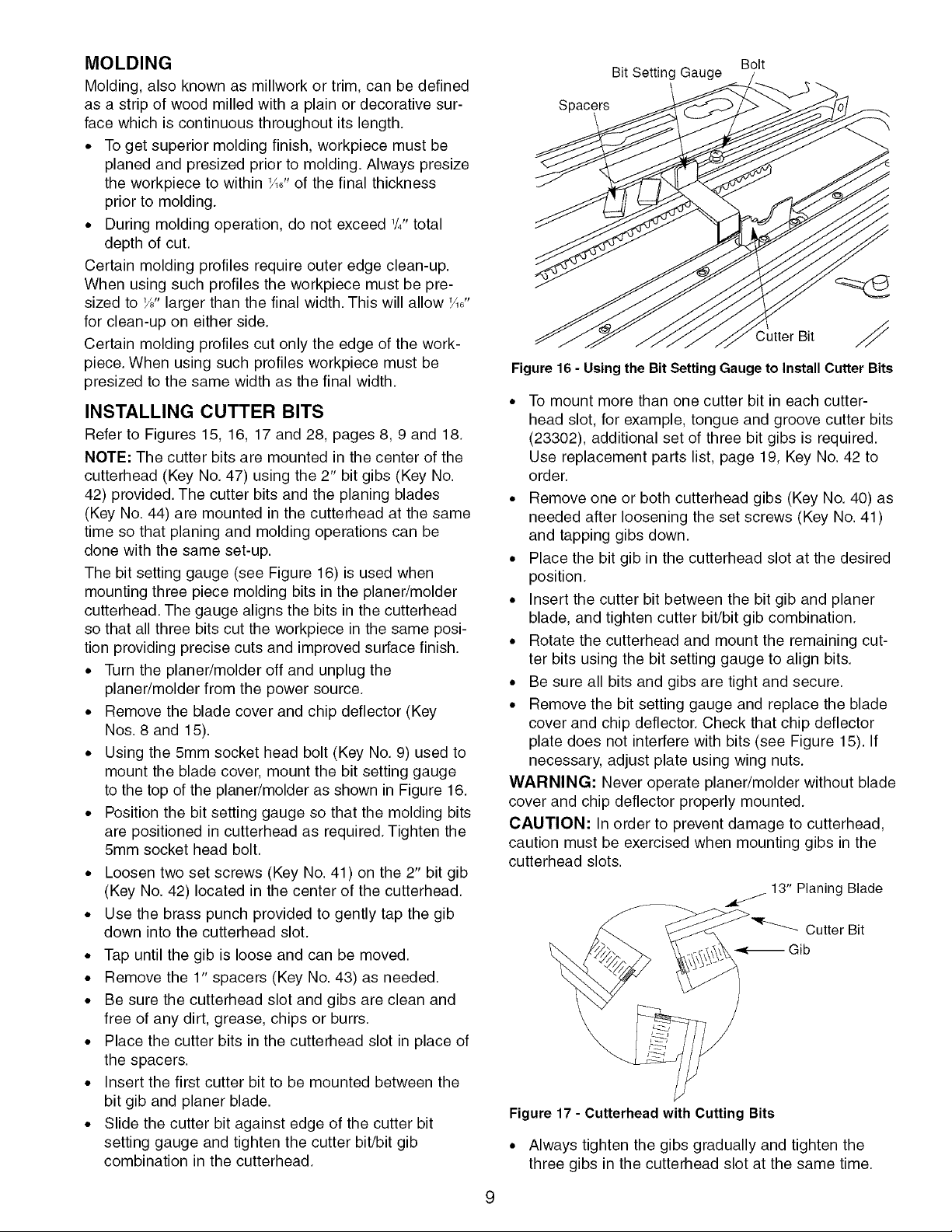
The bit setting gauge (see Figure 16) is used when
mounting three piece molding bits in the planer/molder
cutterhead. The gauge aligns the bits in the cutterhead
so that all three bits cut the workpiece in the same posi-
tion providing precise cuts and improved surface finish.
• Turn the planer/molder off and unplug the
planer/molder from the power source.
• Remove the blade cover and chip deflector (Key
Nos. 8 and 15).
• Using the 5mm socket head bolt (Key No. 9) used to
mount the blade cover, mount the bit setting gauge
to the top of the planer/molder as shown in Figure 16.
• Position the bit setting gauge so that the molding bits
are positioned in cutterhead as required. Tighten the
5mm socket head bolt.
• Loosen two set screws (Key No. 41) on the 2" bit gib
(Key No. 42) located in the center of the cutterhead.
• Use the brass punch provided to gently tap the gib
down into the cutterhead slot.
• Tap until the gib is loose and can be moved.
• Remove the 1" spacers (Key No. 43) as needed.
• Be sure the cutterhead slot and gibs are clean and
free of any dirt, grease, chips or burrs.
• Place the cutter bits in the cutterhead slot in place of
the spacers.
• Insert the first cutter bit to be mounted between the
bit gib and planer blade.
• Slide the cutter bit against edge of the cutter bit
setting gauge and tighten the cutter bit/bit gib
combination in the cutterhead.
Bit Setting Gauge
Spacers
Figure 16 - Using the Bit Setting Gauge to Install Cutter Bits
Bolt
Cutter Bit ,_
• To mount more than one cutter bit in each cutter-
head slot, for example, tongue and groove cutter bits
(23302), additional set of three bit gibs is required.
Use replacement parts list, page 19, Key No. 42 to
order.
• Remove one or both cutterhead gibs (Key No. 40) as
needed after loosening the set screws (Key No. 41)
and tapping gibs down.
• Place the bit gib in the cutterhead slot at the desired
position.
• Insert the cutter bit between the bit gib and planer
blade, and tighten cutter bit/bit gib combination.
• Rotate the cutterhead and mount the remaining cut-
ter bits using the bit setting gauge to align bits.
• Be sure all bits and gibs are tight and secure.
• Remove the bit setting gauge and replace the blade
cover and chip deflector. Check that chip deflector
plate does not interfere with bits (see Figure 15). If
necessary, adjust plate using wing nuts.
WARNING: Never operate planer/molder without blade
cover and chip deflector properly mounted.
CAUTION: In order to prevent damage to cutterhead,
caution must be exercised when mounting gibs in the
cutterhead slots.
13" Planing Blade
Cutter Bit
_-_ Gib
Figure 17 - Cutterhead with Cutting Bits
• Always tighten the gibs gradually and tighten the
three gibs in the cutterhead slot at the same time.
• Mountthegibinonecutterheadslotandtightenthe
setscrewsonlyenoughtoholdthegibinposition,
thenmounttheothertwogibsinthesamemanner.
• Tightenthesetscrewsononegibslightly,thentight-
entheothertwogibswithequalpressureontheset
screws.
• Continuetotightenthethreegibswithsmallamounts
ofaddedpressure,movingfromonegibtothenext,
untilallthreegibsaretightandsecure.
• Repeatthesameprocedureformountingthegibsin
theothertwocutterheadslots.
• Operatetheplaner/molderforfiveminutesand
retightenallsetscrews.
• Makesureto recheckthesetscrewsaftereverytwo
hoursofuse.
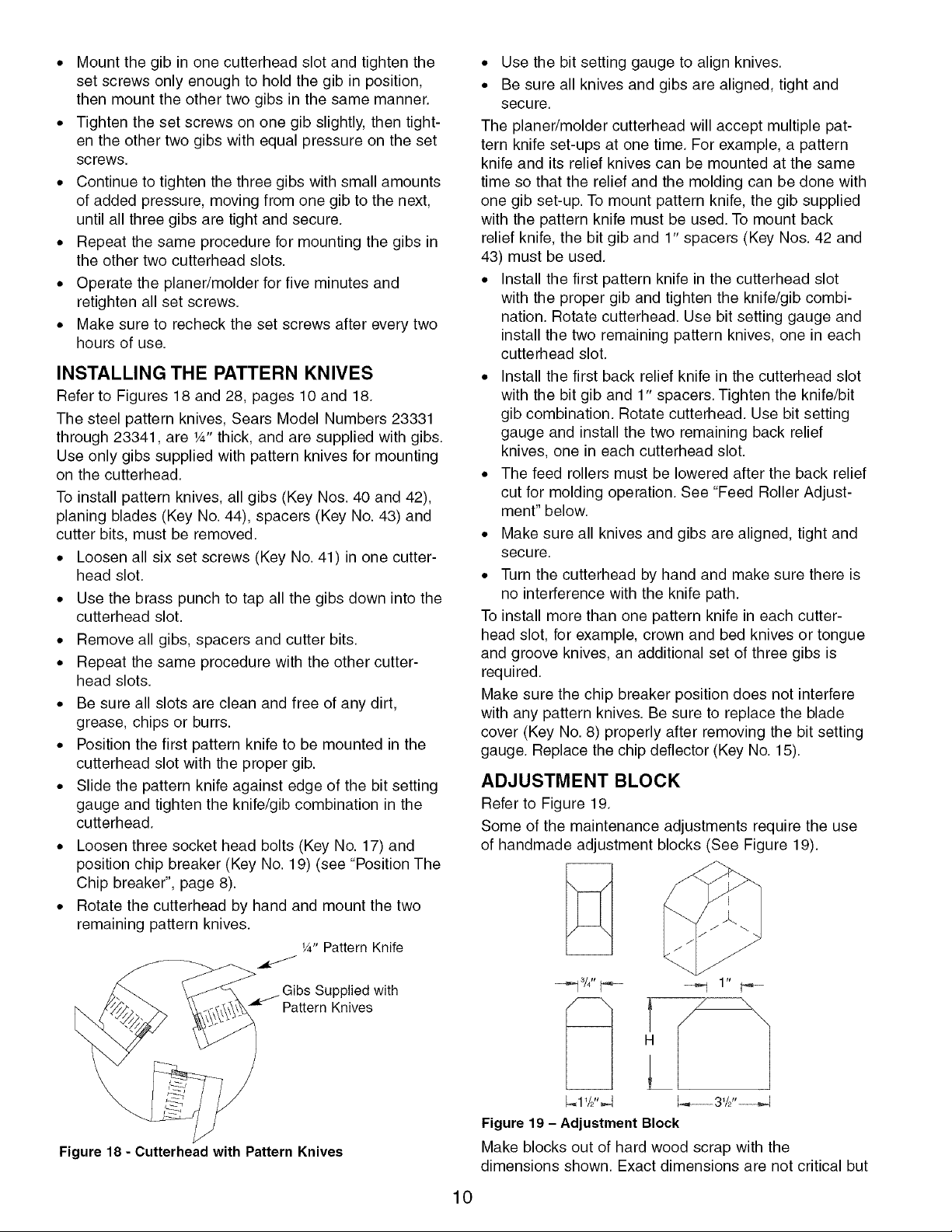
INSTALLING THE PATTERN KNIVES
Refer to Figures 18 and 28, pages 10 and 18.
The steel pattern knives, Sears Model Numbers 23331
through 23341, are 1A"thick, and are supplied with gibs.
Use only gibs supplied with pattern knives for mounting
on the cutterhead.
To install pattern knives, all gibs (Key Nos. 40 and 42),
planing blades (Key No. 44), spacers (Key No. 43) and
cutter bits, must be removed.
• Loosen all six set screws (Key No. 41) in one cutter-
head slot.
• Use the brass punch to tap all the gibs down into the
cutterhead slot.
• Remove all gibs, spacers and cutter bits.
• Repeat the same procedure with the other cutter-
head slots.
• Be sure all slots are clean and free of any dirt,
grease, chips or burrs.
• Position the first pattern knife to be mounted in the
cutterhead slot with the proper gib.
• Slide the pattern knife against edge of the bit setting
gauge and tighten the knife/gib combination in the
cutterhead.
• Loosen three socket head bolts (Key No. 17) and
position chip breaker (Key No. 19) (see "Position The
Chip breaker", page 8).
• Rotate the cutterhead by hand and mount the two
remaining pattern knives.
¼" Pattern Knife
• Use the bit setting gauge to align knives.
• Be sure all knives and gibs are aligned, tight and
secure.
The planer/molder cutterhead will accept multiple pat-
tern knife set-ups at one time. For example, a pattern
knife and its relief knives can be mounted at the same
time so that the relief and the molding can be done with
one gib set-up. To mount pattern knife, the gib supplied
with the pattern knife must be used. To mount back
relief knife, the bit gib and 1" spacers (Key Nos. 42 and
43) must be used.
• Install the first pattern knife in the cutterhead slot
with the proper gib and tighten the knife/gib combi-
nation. Rotate cutterhead. Use bit setting gauge and
install the two remaining pattern knives, one in each
cutterhead slot.
• Install the first back relief knife in the cutterhead slot
with the bit gib and 1" spacers. Tighten the knife/bit
gib combination. Rotate cutterhead. Use bit setting
gauge and install the two remaining back relief
knives, one in each cutterhead slot.
• The feed rollers must be lowered after the back relief
cut for molding operation. See "Feed Roller Adjust-
ment" below.
• Make sure all knives and gibs are aligned, tight and
secure.
• Turn the cutterhead by hand and make sure there is
no interference with the knife path.
To install more than one pattern knife in each cutter-
head slot, for example, crown and bed knives or tongue
and groove knives, an additional set of three gibs is
required.
Make sure the chip breaker position does not interfere
with any pattern knives. Be sure to replace the blade
cover (Key No.8) properly after removing the bit setting
gauge. Replace the chip deflector (Key No. 15).
ADJUSTMENT BLOCK
Refer to Figure 19.
Some of the maintenance adjustments require the use
of handmade adjustment blocks (See Figure 19).
Gibs Supplied with
Pattern Knives
Figure 18 - Cutterhead with Pattern Knives
_A" _-
_1' /2",,_
Figure 19- Adjustment Block
Make blocks out of hard wood scrap with the
dimensions shown. Exact dimensions are not critical but
10
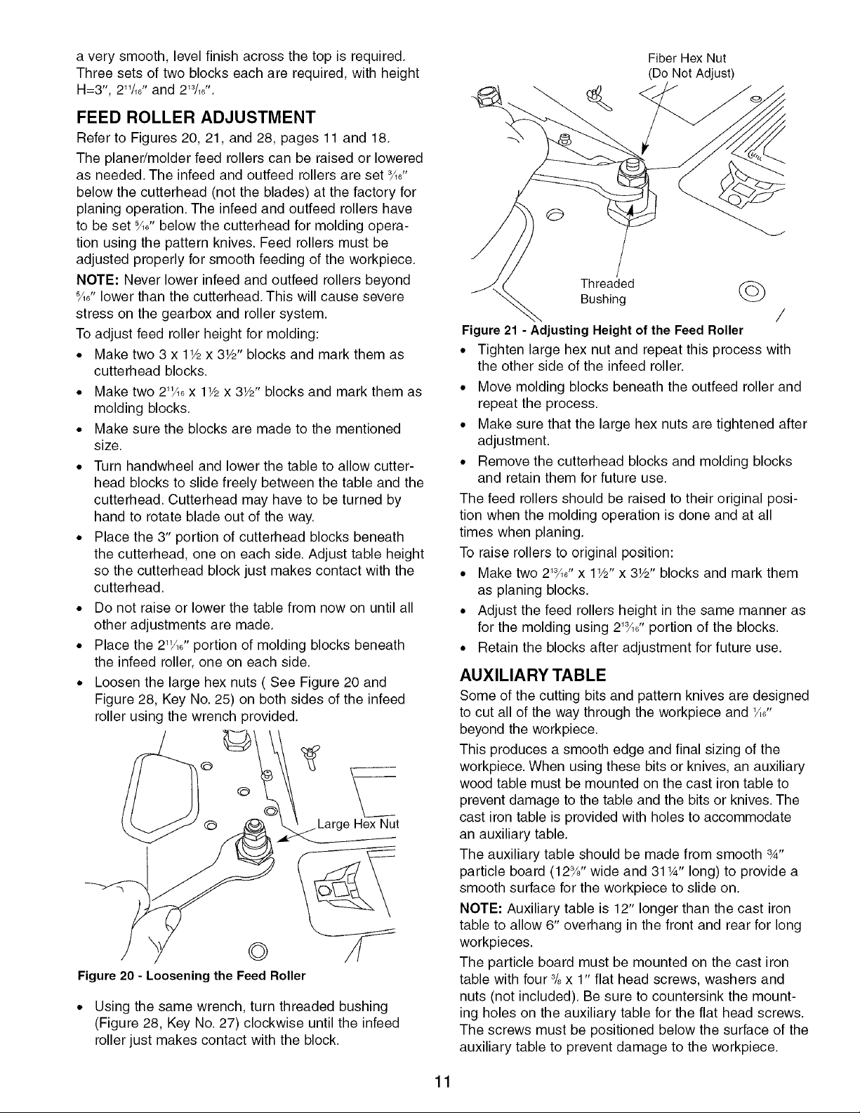
a very smooth, level finish across the top is required.
Three sets of two blocks each are required, with height
H=3", 211/,6'' and 213/,6''.
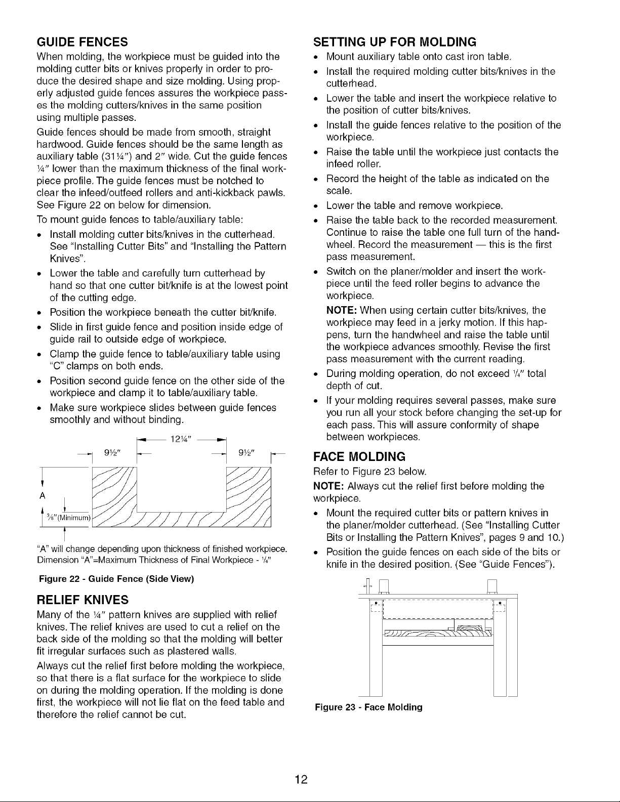
FEED ROLLER ADJUSTMENT
Refer to Figures 20, 21, and 28, pages 11 and 18.
The planer/molder feed rollers can be raised or lowered
as needed. The infeed and outfeed rollers are set _6"
below the cutterhead (not the blades) at the factory for
planing operation. The infeed and outfeed rollers have
to be set %6"below the cutterhead for molding opera-
tion using the pattern knives. Feed rollers must be
adjusted properly for smooth feeding of the workpiece.
NOTE: Never lower infeed and outfeed rollers beyond
%6"lower than the cutterhead. This will cause severe
stress on the gearbox and roller system.
To adjust feed roller height for molding:
• Make two 3 x 11/2x 3W' blocks and mark them as
cutterhead blocks.
• Make two 21_6x 11/2x 3W' blocks and mark them as
molding blocks.
• Make sure the blocks are made to the mentioned
size.
• Turn handwheel and lower the table to allow cutter-
head blocks to slide freely between the table and the
cutterhead. Cutterhead may have to be turned by
hand to rotate blade out of the way.
• Place the 3" portion of cutterhead blocks beneath
the cutterhead, one on each side. Adjust table height
so the cutterhead block just makes contact with the
cutterhead.
• Do not raise or lower the table from now on until all
other adjustments are made.
• Place the 21_16'' portion of molding blocks beneath
the infeed roller, one on each side.
• Loosen the large hex nuts ( See Figure 20 and
Figure 28, Key No. 25) on both sides of the infeed
roller using the wrench provided.
©
L_
Hex Nut
Figure 20 - Loosening the Feed Roller
• Using the same wrench, turn threaded bushing
(Figure 28, Key No. 27) clockwise until the infeed
roller just makes contact with the block.
Fiber Hex Nut
(De Not Adjust)
Threaded
Bushing (_
/
Figure 21- Adjusting Height of the Feed Roller
• Tighten large hex nut and repeat this process with
the other side of the infeed roller.
• Move molding blocks beneath the outfeed roller and
repeat the process.
• Make sure that the large hex nuts are tightened after
adjustment.
• Remove the cutterhead blocks and molding blocks
and retain them for future use.
The feed rollers should be raised to their original posi-
tion when the molding operation is done and at all
times when planing.
To raise rollers to original position:
• Make two 2_ '' x 11/2"x 31/2"blocks and mark them
as planing blocks.
• Adjust the feed rollers height in the same manner as
for the molding using 21%_'' portion of the blocks.
• Retain the blocks after adjustment for future use.
AUXILIARY TABLE
Some of the cutting bits and pattern knives are designed
to cut all of the way through the workpiece and 'A_"
beyond the workpiece.
This produces a smooth edge and final sioing of the
workpiece. When using these bits or knives, an auxiliary
wood table must be mounted on the cast iron table to
prevent damage to the table and the bits or knives. The
cast iron table is provided with holes to accommodate
an auxiliary table.
The auxiliary table should be made from smooth 3_,,
particle board (12%" wide and 31W' long) to provide a
smooth surface for the workpiece to slide on.
NOTE: Auxiliary table is 12" longer than the cast iron
table to allow 6" overhang in the front and rear for long
workpieces.
The particle board must be mounted on the cast iron
table with four 3/8x 1" flat head screws, washers and
nuts (not included). Be sure to countersink the mount-
ing holes on the auxiliary table for the flat head screws.
The screws must be positioned below the surface of the
auxiliary table to prevent damage to the workpiece.
11
GUIDE FENCES
When molding, the workpiece must be guided into the
molding cutter bits or knives properly in order to pro-
duce the desired shape and size molding. Using prop-
erly adjusted guide fences assures the workpiece pass-
es the molding cutters/knives in the same position
using multiple passes.
Guide fences should be made from smooth, straight
hardwood. Guide fences should be the same length as
auxiliary table (311/4")and 2" wide. Cut the guide fences
1/4"lower than the maximum thickness of the final work-
piece profile. The guide fences must be notched to
clear the infeed/outfeed rollers and anti-kickback pawls.
See Figure 22 on below for dimension.
To mount guide fences to table/auxiliary table:
• Install molding cutter bits/knives in the cutterhead.
See "Installing Cutter Bits" and "Installing the Pattern
Knives".
• Lower the table and carefully turn cutterhead by
hand so that one cutter bit/knife is at the lowest point
of the cutting edge.
• Position the workpiece beneath the cutter bit/knife.
• Slide in first guide fence and position inside edge of
guide rail to outside edge of workpiece.
• Clamp the guide fence to table/auxiliary table using
"C" clamps on both ends.
• Position second guide fence on the other side of the
workpiece and clamp it to table/auxiliary table.
• Make sure workpiece slides between guide fences
smoothly and without binding.
91/z'' _ 12W' _._ 9W'
I s/8 (Minirnum)_///'/_j/// //,/"_7"/_/_
t
"A"willchange depending upon thickness of finished workpiece.
Dimension 'W'=Maximum Thickness of Final Workpiece - W'
Figure 22 - Guide Fence (Side View)
SETTING UP FOR MOLDING
• Mount auxiliary table onto cast iron table.
• Install the required molding cutter bits/knives in the
cutterhead.
• Lower the table and insert the workpiece relative to
the position of cutter bits/knives.
• Install the guide fences relative to the position of the
workpiece.
• Raise the table until the workpiece just contacts the
infeed roller.
• Record the height of the table as indicated on the
scale.
• Lower the table and remove workpiece.
• Raise the table back to the recorded measurement.
Continue to raise the table one full turn of the hand-
wheel. Record the measurement -- this is the first
pass measurement.
• Switch on the planer/molder and insert the work-
piece until the feed roller begins to advance the
workpiece.
NOTE: When using certain cutter bits/knives, the
workpiece may feed in a jerky motion. If this hap-
pens, turn the handwheel and raise the table until
the workpiece advances smoothly. Revise the first
pass measurement with the current reading.
• During molding operation, do not exceed 1/4"total
depth of cut.
• If your molding requires several passes, make sure
you run all your stock before changing the set-up for
each pass. This will assure conformity of shape
between workpieces.
FACE MOLDING
Refer to Figure 23 below.
NOTE: Always cut the relief first before molding the
workpiece.
• Mount the required cutter bits or pattern knives in
the planer/molder cutterhead. (See "Installing Cutter
Bits or Installing the Pattern Knives", pages 9 and 10.)
• Position the guide fences on each side of the bits or
knife in the desired position. (See "Guide Fences").
RELIEF KNIVES
Many of the 1/4"pattern knives are supplied with relief
knives. The relief knives are used to cut a relief on the
back side of the molding so that the molding will better
fit irregular surfaces such as plastered walls.
Always cut the relief first before molding the workpiece,
so that there is a flat surface for the workpiece to slide
on during the molding operation. If the molding is done
first, the workpiece will not lie flat on the feed table and
therefore the relief cannot be cut.
Figure 23 - Face Molding
12
 Loading...