

Craftsman 351217150 Owner’s Manual

Operator's Manual
Variable Speed
WOOD LATHE
Model No.
351.21 7150
CAUTION:
Read and follow all Safety
Rules and Operating
Instructions before First
Use of this Product. Keep
this manual with tool.
Sears, Roebuck and Co., Hoffman Estates, IL 60179 U.S.A.
www.sears.com/craftsman
18062.01 Draft (04/12/05)
Warranty ......................................... 2
Safety Rules .................................... 2-3
Unpacking ....................................... 3
Assembly ........................................ 4
Installation ...................................... 4-6
Operation ..................................... 6-20
Maintenance .................................. 20-21
Troubleshooting .................................. 22
Parts Illustration and List ........................ 24-27
Espa_ol ...................................... 28-51
FULL ONE YEAR WARRANTY ON CRAFTSMAN
VARIABLE SPEED WOOD LATHE
If this Craftsman wood lathe fails to give complete satisfaction
within one full year from the date of purchase, return it to the
nearest Sears Service Center in the United States and Sears
will repair it free of charge.
Warranty service is available by contacting Sears in-home major
brand repair service. This warranty gives you specific legal rights
and you may also have other rights which vary from state to state.
If this wood lathe is used for commercial purposes, this war-
ranty applies for only 90 days from the date of purchase.
Sears, Roebuck and Co., Dept. 817 WA, Hoffman Estates, IL
60179
CAUTION: Always follow proper operating procedures as
defined in this manual -- even if you are familiar with use of
this or similar tools. Remember that being careless for even a
fraction of a second can result in severe personal injury.
BE PREPARED FOR JOB
• Wear proper apparel. Do not wear loose clothing, gloves,
neckties, rings, bracelets or other jewelry which may get
caught in moving parts of machine.
• Wear protective hair covering to contain long hair.
• Wear safety shoes with non-slip soles.
• Wear safety glasses complying with United States ANSI
Z87.1. Everyday glasses have only impact resistant lenses.
They are NOT safety glasses.
• Wear face mask or dust mask if operation is dusty.
Be alert and think clearly. Never operate power tools when
tired, intoxicated or when taking medications that cause
drowsiness.
PREPARE WORK AREA FOR JOB
Keep work area clean. Cluttered work areas invite accidents.
Do not use power tools in dangerous environments. Do not
use power tools in damp or wet locations. Do not expose
power tools to rain.
• Work area should be properly lighted.
Keep visitors at a safe distance from work area.
Keep children out of workplace. Make workshop childproof.
Use padlocks, master switches or remove switch keys to
prevent any unintentional use of power tools.
© Sears, Roebuck and Co.
Keep power cords from coming in contact with sharp
objects, oil, grease, and hot surfaces.
TOOL SHOULD BE MAINTAINED
Always unplug tool prior to inspection.
Consult manual for specific maintaining and adjusting pro-
cedures.
Keep tool lubricated and clean for safest operation.
Keep all parts in working order. Check to determine that
the guard or other parts will operate properly and perform
their intended function.
Check for damaged parts. Check for alignment of moving
parts, binding, breakage, mounting and any other condition
that may affect a tool's operation.
A guard or other part that is damaged should be properly
repaired or replaced. Do not perform makeshift repairs.
(Use parts list provided to order replacement parts.)
Never adjust attachments while running. Disconnect power
to avoid accidental start-up.
Have damaged or worn power cords replaced immediately.
Keep cutting tools sharp for efficient and safest operation.
KNOW HOW TO USE TOOL
Use right tool for job. Do not force tool or attachment to do
a job for which it was not designed.
Disconnect tool when changing attachments.
Avoid accidental start-up. Make sure that the tool is in the
"off" position before plugging in, turning on safety discon-
nect or activating breakers.
Do not force tool. It will work most efficiently at the rate for
which it was designed.
Keep hands away from chuck, centers and other moving parts.
Never leave tool running unattended. Turn the power off
and do not leave tool until it comes to a complete stop.
Do not overreach. Keep proper footing and balance.
Never stand on tool. Serious injury could occur if tool is
tipped or if centers are unintentionally contacted.
Know your tool. Learn the tool's operation, application and
specific limitations.
Handle workpiece correctly. Mount firmly in holding
devices. Protect hands from possible injury.
Turn machine off if workpiece splits or becomes loose.
Use cutting tools as recommended in "Operation."
WARNING: For your own safety, do not operate your wood
lathe until it is completely assembled and installed according to
instructions.
PROTECTION: EYES, HANDS, FACE, BODY, EARS
If any part of your lathe is missing, malfunctioning, or has
been damaged or broken, cease operating immediately
until the particular part is properly repaired or replaced.
Wear safety goggles that comply with United States ANSI
Z87.1 and a face shield or dust mask if operation is dusty.
Wear ear plugs or muffs during extended periods of operation.
Small loose pieces of wood or other objects that contact a
spinning workpiece can be propelled at very high speed.
This can be avoided by keeping the lathe clean.
Never turn the lathe ON before clearing the bed, head and
tailstock of all tools, wood scraps, etc., except the workpiece
and related support devices for the operation planned.
Never place your face or body in line with the chuck or
faceplate.
2
• Neverplaceyourfingersorhandsinpathofcuttingtools.
• Neverreachinbackoftheworkpiecewitheitherhandto
supportthepiece,removewoodscraps,orforanyother
reason.Avoidawkwardoperationsandhandpositions
whereasuddenslipcouldcausefingersorhandtomove
intoaspinningworkpiece.
• ShutthelatheOFFanddisconnectpowersourcewhen
removingthefaceplate,changingthecenter,addingor
removinganauxiliarydevice,ormakingadjustments.
• Turnkeylockswitchto"off"andremovekeywhentoolis
notinuse.
Iftheworkpiecesplitsorisdamagedinanyway,turnlathe
OFFandremovetheworkpiecefromtheholders.Discard
damagedworkpieceandstartwithanewpieceofwood.
• Useextracarewhenturningwoodwithtwistedgrainor
woodthatistwistedorbowed-- itmaycutunevenlyor
wobbleexcessively.
KNOWYOURCUTTINGTOOLS
• Dull,gummy,improperlysharpenedorsetcuttingtoolscan
causevibrationandchatterduringcuttingoperations.
Minimizepotentialinjurybypropercareoftoolsandregu-
larmachinemaintenance.
THINKSAFETY
Safetyisacombinationofoperatorcommonsenseandalert-
nessatalltimeswhenthelatheisbeingused.
Foryourownsafety,readallrulesandprecautionsinthe
operator'smanualbeforeusingthistool.
Foreye protection, wear safety glasses complying with
United States ANSI Z87.1.
• Do not wear loose clothing, gloves, neckties, rings,
bracelets or other jewelry that could get caught in moving
parts of machine or workpiece. Wear protective hair cover-
ing to contain long hair.
• Tighten all clamps, fixtures and tailstock before applying
power. Check to make sure that all tools and wrenches
have been removed.
• With switch off, rotate workpiece by hand to make sure
that there is adequate clearance. Start the machine on
lowest speed setting to verify that the workpiece is secure.
For large pieces, create a rough shape on another piece of
equipment before installing on faceplate.
• Do not mount any workpieces that have splits or knots.
Remove any center from spindle when using an outboard
device for auxiliary turning.
• Never attempt to remount a faceplate turning to the face-
plate for any reason.
• Never attempt to remount a between-centers turning if the
original centers on the turning have been altered or removed.
• When remounting a between-centers turning that has non-
altered original centers, make sure that the speed is at the
lowest setting for start-up.
• Use extra caution when mounting a between-centers turn-
ing to the faceplate, or a faceplate turning to between-cen-
ters, for secondary operations. Make sure that the speed is
at the lowest setting for start-up.
• Never perform any operation with this lathe where the
workpiece is hand-held. Do not mount a reamer, milling
cutter, drill bit, wire wheel or buffing wheel to the head-
stock spindle.
When hand-sanding faceplate or between-centers mount-
ed workpieces, complete all sanding BEFORE removing
the workpiece from the lathe.
Never run the spindle in the wrong direction. The cutting
tool could be pulled from your hands. The workpiece
should always turn towards the operator.
For spindle turning, ALWAYS position the tool rest above the
centerline of the workpiece and spindle (approximately W').
Use the drill chuck accessory in the tail stock only. Do not
mount any drill bit that extends more than 6" beyond chuck
jaws.
CAUTION: Follow safety instructions that appear on the
headstock assembly for your lathe.
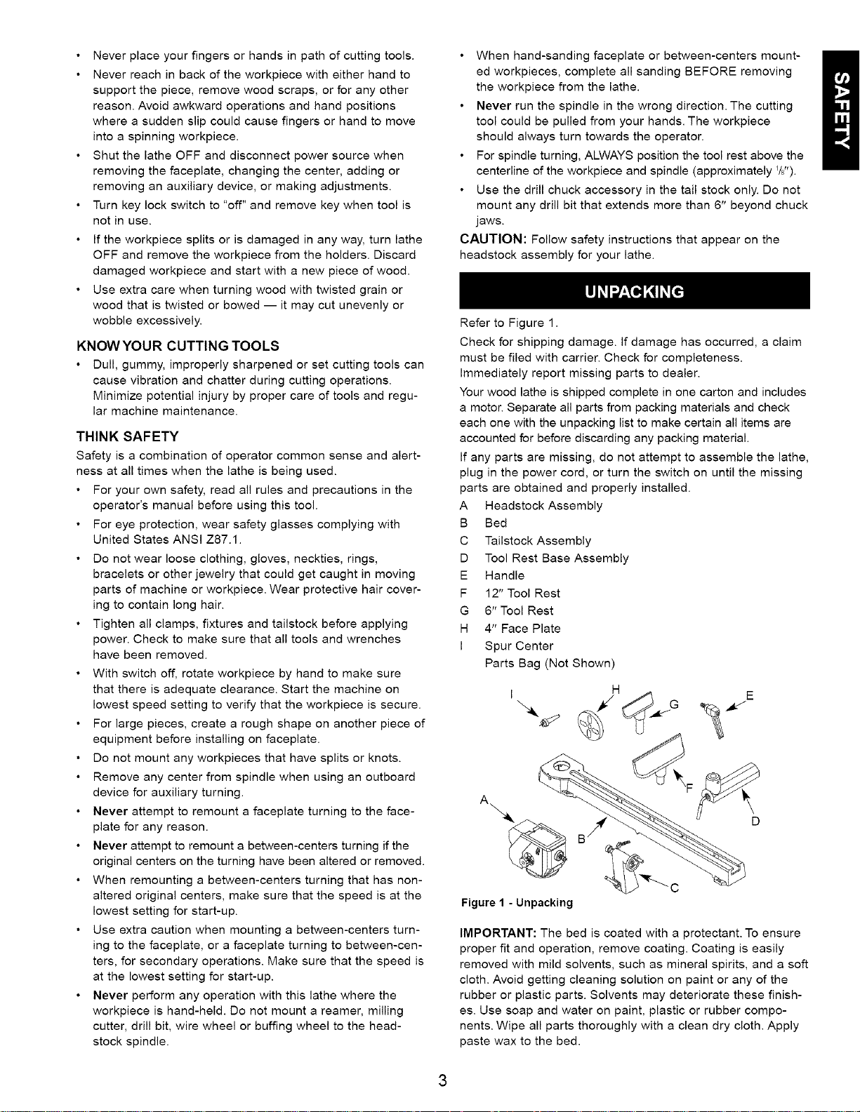
Refer to Figure 1.
Check for shipping damage. If damage has occurred, a claim
must be filed with carrier. Check for completeness.
Immediately report missing parts to dealer.
Your wood lathe is shipped complete in one carton and includes
a motor. Separate all parts from packing materials and check
each one with the unpacking list to make certain all items are
accounted for before discarding any packing material.
If any parts are missing, do not attempt to assemble the lathe,
plug in the power cord, or turn the switch on until the missing
parts are obtained and properly installed.
A Headstock Assembly
B Bed
C Tailstock Assembly
D Tool Rest Base Assembly
E Handle
F 12" Tool Rest
G 6" Tool Rest
H 4" Face Plate
I Spur Center
Parts Bag (Not Shown)
I H E
Figure 1 - Unpacking
IMPORTANT: The bed is coated with a protectant. To ensure
proper fit and operation, remove coating. Coating is easily
removed with mild solvents, such as mineral spirits, and a soft
cloth. Avoid getting cleaning solution on paint or any of the
rubber or plastic parts. Solvents may deteriorate these finish-
es. Use soap and water on paint, plastic or rubber compo-
nents. Wipe all parts thoroughly with a clean dry cloth. Apply
paste wax to the bed.
RefertoFigures2-6.
CAUTION:Donotattemptassemblyifpartsaremissing.
Usethismanualtoorderreplacementparts.
Removeallcomponentsfromtheshippingcartonandverify
againstthepartslistonpage3.Cleaneachcomponentand
removeshippingpreservatives(coatings)asrequired.
• Afterselectinganappropriatebench,table,orlathestand,set
thebedtowardsthefrontandtheleftside.
• Turnbedonitssidewiththebottomofthebedfacing
towardsyouandwiththeheadstockendofthebedonthe
leftside.
Placeheadstockassemblyonitssideneartheleftendofthe
bed.installthethreadedrodsintotheheadstock.
Headstock
Bottom
Figure 2 - Install Threaded Rods "Threaded Rod
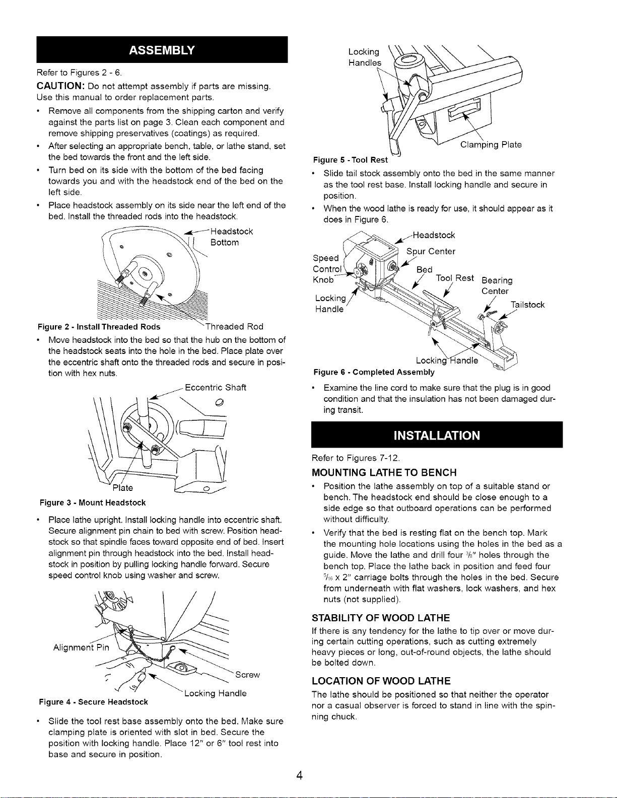
Move headstock into the bed so that the hub on the bottom of
the headstock seats into the hole in the bed. Place plate over
the eccentric shaft onto the threaded rods and secure in posi-
tion with hex nuts.
//- Eccentric Shaft
Locking
Handles
ClampingPlate
Figure 6 -Tool Rest
• Slide tail stock assembly onto the bed in the same manner
as the tool rest base. Install locking handle and secure in
position.
• When the wood lathe is ready for use, it should appear as it
does in Figure 6.
_Headstock
Spur Center
Speed
Control Bed
Knob Tool Rest Bearing
Center
Handle
Tailstock
\
Locking
Figure 6 - Completed Assembly
• Examine the line cord to make sure that the plug is in good
condition and that the insulation has not been damaged dur-
ing transit.
Plate ______
Figure 3 - Mount Headstock
Place lathe upright, install locking handle into eccentric shaft.
Secure alignment pin chain to bed with screw. Position head-
stock so that spindle faces toward opposite end of bed. Insert
alignment pin through headstock into the bed. Install head-
stock in position by pulling locking handle forward. Secure
speed control knob using washer and screw.
Alignment Pin
Locking Handle
Figure 4 - Secure Headstock
Slide the tool rest base assembly onto the bed. Make sure
clamping plate is oriented with slot in bed. Secure the
position with locking handle. Place 12" or 6" tool rest into
base and secure in position.
Refer to Figures 7-12.
MOUNTING LATHE TO BENCH
• Position the lathe assembly on top of a suitable stand or
bench. The headstock end should be close enough to a
side edge so that outboard operations can be performed
without difficulty.
• Verify that the bed is resting flat on the bench top. Mark
the mounting hole locations using the holes in the bed as a
guide. Move the lathe and drill four 3/8"holes through the
bench top. Place the lathe back in position and feed four
5/_Gx 2" carriage bolts through the holes in the bed. Secure
from underneath with flat washers, lock washers, and hex
nuts (not supplied).
STABILITY OF WOOD LATHE
If there is any tendency for the lathe to tip over or move dur-
ing certain cutting operations, such as cutting extremely
heavy pieces or long, out-of-round objects, the lathe should
be bolted down.
LOCATION OF WOOD LATHE
The lathe should be positioned so that neither the operator
nor a casual observer is forced to stand in line with the spin-
ning chuck.
4
INSTALLATION OF CENTERS
The spur center and the bearing center have Morse taper #2
to match the spindle and tail stock bores. To install the cen-
ters, slide them into the bores with a firm, swift movement.
They will be further secured when a workpiece is squeezed
between the centers.
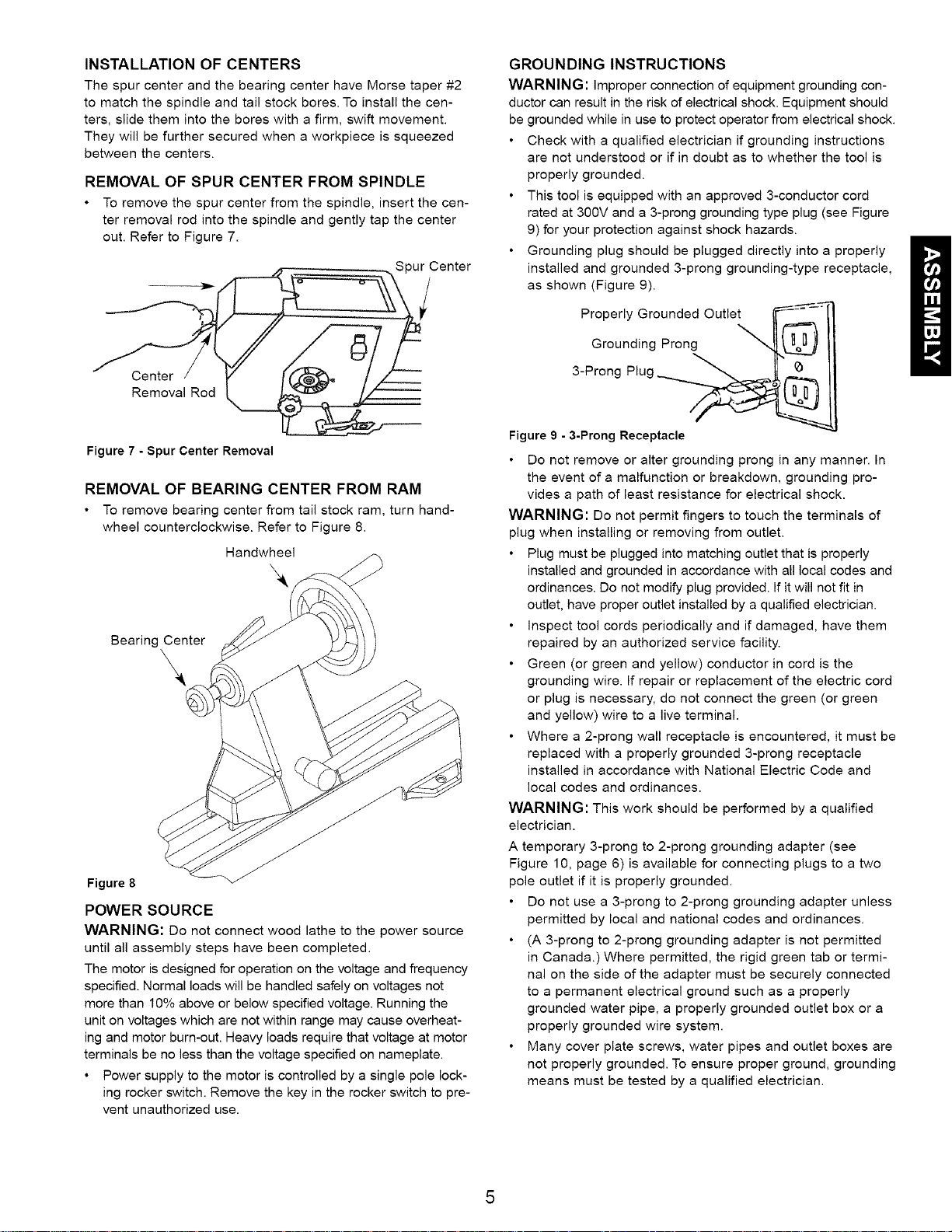
REMOVAL OF SPUR CENTER FROM SPINDLE
• To remove the spur center from the spindle, insert the cen-
ter removal rod into the spindle and gently tap the center
out. Refer to Figure 7.
Spur Center
GROUNDING INSTRUCTIONS
WARNING: improper connection of equipment grounding con-
ductor can result in the risk of electrical shock. Equipment should
be grounded while in use to protect operator from electrical shock.
Check with a qualified electrician if grounding instructions
are not understood or if in doubt as to whether the tool is
properly grounded.
This tool is equipped with an approved 3-conductor cord
rated at 300V and a 3-prong grounding type plug (see Figure
9) for your protection against shock hazards.
Grounding plug should be plugged directly into a properly N
installed and grounded 3-prong grounding-type receptacle,
as shown (Figure 9).
Properly Grounded Outlet
Grounding Prong
Center
Removal Rod
Figure 7 - Spur Center Removal
REMOVAL OF BEARING CENTER FROM RAM
• To remove bearing center from tail stock ram, turn hand-
wheel counterclockwise. Refer to Figure 8.
Handwheel
Bearing Center
\
Figure 8
POWER SOURCE
WARNING: Do not connect wood lathe to the power source
until all assembly steps have been completed.
The motor is designed for operation on the voltage and frequency
specified. Normal loads will be handled safely on voltages not
more than 10% above or below specified voltage. Running the
unit on voltages which are not within range may cause overheat-
ing and motor burn-out. Heavy loads require that voltage at motor
terminals be no less than the voltage specified on nameplate.
• Power supply to the motor is controlled by a single pole lock-
ing rocker switch. Remove the key in the rocker switch to pre-
vent unauthorized use.
3-Prong Plug
Figure 9 - 3-Prong Receptacle
Do not remove or alter grounding prong in any manner. In
the event of a malfunction or breakdown, grounding pro-
vides a path of least resistance for electrical shock.
WARNING: Do not permit fingers to touch the terminals of
plug when installing or removing from outlet.
Plug must be plugged into matching outlet that is properly
installed and grounded in accordance with all local codes and
ordinances. Do not modify plug provided. If it will not fit in
outlet, have proper outlet installed by a qualified electrician.
inspect tool cords periodically and if damaged, have them
repaired by an authorized service facility.
Green (or green and yellow) conductor in cord is the
grounding wire. If repair or replacement of the electric cord
or plug is necessary, do not connect the green (or green
and yellow) wire to a live terminal.
Where a 2-prong wall receptacle is encountered, it must be
replaced with a properly grounded 3-prong receptacle
installed in accordance with National Electric Code and
local codes and ordinances.
WARNING: This work should be performed by a qualified
electrician.
A temporary 3-prong to 2-prong grounding adapter (see
Figure 10, page 6) is available for connecting plugs to a two
pole outlet if it is properly grounded.
Do not use a 3-prong to 2-prong grounding adapter unless
permitted by local and national codes and ordinances.
(A 3-prong to 2-prong grounding adapter is not permitted
in Canada.) Where permitted, the rigid green tab or termi-
nal on the side of the adapter must be securely connected
to a permanent electrical ground such as a properly
grounded water pipe, a properly grounded outlet box or a
properly grounded wire system.
Many cover plate screws, water pipes and outlet boxes are
not properly grounded. To ensure proper ground, grounding
means must be tested by a qualified electrician.
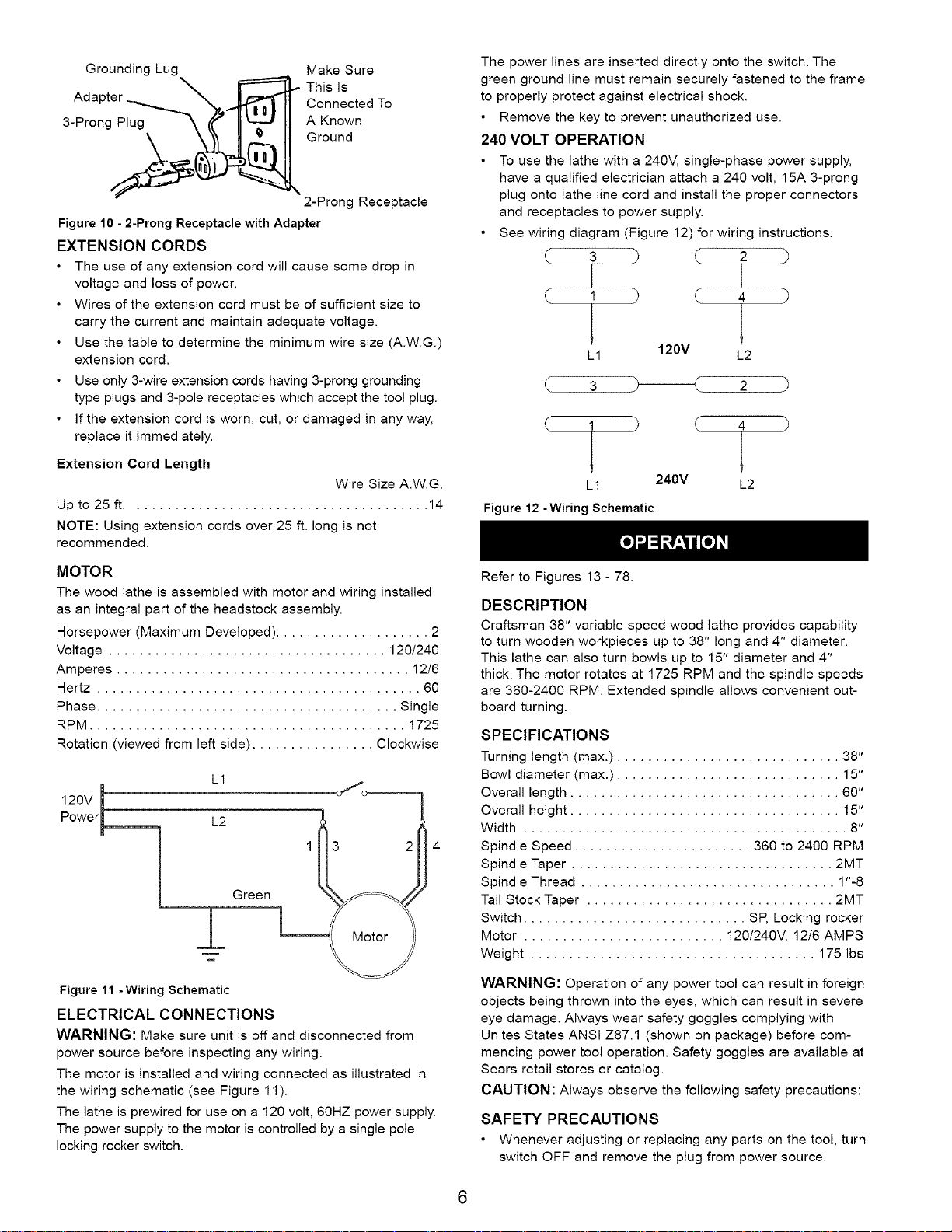
Grounding Lug Make Sure
Adapter Connected To
3-Prong_..i ,_ AGroundKnown
Figure 10 - 2-Prong Receptacle with Adapter
EXTENSION CORDS
• The use of any extension cord will cause some drop in
voltage and loss of power.
• Wires of the extension cord must be of sufficient size to
carry the current and maintain adequate voltage.
Use the table to determine the minimum wire size (A.W.G.)
extension cord.
Use only 3-wire extension cords having 3-prong grounding
type plugs and 3-pole receptacles which accept the tool plug.
If the extension cord is worn, cut, or damaged in any way,
replace it immediately.
Extension Cord Length
Up to 25 ft ....................................... 14
NOTE: Using extension cords over 25 ft. long is not
recommended.
.._,_,_ This Is
2-Prong Receptacle
Wire Size A.W.G.
The power lines are inserted directly onto the switch. The
green ground line must remain securely fastened to the frame
to properly protect against electrical shock.
• Remove the key to prevent unauthorized use.
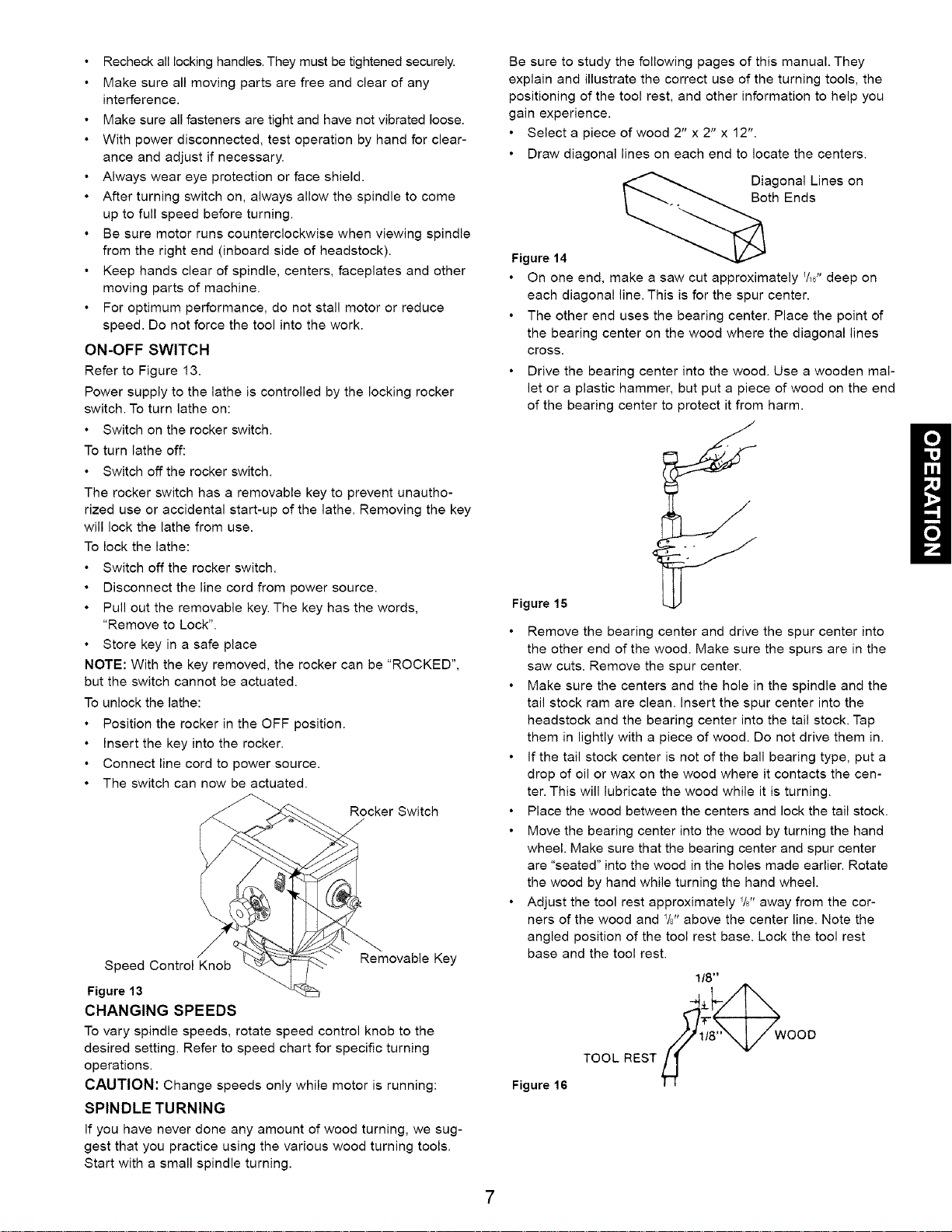
240 VOLT OPERATION
• To use the lathe with a 240V, single-phase power supply,
have a qualified electrician attach a 240 volt, 15A 3-prong
plug onto lathe line cord and install the proper connectors
and receptacles to power supply.
• See wiring diagram (Figure 12) for wiring instructions.
3 7 2 )
1 ( 4 )
L1 120V L2
3 2
1 ( 4
4
L1 240V L2
Figure 12 -Wiring Schematic
MOTOR
The wood lathe is assembled with motor and wiring installed
as an integral part of the headstock assembly.
Horsepower (Maximum Developed) .................... 2
Voltage .................................... 120/240
Amperes ...................................... 12/6
Hertz .......................................... 60
Phase ....................................... Single
RPM ......................................... 1725
Rotation (viewed from left side) ................ Clockwise
m
120V
P°wel_ L2
L1
1
Green
±
Figure 11 - Wiring Schematic
ELECTRICAL CONNECTIONS
WARNING: Make sure unit is off and disconnected from
power source before inspecting any wiring.
The motor is installed and wiring connected as illustrated in
the wiring schematic (see Figure 11).
The lathe is prewired for use on a 120 volt, 60HZ power supply.
The power supply to the motor is controlled by a single pole
locking rocker switch.
Refer to Figures 13 - 78.
DESCRIPTION
Craftsman 38" variable speed wood lathe provides capability
to turn wooden workpieces up to 38" long and 4" diameter.
This lathe can also turn bowls up to 15" diameter and 4"
thick. The motor rotates at 1725 RPM and the spindle speeds
are 360-2400 RPM. Extended spindle allows convenient out-
board turning.
SPECIFICATIONS
Turning length (max.) ............................. 38"
Bowl diameter (max.) ............................. 15"
Overall length ................................... 60"
Overall height ................................... 15"
Width .......................................... 8"
Spindle Speed ....................... 360 to 2400 RPM
Spindle Taper .................................. 2MT
Spindle Thread ................................. 1"-8
Tail Stock Taper ................................ 2MT
Switch ............................. SP, Locking rocker
Motor .......................... 120/240V, 12/6 AMPS
Weight ..................................... 175 Ibs
WARNING: Operation of any power tool can result in foreign
objects being thrown into the eyes, which can result in severe
eye damage. Always wear safety goggles complying with
Unites States ANSI Z87.1 (shown on package) before com-
mencing power tool operation. Safety goggles are available at
Sears retail stores or catalog.
CAUTION: Always observe the following safety precautions:
SAFETY PRECAUTIONS
• Whenever adjusting or replacing any parts on the tool, turn
switch OFF and remove the plug from power source.
6
Recheck all locking handles. They must be tightened securely.
• Make sure all moving parts are free and clear of any
interference.
• Make sure all fasteners are tight and have not vibrated loose.
• With power disconnected, test operation by hand for clear-
ance and adjust if necessary.
• Always wear eye protection or face shield.
• After turning switch on, always allow the spindle to come
up to full speed before turning.
• Be sure motor runs counterclockwise when viewing spindle
from the right end (inboard side of headstock).
• Keep hands clear of spindle, centers, faceplates and other
moving parts of machine.
For optimum performance, do not stall motor or reduce
speed. Do not force the tool into the work.
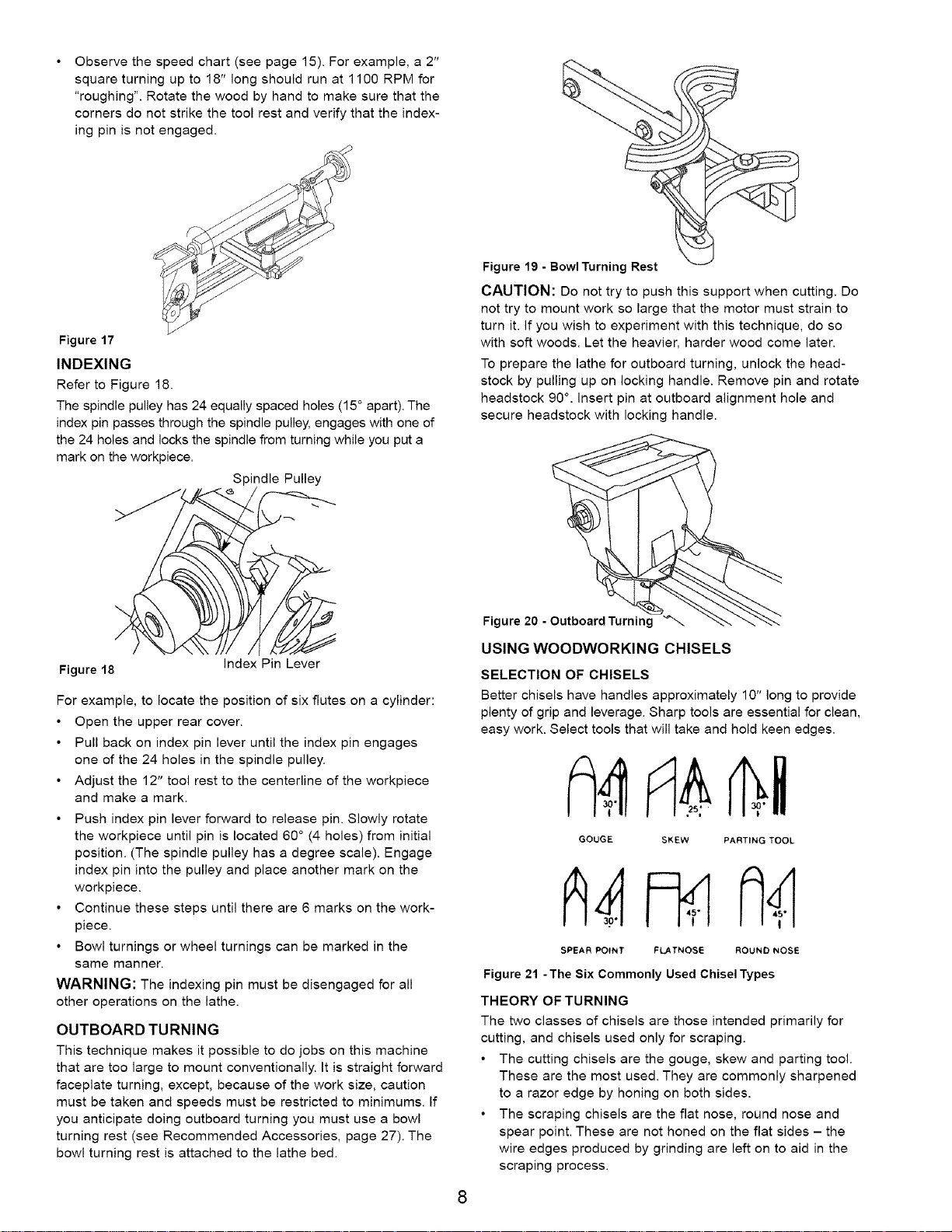
ON-OFF SWITCH
Refer to Figure 13.
Power supply to the lathe is controlled by the locking rocker
switch. To turn lathe on:
• Switch on the rocker switch.
To turn lathe off:
• Switch off the rocker switch.
The rocker switch has a removable key to prevent unautho-
rized use or accidental start-up of the lathe. Removing the key
will lock the lathe from use.
To lock the lathe:
• Switch off the rocker switch.
• Disconnect the line cord from power source.
• Pull out the removable key. The key has the words,
"Remove to Lock".
• Store key in a safe place
NOTE: With the key removed, the rocker can be "ROCKED",
but the switch cannot be actuated.
To unlock the lathe:
• Position the rocker in the OFF position.
Insert the key into the rocker.
• Connect line cord to power source.
• The switch can now be actuated.
Rocker Switch
/,
Speed Control Knob
Figure 13
CHANGING SPEEDS
To vary spindle speeds, rotate speed control knob to the
desired setting. Refer to speed chart for specific turning
operations.
Removable Key
CAUTION: Change speeds only while motor is running:
SPINDLE TURNING
If you have never done any amount of wood turning, we sug-
gest that you practice using the various wood turning tools.
Start with a small spindle turning.
Be sure to study the following pages of this manual. They
explain and illustrate the correct use of the turning tools, the
positioning of the tool rest, and other information to help you
gain experience.
Select a piece of wood 2" x 2" x 12".
Draw diagonal lines on each end to locate the centers.
Diagonal Lines on
Both Ends
Figure 14
On one end, make a saw cut approximately _/,6"deep on
each diagonal line. This is for the spur center.
The other end uses the bearing center. Place the point of
the bearing center on the wood where the diagonal lines
cross.
Drive the bearing center into the wood. Use a wooden mal-
let or a plastic hammer, but put a piece of wood on the end
of the bearing center to protect it from harm.
Figure 15
Remove the bearing center and drive the spur center into
the other end of the wood. Make sure the spurs are in the
saw cuts. Remove the spur center.
Make sure the centers and the hole in the spindle and the
tail stock ram are clean. Insert the spur center into the
headstock and the bearing center into the tail stock. Tap
them in lightly with a piece of wood. Do not drive them in.
If the tail stock center is not of the ball bearing type, put a
drop of oil or wax on the wood where it contacts the cen-
ter. This will lubricate the wood while it is turning.
Place the wood between the centers and lock the tail stock.
Move the bearing center into the wood by turning the hand
wheel. Make sure that the bearing center and spur center
are "seated" into the wood in the holes made earlier. Rotate
the wood by hand while turning the hand wheel.
Adjust the tool rest approximately %" away from the cor-
ners of the wood and %" above the center line. Note the
angled position of the tool rest base. Lock the tool rest
base and the tool rest.
1/8"
4 wooo
Figure 16
TOOL REST
Observethespeedchart(seepage15).Forexample,a2"
squareturningupto18"longshouldrunat1100RPMfor
"roughing".Rotatethewoodbyhandtomakesurethatthe
cornersdonotstrikethetoolrestandverifythattheindex-
ingpinisnotengaged.
Figure 17
INDEXING
Refer to Figure 18.
The spindle pulley has 24 equally spaced holes (15 ° apart). The
index pin passes through the spindle pulley, engages with one of
the 24 holes and locks the spindle from turning while you put a
mark on the workpiece.
Spindle Pulley
Figure 19 -Bowl Turning Rest
CAUTION: Do not try to push this support when cutting. Do
not try to mount work so large that the motor must strain to
turn it. If you wish to experiment with this technique, do so
with soft woods. Let the heavier, harder wood come later.
To prepare the lathe for outboard turning, unlock the head-
stock by pulling up on locking handle. Remove pin and rotate
headstock 90 ° . insert pin at outboard alignment hole and
secure headstock with locking handle.
Figure 18
For example, to locate the position of six flutes on a cylinder:
Open the upper rear cover.
Pull back on index pin lever until the index pin engages
one of the 24 holes in the spindle pulley.
• Adjust the 12" tool rest to the centerline of the workpiece
and make a mark.
Push index pin lever forward to release pin. Slowly rotate
the workpiece until pin is located 60 ° (4 holes) from initial
position. (The spindle pulley has a degree scale). Engage
index pin into the pulley and place another mark on the
workpiece.
Continue these steps until there are 6 marks on the work-
piece.
Bowl turnings or wheel turnings can be marked in the
same manner.
WARNING: The indexing pin must be disengaged for all
other operations on the lathe.
OUTBOARD TURNING
This technique makes it possible to do jobs on this machine
that are too large to mount conventionally. It is straight forward
faceplate turning, except, because of the work size, caution
must be taken and speeds must be restricted to minimums. If
you anticipate doing outboard turning you must use a bowl
turning rest (see Recommended Accessories, page 27). The
bowl turning rest is attached to the lathe bed.
index Pin Lever
Figure 20 - Outboard Turning
USING WOODWORKING CHISELS
SELECTION OF CHISELS
Better chisels have handles approximately 10" long to provide
plenty of grip and leverage. Sharp tools are essential for clean,
easy work. Select tools that will take and hold keen edges.
GOUGE SKEW PARTING TOOL
SPEAR POINT FLATNOSE ROUND NOSE
Figure 21 -The Six Commonly Used Chisel Types
THEORY OF TURNING
The two classes of chisels are those intended primarily for
cutting, and chisels used only for scraping.
• The cutting chisels are the gouge, skew and parting tool.
These are the most used. They are commonly sharpened
to a razor edge by honing on both sides.
• The scraping chisels are the flat nose, round nose and
spear point. These are not honed on the flat sides - the
wire edges produced by grinding are left on to aid in the
scraping process.
8
2/
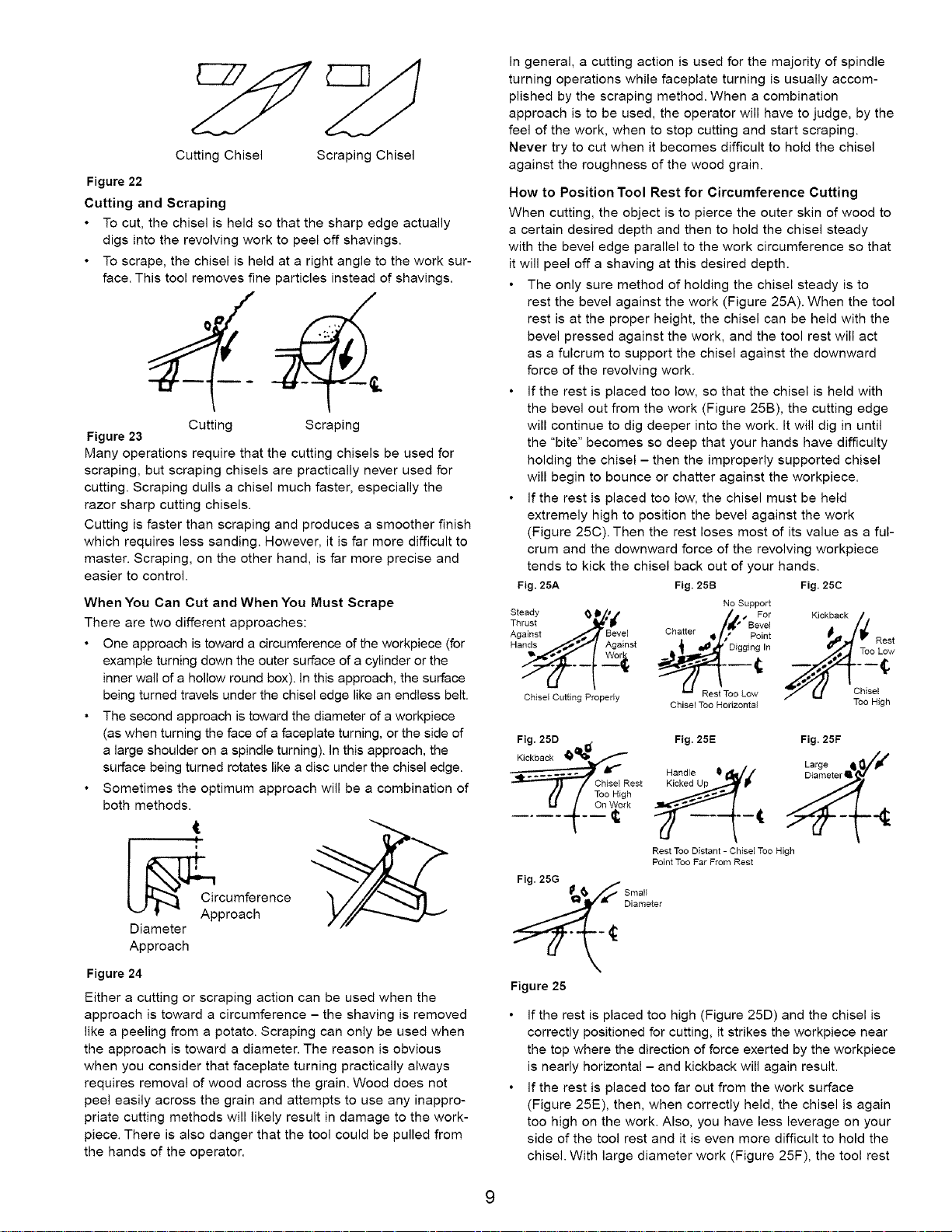
Cutting Chisel
Figure 22
Cutting and Scraping
• To cut, the chisel is held so that the sharp edge actually
digs into the revolving work to peel off shavings.
• To scrape, the chisel is held at a right angle to the work sur-
face. This tool removes fine particles instead of shavings.
Cutting Scraping
Figure 23
Many operations require that the cutting chisels be used for
scraping, but scraping chisels are practically never used for
cutting. Scraping dulls a chisel much faster, especially the
razor sharp cutting chisels.
Cutting is faster than scraping and produces a smoother finish
which requires less sanding. However, it is far more difficult to
master. Scraping, on the other hand, is far more precise and
easier to control.
When You Can Cut and When You Must Scrape
There are two different approaches:
• One approach is toward a circumference of the workpiece (for
example turning down the outer surface of a cylinder or the
inner wall of a hollow round box). in this approach, the surface
being turned travels under the chisel edge like an endless belt.
• The second approach is toward the diameter of a workpiece
(as when turning the face of a faceplate turning, or the side of
a large shoulder on a spindle turning), in this approach, the
surface being turned rotates like a disc under the chisel edge.
• Sometimes the optimum approach will be a combination of
both methods.
1
Scraping Chisel
In general, a cutting action is used for the majority of spindle
turning operations while faceplate turning is usually accom-
plished by the scraping method. When a combination
approach is to be used, the operator will have to judge, by the
feel of the work, when to stop cutting and start scraping.
Never try to cut when it becomes difficult to hold the chisel
against the roughness of the wood grain.
How to Position Tool Rest for Circumference Cutting
When cutting, the object is to pierce the outer skin of wood to
a certain desired depth and then to hold the chisel steady
with the bevel edge parallel to the work circumference so that
it will peel off a shaving at this desired depth.
The only sure method of holding the chisel steady is to
rest the bevel against the work (Figure 25A). When the tool
rest is at the proper height, the chisel can be held with the
bevel pressed against the work, and the tool rest will act
as a fulcrum to support the chisel against the downward
force of the revolving work.
If the rest is placed too low, so that the chisel is held with
the bevel out from the work (Figure 25B), the cutting edge
will continue to dig deeper into the work. It will dig in until
the "bite" becomes so deep that your hands have difficulty
holding the chisel - then the improperly supported chisel
will begin to bounce or chatter against the workpiece.
If the rest is placed too low, the chisel must be held
extremely high to position the bevel against the work
(Figure 25C). Then the rest loses most of its value as a ful-
crum and the downward force of the revolving workpiece
tends to kick the chisel back out of your hands.
Fig. 25A Fig. 25B Fig. 25C
Steady _ II/I I
Thrust "_'_
Against Bevel
Hands__o_Against
Chisel Cutting Properly
Fig. 25D , Fig. 25E
_____j_ tf io_gRTooChJSeIHighRest___ _t_
Chatter _ ,' Pgi;_
Chisel Too Horizontal
Handle Q _Z
Rest Too Distant - Chisel Too High
Point Too Far From Rest
No Support
/,t."se °e;
Rest Too Low
Kickback
Too Low
Chisel
Too High
Fig. 25F
Large _/_ If
Rest
_Circumference
Approach
Diameter
Approach
Figure 24
Either a cutting or scraping action can be used when the
approach is toward a circumference - the shaving is removed
like a peeling from a potato. Scraping can only be used when
the approach is toward a diameter. The reason is obvious
when you consider that faceplate turning practically always
requires removal of wood across the grain. Wood does not
peel easily across the grain and attempts to use any inappro-
priate cutting methods will likely result in damage to the work-
piece. There is also danger that the tool could be pulled from
the hands of the operator.
S : 'eter
Figure 25
If the rest is placed too high (Figure 25D) and the chisel is
correctly positioned for cutting, it strikes the workpiece near
the top where the direction of force exerted by the workpiece
is nearly horizontal - and kickback will again result.
If the rest is placed too far out from the work surface
(Figure 25E), then, when correctly held, the chisel is again
too high on the work. Also, you have less leverage on your
side of the tool rest and it is even more difficult to hold the
chisel. With large diameter work (Figure 25F), the tool rest
canbeabovetheworkpiececenterline,andsomewhatout
fromtheworksurface.Withsmalldiameterwork(Figure
25G),therestshouldbeclosertotheworksurface.As
workgrowssmaller,therestshouldberepositioned.
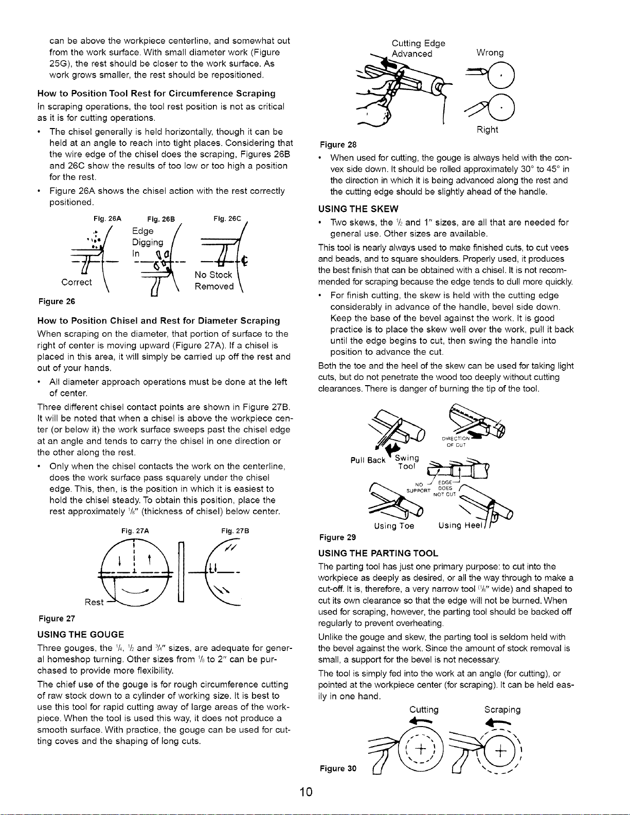
How to Position Tool Rest for Circumference Scraping
In scraping operations, the tool rest position is not as critical
as it is for cutting operations.
• The chisel generally is held horizontally, though it can be
held at an angle to reach into tight places. Considering that
the wire edge of the chisel does the scraping, Figures 26B
and 26C show the results of too low or toe high a position
for the rest.
Figure 26A shows the chisel action with the rest correctly
positioned.
Fig. 26A Fig. 26B Fig. 26C
"_" Digging [
C
Figure 26
How to Position Chisel and Rest for Diameter Scraping
When scraping on the diameter, that portion of surface to the
right of center is moving upward (Figure 27A). If a chisel is
placed in this area, it will simply be carried up off the rest and
out of your hands.
• All diameter approach operations must be done at the left
of center.
Three different chisel contact points are shown in Figure 27B.
It will be noted that when a chisel is above the workpiece cen-
ter (or below it) the work surface sweeps past the chisel edge
at an angle and tends to carry the chisel in one direction or
the other along the rest.
Only when the chisel contacts the work on the centedine,
does the work surface pass squarely under the chisel
edge. This, then, is the position in which it is easiest to
hold the chisel steady. To obtain this position, place the
rest approximately YF' (thickness of chisel) below center.
In
Fig. 27A Fig. 27B
LI___
4
Figure 27
USING THE GOUGE
Three gouges, the I/4, _t_and 3/4"sizes, are adequate for gener-
al homeshop turning. Other sizes from Y8to 2" can be pur-
chased to provide more flexibility.
The chief use of the gouge is for rough circumference cutting
of raw stock down to a cylinder of working size. It is best to
use this tool for rapid cutting away of large areas of the work-
piece. When the tool is used this way, it does not produce a
smooth surface. With practice, the gouge can be used for cut-
ting coves and the shaping of long cuts.
Cutting Edge
Advanced Wrong
Right
Figure 28
When used for cutting, the gouge is always held with the con-
vex side down. it should be rolled approximately 30 ° to 45 ° in
the direction in which it is being advanced along the rest and
the cutting edge should be slightly ahead of the handle.
USING THE SKEW
• Two skews, the _/2and 1" sizes, are all that are needed for
general use. Other sizes are available.
This tool is nearly always used to make finished cuts, to cut vees
and beads, and to square shoulders. Properly used, it produces
the best finish that can be obtained with a chisel. It is not recom-
mended for scraping because the edge tends to dull more quickly.
• For finish cutting, the skew is held with the cutting edge
considerably in advance of the handle, bevel side down.
Keep the base of the bevel against the work. It is good
practice is to place the skew well over the work, pull it back
until the edge begins to cut, then swing the handle into
position to advance the cut.
Both the toe and the heel of the skew can be used for taking light
cuts, but do not penetrate the wood too deeply without cutting
clearances. There is danger of burning the tip of the tool.
Pul! Ba_c_kS_wing
Tool
Using Toe Using Heel I/v
Figure 29
USING THE PARTING TOOL
The parting tool has just one primary purpose: to cut into the
workpiece as deeply as desired, or all the way through to make a
cut-off. It is, therefore, a very narrow tool _/8"wide) and shaped to
cut its own clearance so that the edge will not be burned. When
used for scraping, however, the parting tool should be backed off
regularly to prevent overheating.
Unlike the gouge and skew, the parting tool is seldom held with
the bevel against the work. Since the amount of stock removal is
small, a support for the bevel is not necessary.
The tool is simply fed into the work at an angle (for cutting), or
pointed at the workpiece center (for scraping). It can be held eas-
ily in one hand.
Cutting Scraping
OF CUT
4--..- 4"-'-
F,gure o d/
10
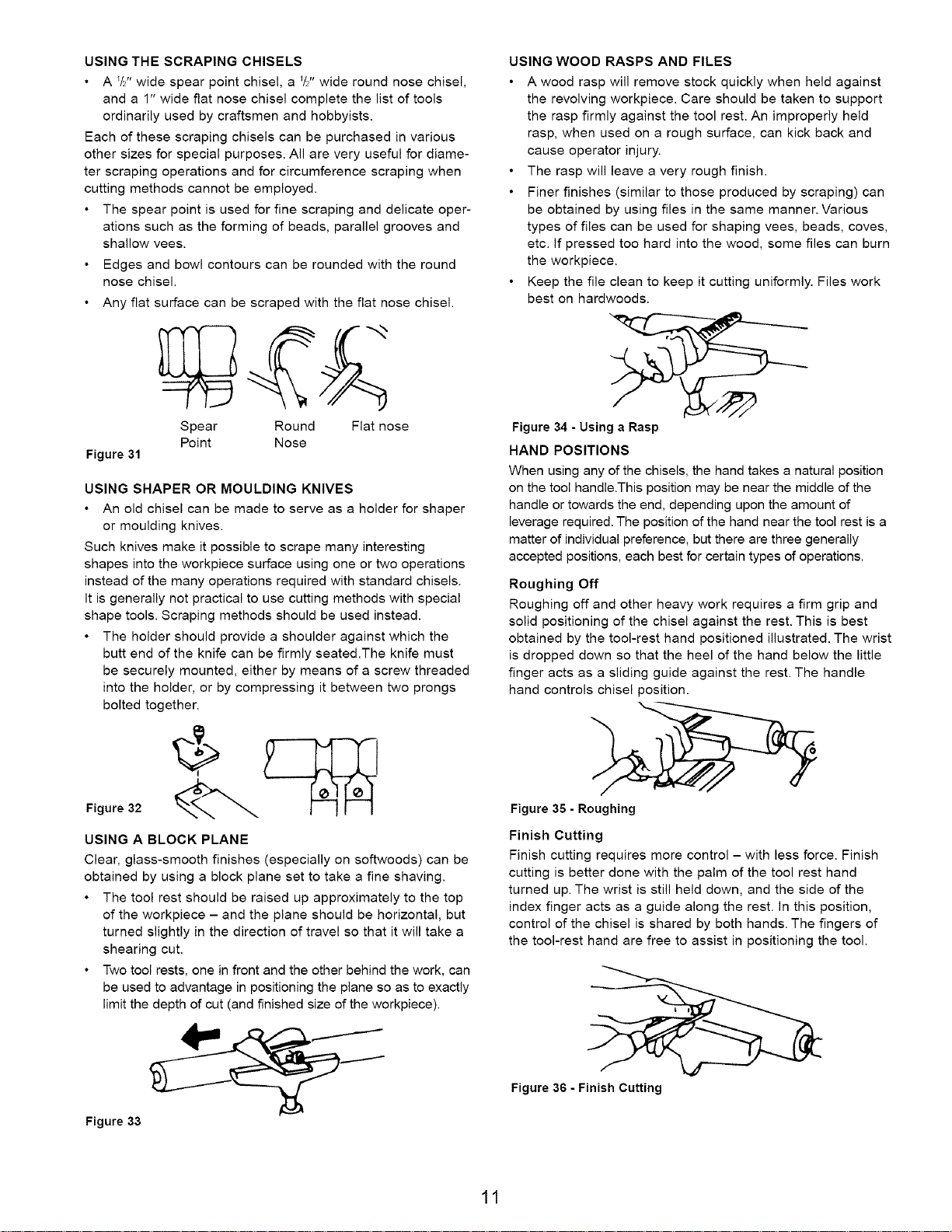
USING THE SCRAPING CHISELS
• A I/2" wide spear point chisel, a W' wide round nose chisel,
and a 1" wide flat nose chisel complete the list of tools
ordinarily used by craftsmen and hobbyists.
Each of these scraping chisels can be purchased in various
other sizes for special purposes. All are very useful for diame-
ter scraping operations and for circumference scraping when
cutting methods cannot be employed.
• The spear point is used for fine scraping and delicate oper-
ations such as the forming of beads, parallel grooves and
shallow vees.
Edges and bowl contours can be rounded with the round
nose chisel.
• Any flat surface can be scraped with the flat nose chisel.
USING WOOD RASPS AND FILES
A wood rasp will remove stock quickly when held against
the revolving workpiece. Care should be taken to support
the rasp firmly against the tool rest. An improperly held
rasp, when used on a rough surface, can kick back and
cause operator injury.
The rasp will leave a very rough finish.
Finer finishes (similar to those produced by scraping) can
be obtained by using files in the same manner. Various
types of files can be used for shaping vees, beads, coves,
etc. If pressed too hard into the wood, some flies can burn
the workpiece.
Keep the file clean to keep it cutting uniformly. Files work
best on hardwoods.
Spear Round
Point Nose
Figure 31
USING SHAPER OR MOULDING KNIVES
• An old chisel can be made to serve as a holder for shaper
or moulding knives.
Such knives make it possible to scrape many interesting
shapes into the workpiece surface using one or two operations
instead of the many operations required with standard chisels.
it is generally not practical to use cutting methods with special
shape tools. Scraping methods should be used instead.
• The holder should provide a shoulder against which the
butt end of the knife can be firmly seated.The knife must
be securely mounted, either by means of a screw threaded
into the holder, or by compressing it between two prongs
bolted together.
Figure 32
USING A BLOCK PLANE
Clear, glass-smooth finishes (especially on softwoods) can be
obtained by using a block plane set to take a fine shaving.
• The tool rest should be raised up approximately to the top
of the workpiece - and the plane should be horizontal, but
turned slightly in the direction of travel so that it will take a
shearing cut.
• Two tool rests, one in front and the other behind the work, can
be used to advantage in positioning the plane so as to exactly
limit the depth of cut (and finished size of the workpiece).
Fiat nose
Figure 34 - Using a Rasp
HAND POSITIONS
When using any of the chisels, the hand takes a natural position
on the tool handle.This position may be near the middle of the
handle or towards the end, depending upon the amount of
leverage required. The position of the hand near the tool rest is a
matter of individual preference, but there are three generally
accepted positions, each best for certain types of operations.
Roughing Off
Roughing off and other heavy work requires a firm grip and
solid positioning of the chisel against the rest. This is best
obtained by the tool-rest hand positioned illustrated. The wrist
is dropped down so that the heel of the hand below the little
finger acts as a sliding guide against the rest. The handle
hand controls chisel position.
Figure 35 - Roughing
Finish Cutting
Finish cutting requires more control - with less force. Finish
cutting is better done with the palm of the tool rest hand
turned up. The wrist is still held down, and the side of the
index finger acts as a guide along the rest. In this position,
control of the chisel is shared by both hands. The fingers of
the tool-rest hand are free to assist in positioning the tool.
Figure 33
Figure 36 - Finish Cutting
11
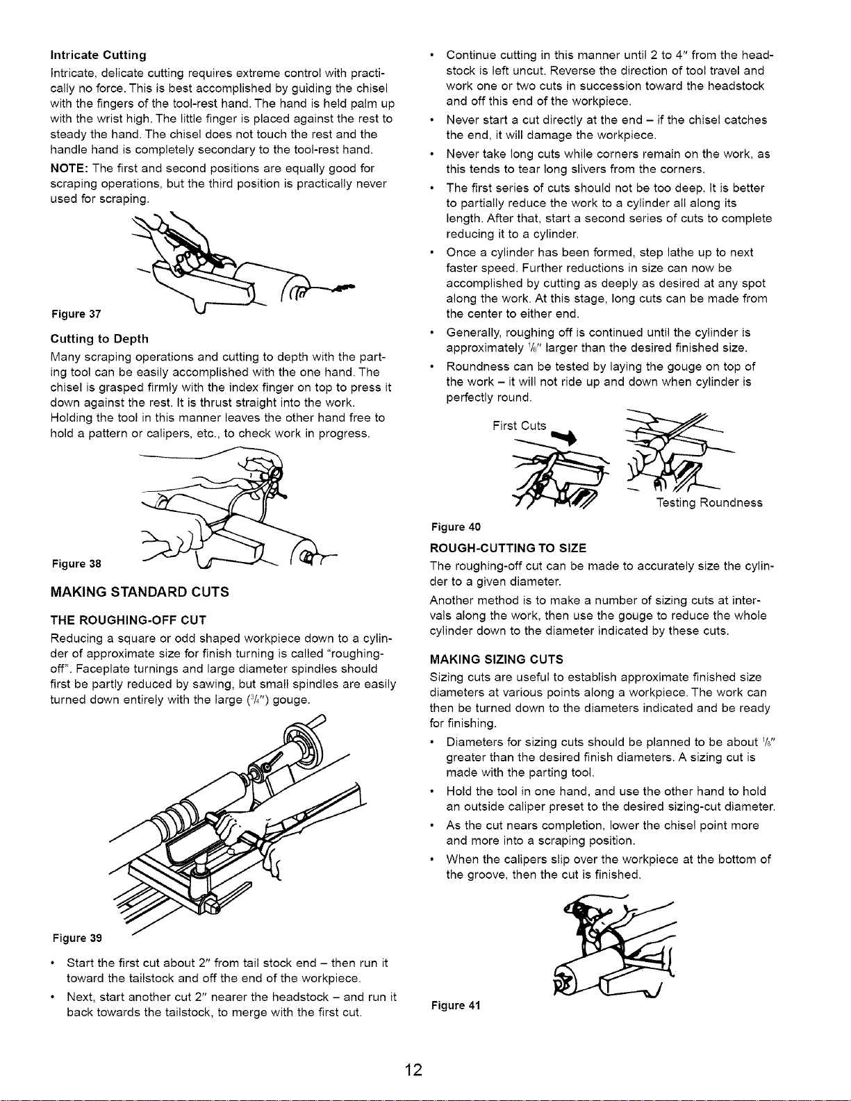
Intricate Cutting
Intricate, delicate cutting requires extreme control with practi-
cally no force. This is best accomplished by guiding the chisel
with the fingers of the tool-rest hand. The hand is held palm up
with the wrist high. The little finger is placed against the rest to
steady the hand. The chisel does not touch the rest and the
handle hand is completely secondary to the tool-rest hand.
NOTE: The first and second positions are equally good for
scraping operations, but the third position is practically never
used for scraping.
Figure 37
Cutting to Depth
Many scraping operations and cutting to depth with the part-
ing tool can be easily accomplished with the one hand. The
chisel is grasped firmly with the index finger on top to press it
down against the rest. It is thrust straight into the work.
Holding the tool in this manner leaves the other hand free to
hold a pattern or calipers, etc., to check work in progress.
• Continue cutting in this manner until 2 to 4" from the head-
stock is left uncut. Reverse the direction of tool travel and
work one or two cuts in succession toward the headstock
and off this end of the workpiece.
• Never start a cut directly at the end - if the chisel catches
the end, it will damage the workpiece.
• Never take long cuts while corners remain on the work, as
this tends to tear long slivers from the corners.
• The first series of cuts should not be too deep. It is better
to partially reduce the work to a cylinder all along its
length. After that, start a second series of cuts to complete
reducing it to a cylinder.
• Once a cylinder has been formed, step lathe up to next
faster speed. Further reductions in size can now be
accomplished by cutting as deeply as desired at any spot
along the work. At this stage, long cuts can be made from
the center to either end.
• Generally, roughing off is continued until the cylinder is
approximately YJ' larger than the desired finished size.
• Roundness can be tested by laying the gouge on top of
the work - it will not ride up and down when cylinder is
perfectly round.
Figure 38
MAKING STANDARD CUTS
THE ROUGHING-OFF CUT
Reducing a square or odd shaped workpiece down to a cylin-
der of approximate size for finish turning is called "roughing-
off". Faceplate turnings and large diameter spindles should
first be partly reduced by sawing, but small spindles are easily
turned down entirely with the large (3/4") gouge.
First Cuts
Testing Roundness
Figure 40
ROUGH-CUTTING TO SIZE
The roughing-off cut can be made to accurately size the cylin-
der to a given diameter.
Another method is to make a number of sizing cuts at inter-
vals along the work, then use the gouge to reduce the whole
cylinder down to the diameter indicated by these cuts.
MAKING SIZING CUTS
Sizing cuts are useful to establish approximate finished size
diameters at various points along a workpiece. The work can
then be turned down to the diameters indicated and be ready
for finishing.
• Diameters for sizing cuts should be planned to be about _/6"
greater than the desired finish diameters. A sizing cut is
made with the parting tool.
• Hold the tool in one hand, and use the other hand to hold
an outside caliper preset to the desired sizing-cut diameter.
• As the cut nears completion, lower the chisel point more
and more into a scraping position.
• When the calipers slip over the workpiece at the bottom of
the groove, then the cut is finished.
Figure 39
Start the first cut about 2" from tail stock end - then run it
toward the tailstock and off the end of the workpiece.
Next, start another cut 2" nearer the headstock - and run it
back towards the tailstock, to merge with the first cut.
Figure 41
12
SMOOTHING A CYLINDER
The final _/8"can be removed in two ways. Either use the 1"
skew, working from the center toward both ends and taking
lighter and lighter cuts until finished, or use a block plane as
illustrated in Figure 29.
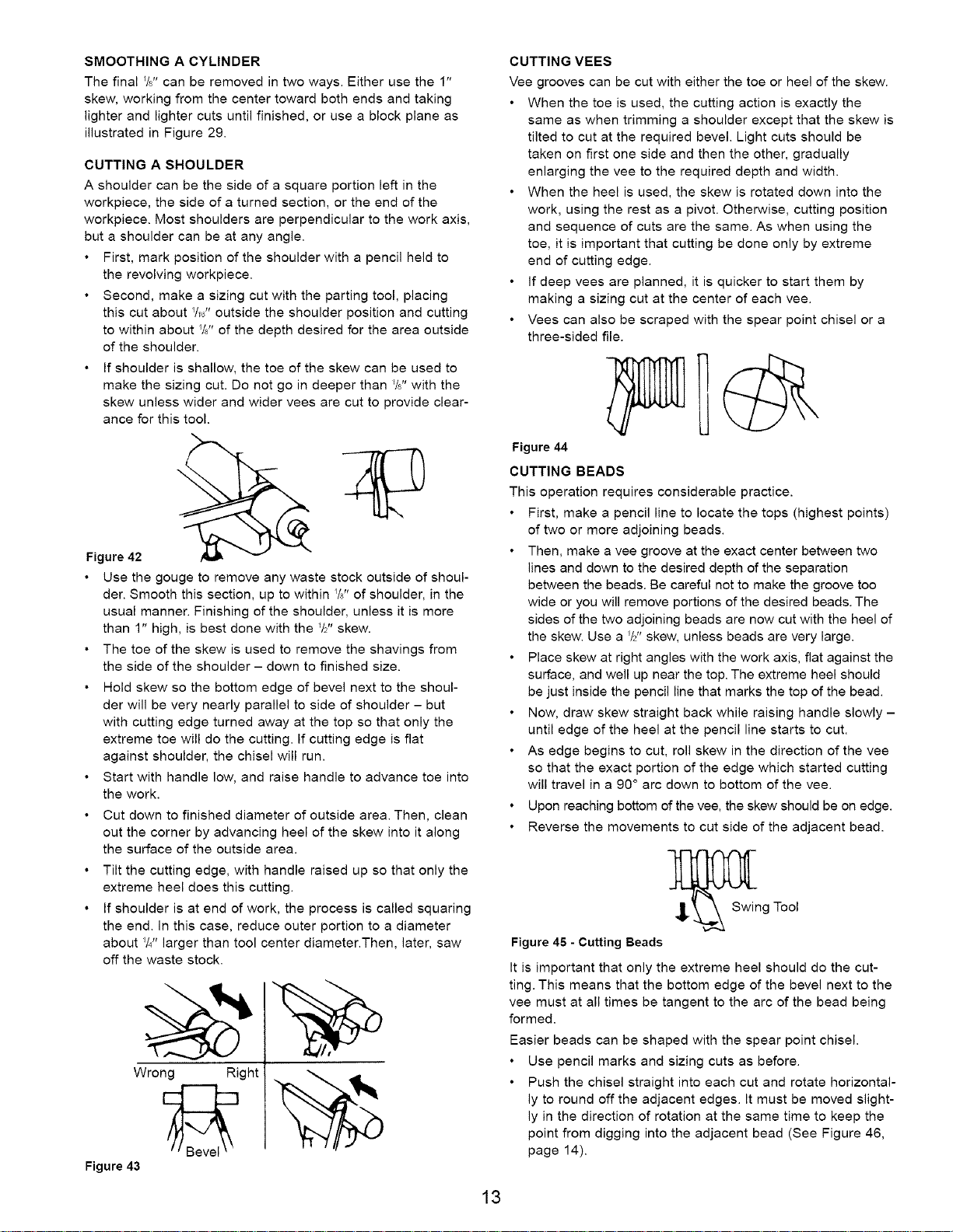
CUTTING A SHOULDER
A shoulder can be the side of a square portion left in the
workpiece, the side of a turned section, or the end of the
workpiece. Most shoulders are perpendicular to the work axis,
but a shoulder can be at any angle.
First, mark position of the shoulder with a pencil held to
the revolving workpiece.
• Second, make a sizing cut with the parting tool, placing
this cut about Y_" outside the shoulder position and cutting
to within about W' of the depth desired for the area outside
of the shoulder.
If shoulder is shallow, the toe of the skew can be used to
make the sizing cut. Do not go in deeper than W' with the
skew unless wider and wider vees are cut to provide clear-
ance for this tool.
• Use the gouge to remove any waste stock outside of shoul-
der. Smooth this section, up to within W' of shoulder, in the
usual manner. Finishing of the shoulder, unless it is more
than 1" high, is best done with the _/2"skew.
• The toe of the skew is used to remove the shavings from
the side of the shoulder - down to finished size.
Hold skew so the bottom edge of bevel next to the shoul-
der will be very nearly parallel to side of shoulder - but
with cutting edge turned away at the top so that only the
extreme toe will do the cutting. If cutting edge is fiat
against shoulder, the chisel will run.
• Start with handle low, and raise handle to advance toe into
the work.
• Cut down to finished diameter of outside area. Then, clean
out the corner by advancing heel of the skew into it along
the surface of the outside area.
• Tilt the cutting edge, with handle raised up so that only the
extreme heel does this cutting.
If shoulder is at end of work, the process is called squaring
the end. In this case, reduce outer portion to a diameter
about Y4" larger than tool center diameter.Then, later, saw
off the waste stock.
Wrong Right
Figure 43
CUTTING VEES
Vee grooves can be cut with either the toe or heel of the skew.
When the toe is used, the cutting action is exactly the
same as when trimming a shoulder except that the skew is
tilted to cut at the required bevel. Light cuts should be
taken on first one side and then the other, gradually
enlarging the vee to the required depth and width.
When the heel is used, the skew is rotated down into the
work, using the rest as a pivot. Otherwise, cutting position
and sequence of cuts are the same. As when using the
toe, it is important that cutting be done only by extreme
end of cutting edge.
If deep vees are planned, it is quicker to start them by
making a sizing cut at the center of each vee.
Vees can also be scraped with the spear point chisel or a
three-sided file.
Figure 44
CUTTING BEADS
This operation requires considerable practice.
First, make a pencil line to locate the tops (highest points)
of two or more adjoining beads.
Then, make a vee groove at the exact center between two
lines and down to the desired depth of the separation
between the beads. Be careful not to make the groove too
wide or you will remove portions of the desired beads. The
sides of the two adjoining beads are now cut with the heel of
the skew. Use a _/2"skew, unless beads are very large.
Place skew at right angles with the work axis, flat against the
surface, and well up near the top. The extreme heel should
be just inside the pencil line that marks the top of the bead.
Now, draw skew straight back while raising handle slowly -
until edge of the heel at the pencil line starts to cut.
As edge begins to cut, roll skew in the direction of the vee
so that the exact portion of the edge which started cutting
will travel in a 90 ° arc down to bottom of the vee.
Upon reaching bottom of the vee, the skew should be on edge.
Reverse the movements to cut side of the adjacent bead.
__Swing Tool
Figure 45 - Cutting Beads
It is important that only the extreme heel should do the cut-
ting. This means that the bottom edge of the bevel next to the
vee must at all times be tangent to the arc of the bead being
formed.
Easier beads can be shaped with the spear point chisel.
Use pencil marks and sizing cuts as before.
Push the chisel straight into each cut and rotate horizontal-
ly to round off the adjacent edges. It must be moved slight-
ly in the direction of rotation at the same time to keep the
point from digging into the adjacent bead (See Figure 46,
page 14).
13
_ B_evel TangentToWork
Start Finish
Figure 46
CUTTING COVES (CONCAVES)
This is the most difficult single cut to master - but one of the
most important in good wood turning.
First, use pencil marks to indicate the edges.
• Then, rough out the cove, to within about _/8"of the desired fin-
ished surface, by scraping with the gouge or round nose chis-
el. If the cove is to be very wide, sizing cuts can be made to
plot the roughing out. Once it is roughed out, the cove can be
finished in two cuts, one from each side to the bottom center.
• At the start of either cut, gouge is held with handle high
and the two sides of blade held between the thumb and
forefinger of tool rest hand, just behind the bevel.
Position the fingers so that they are ready to roll the blade
into cove.
Hold blades so that bevel is at 90 ° angle to the work axis
with point touching the pencil line and pointed into work axis.
From this start, depress point slightly to start cut, then con-
tinue to move point down in an arc toward the bottom cen-
ter cove - at the same time rolling chisel uniformly so that,
at the end of the cut, it will be fiat at the bottom of the
cove. The object is to keep the extreme point of gouge
doing the cutting from start to finish. Reverse these move-
ments to cut the opposite side.
Pencil Mark
Figure 48 - Chisel Inclined in Direction of Cut
MAKING LONG TAPER CUTS
Long taper cuts are made like long convex cuts, with the skew
or gouge. However, the angle between the cutting edge and
handle is kept constant during the entire cut. The handle is
not swung around.
• Always cut downhill. Do not cut too deeply at the center of
the taper.
SPINDLE TURNINGS
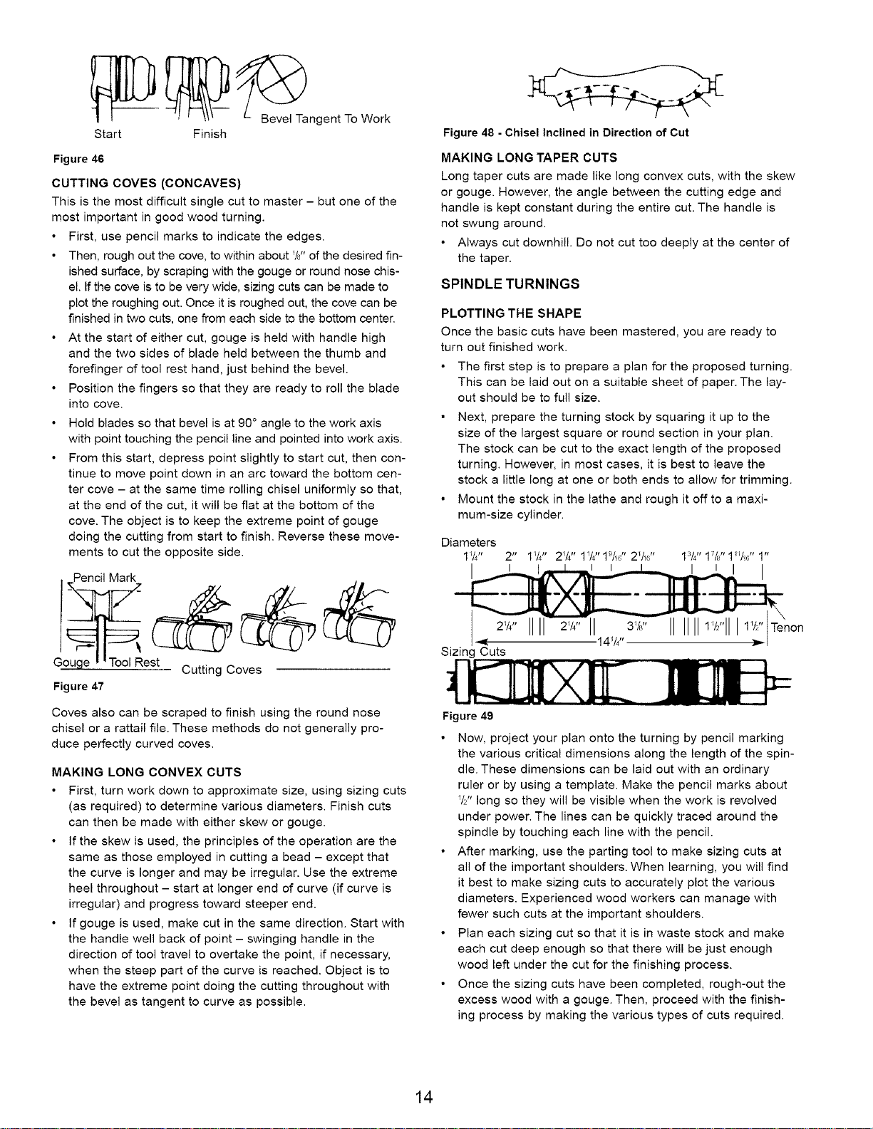
PLOTTING THE SHAPE
Once the basic cuts have been mastered, you are ready to
turn out finished work.
• The first step is to prepare a plan for the proposed turning.
This can be laid out on a suitable sheet of paper. The lay-
out should be to full size.
• Next, prepare the turning stock by squaring it up to the
size of the largest square or round section in your plan.
The stock can be cut to the exact length of the proposed
turning. However, in most cases, it is best to leave the
stock a little long at one or both ends to allow for trimming.
• Mount the stock in the lathe and rough it off to a maxi-
mum-size cylinder.
Figure 47
Coves also can be scraped to finish using the round nose
chisel or a rattail file. These methods do not generally pro-
duce perfectly curved coves.
MAKING LONG CONVEX CUTS
First, turn work down to approximate size, using sizing cuts
(as required) to determine various diameters. Finish cuts
can then be made with either skew or gouge.
If the skew is used, the principles of the operation are the
same as those employed in cutting a bead - except that
the curve is longer and may be irregular. Use the extreme
heel throughout - start at longer end of curve (if curve is
irregular) and progress toward steeper end.
If gouge is used, make cut in the same direction. Start with
the handle well back of point - swinging handle in the
direction of tool travel to overtake the point, if necessary,
when the steep part of the curve is reached. Object is to
have the extreme point doing the cutting throughout with
the bevel as tangent to curve as possible.
2v4"III II 31/j' IIIIIIl'/""JJJ11/Z''Tenon
141/4''
Sizing Cuts
Figure 49
• Now, project your plan onto the turning by pencil marking
the various critical dimensions along the length of the spin-
die. These dimensions can be laid out with an ordinary
ruler or by using a template. Make the pencil marks about
VZ' long so they will be visible when the work is revolved
under power. The lines can be quickly traced around the
spindle by touching each line with the pencil.
• After marking, use the parting tool to make sizing cuts at
all of the important shoulders. When learning, you will find
it best to make sizing cuts to accurately plot the various
diameters. Experienced wood workers can manage with
fewer such cuts at the important shoulders.
• Plan each sizing cut so that it is in waste stock and make
each cut deep enough so that there will be just enough
wood left under the cut for the finishing process.
• Once the sizing cuts have been completed, rough-out the
excess wood with a gouge. Then, proceed with the finish-
ing process by making the various types of cuts required.
14
RECOMMENDED SPEED
Always follow recommended speed to do spindle turning
depending upon the size and length of workpiece.
ROUGH FINISH
SQUARE LENGTH RPM RPM
to 2" 1 to 12" 1300 2000
to 2" to 24" 1100 2000
to 2" to 38" 1000 2000
2 to 4" 1 to 12" 1000 1800
2 to 4" to 24" 900 1600
2 to 4" to 38" 700 1400
4" Plus 1 to 12" 800 1400
4" Plus to 24" 600 1100
4" Plus to 38" 400 800
DUPLICATE TURNINGS
Identical turnings require great accuracy when plotting the
work and performing the various cuts. Many methods have
been devised to aid in perfecting the work.
Use of Patterns
Professional workers generally use a pattern or layout board. This
is a thin piece of wood or cardboard upon which is drawn a full-
size half section of the turning. The contour of the finished surface
is drawn first. Then, the diameters at various critical points are
drawn to scale as vertical lines intersecting the contour line.
By placing the pattern against the roughed-out cylinder, you
can quickly mark the various points of the critical diameters.
• To make each sizing cut, use outside calipers and set
these by actually measuring the length of the vertical lines
on the pattern which represent the diameters desired.
Make the sizing cut down to the proper diameter by using
the calipers to determine when the cut is finished.
• After making the sizing cuts, hang the pattern behind the
lathe where it will serve as a guide for completion of the
workpiece.
Figure 50
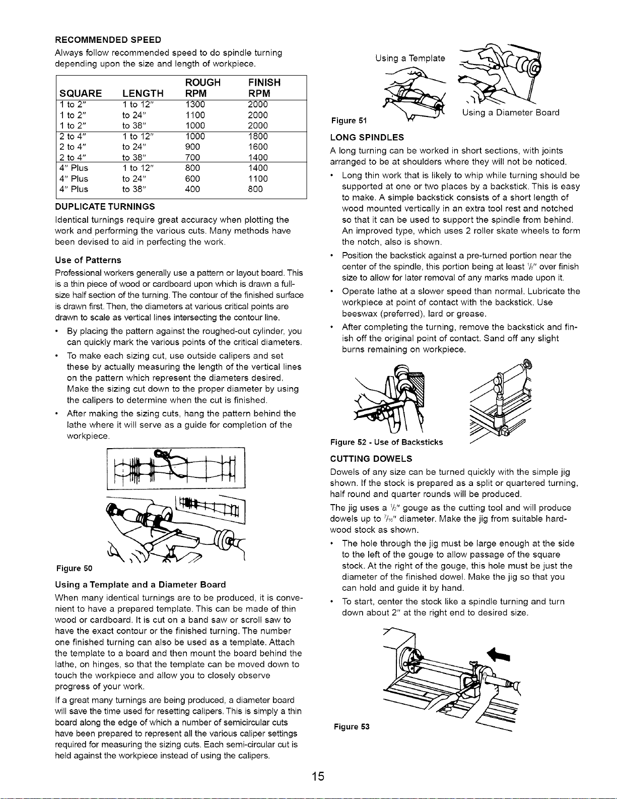
Using a Template and a Diameter Board
When many identical turnings are to be produced, it is conve-
nient to have a prepared template. This can be made of thin
wood or cardboard, it is cut on a band saw or scroll saw to
have the exact contour or the finished turning. The number
one finished turning can also be used as a template. Attach
the template to a board and then mount the board behind the
lathe, on hinges, so that the template can be moved down to
touch the workpiece and allow you to closely observe
progress of your work.
If a great many turnings are being produced, a diameter board
will save the time used for resetting calipers. This is simply a thin
board along the edge of which a number of semicircular cuts
have been prepared to represent all the various caliper settings
required for measuring the sizing cuts. Each semi-circular cut is
held against the workpiece instead of using the calipers.
Using a Template
Using a Diameter Board
Figure 51
LONG SPINDLES
A long turning can be worked in short sections, with joints
arranged to be at shoulders where they will not be noticed.
• Long thin work that is likely to whip while turning should be
supported at one or two places by a backstick. This is easy
to make. A simple backstick consists of a short length of
wood mounted vertically in an extra tool rest and notched
so that it can be used to support the spindle from behind.
An improved type, which uses 2 roller skate wheels to form
the notch, also is shown.
• Position the backstick against a pre-tumed portion near the
center of the spindle, this portion being at least YJ' over finish
size to allow for later removal of any marks made upon it.
• Operate lathe at a slower speed than normal. Lubricate the
workpiece at point of contact with the backstick. Use
beeswax (preferred), lard or grease.
• After completing the turning, remove the backstick and fin-
ish off the original point of contact. Sand off any slight
burns remaining on workpiece.
Figure 52 - Use of Backsticks
CUTTING DOWELS
Dowels of any size can be turned quickly with the simple jig
shown. If the stock is prepared as a split or quartered turning,
half round and quarter rounds will be produced.
The jig uses a _/2"gouge as the cutting tool and will produce
dowels up to 7/_6"diameter. Make the jig from suitable hard-
wood stock as shown.
• The hole through the jig must be large enough at the side
to the left of the gouge to allow passage of the square
stock. At the right of the gouge, this hole must be just the
diameter of the finished dowel. Make the jig so that you
can hold and guide it by hand.
• To start, center the stock like a spindle turning and turn
down about 2" at the right end to desired size.
Figure 53
15
Then, remove the stock. Place your jig over the turned
end, with turned portion through the smaller jig hole, and
recenter the stock on the lathe.
Hold the jig firmly and start the lathe.
Push the jig slowly right to left along the stock until the
whole dowel is completed.
MISCELLANEOUS OPERATIONS
GUIDE BLOCKS FOR SCRAPING OPERATIONS
A guide block can be clamped to a chisel to limit the depth of
cut and aid in the production of perfect cylinders, tapers and
facings on faceplate turnings. Scraping methods must be
used when the guide block is employed.
Figure 54
DRILLING
There are several methods of using the lathe for drilling cen-
ter holes through wood stock. When the drill is properly
mounted, centering of the hole is automatic.
One method is to mount a drill in the tail stock. The work-
piece is held and revolved by the headstock. If the drill has
a Morse taper shank, it can be mounted directly in some
tail stock rams. Otherwise, it can be mounted in a chuck fit-
ted with the proper type shank.
• Another method of holding the drill is to mount it in the
headstock using a 4-jaw (metal-lathe) chuck or a Jacobs
chuck. When this method is employed, there is no accurate
support for the workpiece so that center drilling is difficult.
However, cross drilling, or drilling random holes through
stock can be accomplished quickly in this manner.
FACEPLATE AND CHUCKTURNINGS
PLANNING THE WORK
Make a layout first, to provide a visual pattern to follow while
working the turning. Pattern can be laid out in the same man-
ner as spindle patterns - or templates can be made which
can be held against the work for visual comparison. Circles to
locate the various critical points (at which the contours of the
faceplate take distinct form) can be quickly scribed on the
rotating work by using the dividers.
Figure 57
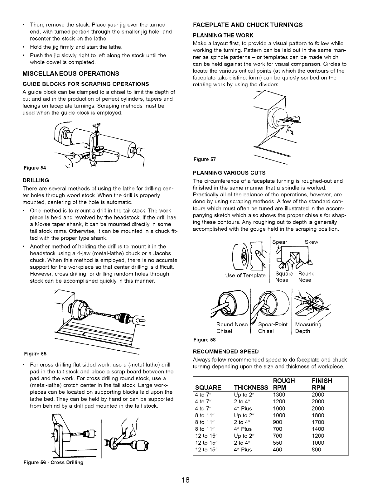
PLANNING VARIOUS CUTS
The circumference of a faceplate turning is roughed-out and
finished in the same manner that a spindle is worked.
Practically all of the balance of the operations, however, are
done by using scraping methods. A few of the standard con-
tours which must often be tuned are illustrated in the accom-
panying sketch which also shows the proper chisels for shap-
ing these contours. Any roughing out to depth is generally
accomplished with the gouge held in the scraping position.
Spear Skew
Use of Template
Square Round
Nose Nose
Figure 55
For cross drilling flat sided work, use a (metal-lathe) drill
pad in the tail stock and place a scrap board between the
pad and the work. For cross drilling round stock, use a
(metal-lathe) crotch center in the tail stock. Large work-
pieces can be located on supporting blocks laid upon the
lathe bed. They can be held by hand or can be supported
from behind by a drill pad mounted in the tail stock.
Figure 56 - Cross Drilling
Round Nose Spear-Point Measuring
Chisel Chisel Depth
Figure 58
RECOMMENDED SPEED
Always follow recommended speed to do faceplate and chuck
turning depending upon the size and thickness of workpiece.
ROUGH FINISH
SQUARE THICKNESS RPM RPM
4 to 7" Up to 2" 1300 2000
4 to 7" 2 to 4" 1200 2000
4 to 7" 4" Plus 1000 2000
8 to 11" Up to 2" 1000 1800
8 to 11" 2 to 4" 900 1700
8 to 11" 4" Plus 700 1400
12 to 15" Up to 2" 700 1200
12 to 15" 2 to 4" 550 1000
12 to 15" 4" Plus 400 800
16
 Loading...