

Craftsman 351217130 Owner’s Manual
Operator's Manual
113RI:IFTSMI:IN° /
THICKNESS PLANER
Model No.
351.217130
CAUTION: Read and follow
all Safety Rules and Operating
Instructions before First Use
of this Product.
Sears, Roebuck and Co., Hoffman Estates, IL 60179 U.S.A.
16318.00 Draft (02/05/00)
Warranty .................................. 2
Safety Rules .............................. 2-3
Unpacking ................................. 3
Assembly ................................ 3-4
Installation ............................... 4-7
Operation ................................ 7-9
Maintenance ............................ 9-11
Troubleshooting ......................... 12-13
Parts Illustration and List .................. 14-19
FULL ONE YEAR WARRANTY
tf this product fails due to a defect in material or work-
manship within one year from the date of purchase,
Sears will at its option repair or replace it free of
charge.
Contact your nearest Sears Service Center to arrange
for product repair, or return this product to place of pur-
chase for replacement.
If this product is used for commercial or rental purpos-
es, this warranty will apply for 90 days from the date of
purchase.
This warranty gives you specific legal rights and you
may also have other rights which vary from state to
state.
Sears, Roebuck and Co., Dept. 817WA, Hoffman
Estates, IL 60179
WARNING: For your own safety, read all of the rules
and precautions before operating tool.
CAUTION: Always follow proper operating procedures
as defined in this manual even if you are familiar with
use of this or similar tools. Remember that being care-
less for even a fraction of a second can result in severe
personal injury.
BE PREPARED FOR JOB
• Wear proper apparel. Do not wear loose clothing,
gloves, neckties, rings, bracelets or other jewelry
which may get caught in moving parts of machine.
• Wear protective hair covering to contain long hair.
• Wear safety shoes with non-slip soles.
• Wear safety glasses complying with United States
ANSI Z87.1. Everyday glasses have only impact
resistant lenses. They are NOT safety glasses.
• Wear face mask or dust mask if operation is dusty.
• Be alert and think clearly. Never operate power tools
when tired, intoxicated or when taking medications
that cause drowsiness.
PREPARE WORK AREA FOR JOB
• Keep work area clean. Cluttered work areas invite
accidents.
• Do not use power tools in dangerous environments.
• Do not use power tools in damp or wet locations. Do
not expose power tools 1o rain.
• Work area should be properly lighted.
• Proper electrical receptacle should be available for
tool. Three prong plug should be plugged directly
into properly grounded, three-prong receptacle.
• Extension cords should have a grounding prong and
the three wires of the extension cord should be of
the correct gauge.
• Keep visitors at a safe distance from work area.
• Keep children out of workplace. Make workshop child-
proof. Use padlocks, master switches or remove switch
keys to prevent any unintentiona_ use of power tools.
TOOL SHOULD BE MAINTAINED
• Always unplug tool prior to inspection.
• Consult manual for specific maintaining and adjust-
ing procedures.
• Keep toot lubricated and clean for safest operation.
• Remove adjusting tools. Form habit of checking to
see that adjusting tools are removed before switch-
ing machine on.
• Keep all parts in working order. Check to determine
that the guard or other parts will operate properly
and perform their intended function.
• Check for damaged parts. Check for alignment of
moving parts, binding, breakage, mounting and any
other condition that may affect a tool's operation.
• A guard or other part that is damaged should be
properly repaired or replaced. Do not perform
makeshift repairs. (Use parts list provided to order
replacement parts.)
KNOW HOW TO USE TOOL
• Use right tool for job. Do not force tool or attachment
to do a job for which it was not designed.
• Disconnect tool when changing blades.
• Avoid accidental start-up. Make sure that the switch
is in the "off" position before plugging in.
• Do not force tool. It will work most efficiently at the
rate for which it was designed.
• Keep hands away from moving parts and cutting
surfaces.
• Never leave tool running unattended. Turn the power
off and do not leave tool until it comes to a complete
stop.
• Do not overreach. Keep proper footing and balance.
• Never stand on tool. Serious injury could occur if tool is
tipped or if blade is unintentionally contacted.
• Know your tool. Learn the tool's operation, applica-
tion and specific limitations.
2
• Use recommended accessories (refer to page ??).
Use Of improper accessories may cause risk of
injury to persons.
• Handle workpiece correctly. Protect hands from pos-
sible injury.
• Turn machine off if it jams. Blade jams when it digs
too deeply into workpiece. (Motor force keeps it
stuck in the work.)
• Always keep drive, cutterhead and blade guards in
place and in proper operating condition.
• Feed work into blade or cutter against direction of
rotation.
CAUTION: Think safety! Safety is a combination of
operator common sense and alertness at all times
when tool is being used.
WARNING: Do not attempt to operate tool until it is
completely assembled according to the instructions.
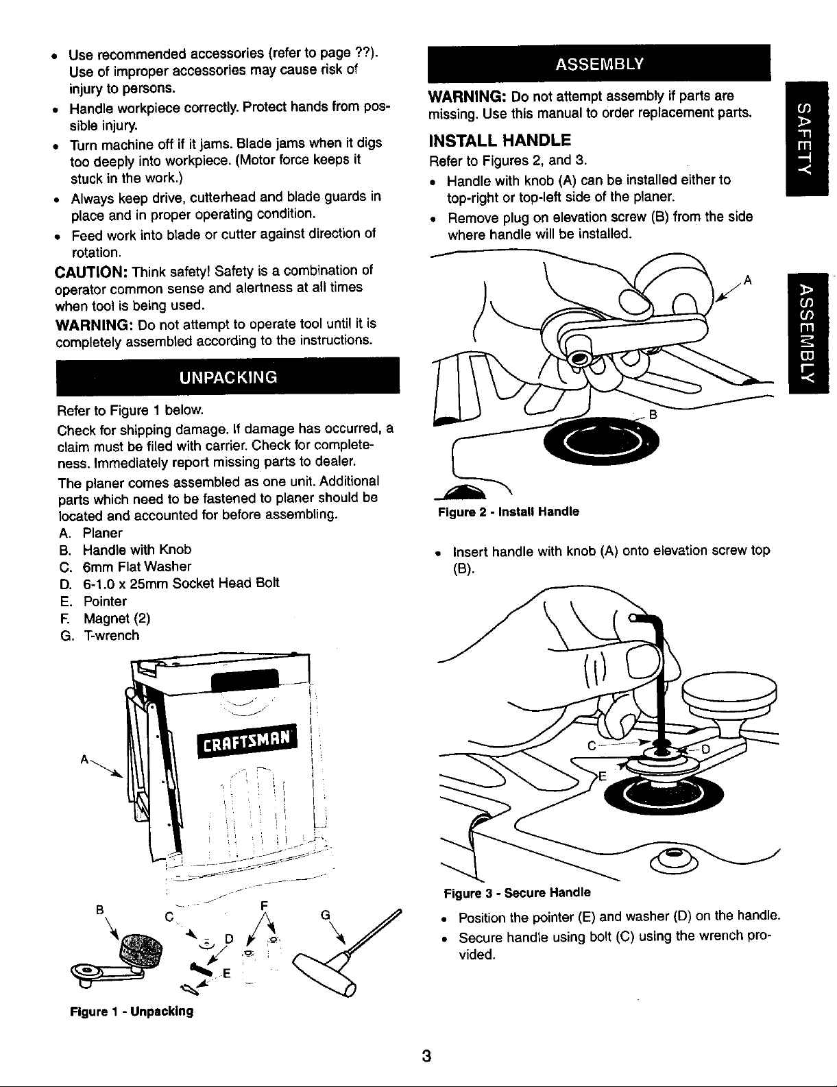
Refer to Figure 1 below.
Check for shipping damage, if damage has occurred, a
claim must be filed with carrier. Check for complete-
ness. Immediately report missing parts to dealer.
The planer comes assembled as one unit. Additional
parts which need to be fastened to planer should be
located and accounted for before assembling.
A. Planer
B. Handle with Knob
C. 6mm Flat Washer
D. 6-1+0 x 25mm Socket Head Bolt
E. Pointer
F. Magnet (2)
G. T-wrench
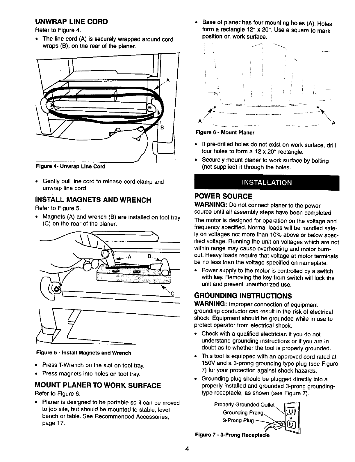
WARNING: Do not attempt assembly if parts are
missing. Use this manual to order replacement parts.
INSTALL HANDLE
Refer to Figures 2, and 3.
• Handle with knob (A) can be installed either to
top-right or top-left side of the planer.
• Remove plug on elevation screw (B) from the side
where handle will be installed.
Figure 2 - Install Handle
• Insert handle with knob (A) onto elevation screw top
(B).
Figure I - Unpacking
Figure 3 - Secure Handle
• Position the pointer (E) and washer (D) on the handle.
• Secure handle using bolt (C) using the wrench pro-
vided.
3
UNWRAP LINE CORD
Refer to Figure 4.
• The line cord (A) is securely wrapped around cord
wraps (B), on the rear of the planer.
Figure 4- Unwrap Line Cord
• Gently pull line cord to release cord clamp and
unwrap line cord
INSTALL MAGNETS AND WRENCH
Refer to Figure 5.
• Magnets (A) and wrench (B) are installed on tool tray
(C) on the rear of the planer.
• Base of planer has four mounting holes (A). Holes
form a rectangle 12" x 20". Use a square to mark
)osition on work surface,
r :
t
Aia ...........................-\,
Figure 6 - Mount Planer
• If pra-drilled holes do not exist on work surface, drill
four holes to form a 12 x 20" rectangle.
• Securely mount planer to work surface by bolting
(not supplied) it through the holes.
POWER SOURCE
WARNING: Do not connect planer to the power
source until all assembly steps have been completed.
The motor is designed for operation on the voltage and
frequency specified. Normal loads will be handled safe-
ly on voltages not more than 10% above or below spec-
ified voltage. Running the unit on voltages which are not
within range may cause overheating and motor burn-
out. Heavy loads require that voltage at motor terminals
be no less than the voltage specified on nameplate.
• Power supply to the motor is controlled by a switch
with key. Removing the key from switch will lock the
unit and prevent unauthorized use.
Figure 5 - Install Magnets and Wrench
• Press T-Wrench onthe slot on tool tray.
• Press magnets into holes on tool tray.
MOUNT PLANER TO WORK SURFACE
Refer to Figure 6.
• Planer is designed to be portable so it can be moved
to job site, but should be mounted to stable, level
bench or table. See Recommended Accessories,
page 17.
GROUNDING INSTRUCTIONS
WARNING: Improper connection of equipment
groundingconductor can result in the risk of electrical
shock. Equipment should be grounded while in use to
protect operator from electrical shock.
• Check with a qualified electrician if you do not
understand grounding instructions or if you are in
doubt as to whether the tool is properly grounded.
• This tool is equipped with an approved cord rated at
150V and a 3-prong grounding type plug (see Figure
7) for your protection against shock hazards.
• Grounding plug should be plugged directly into
properly installed and grounded 3-prong grounding-
type receptacle, as shown (see Figure 7).
Properly Grounded Outlet\ F-_
Grounding Prong "_ =.L_ II
3-Prong Plug __
Figure 7 - 3-Prong Receptacle
4
• Do not remove or alter groundingprong in any manner.
In the event of a malfunctionor breakdown, grounding
providesa path of least resistance for electricalshock.
WARNING: Do nat permit fingers to touch the termi-
nals of plug when installing or removing from outlet.
• Plug must be plugged into matching outlet that is
properly installed and grounded in accordance with
all local codes and ordinances. Do not modify plug
provided. If it will not fit in outlet, have proper outlet
installed by a qualified electrician.
• Inspect tool cords periodically, and if damaged, have
repaired by an authorized service facility.
• Green (or green and yellow) conductor in cord is the
grounding wire. If repair or replacement of the elec-
tric cord or plug is necessary, do not connect the
green (or green and yellow) wire to a live terminal.
• A 2-prong wall receptacle must be replaced with a
properly grounded 3-prong receptacle installed in
accordance with National Electric Code and local
codes and ordinances.
WARNING: Any receptacle replacement should be
performed by a qualified electrician.
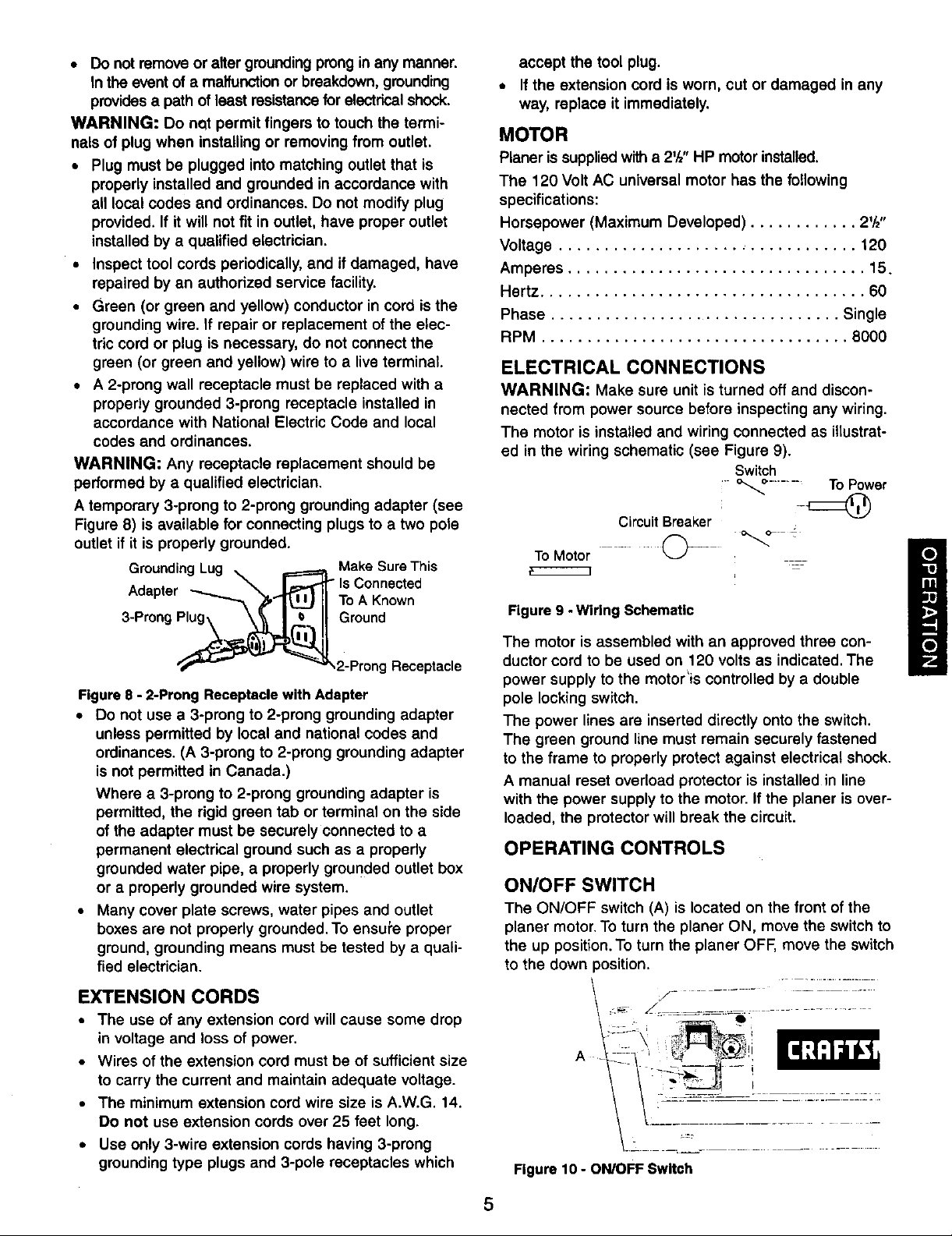
A temporary 3-prong to 2-prong grounding adapter (see
Figure 8) is available for connecting plugs to a two pole
outlet if it is properly grounded.
GroundingLug _ _Ma(_erSnerdThis
Adapter IIToAKnown
accept the tool plug.
• If the extension cord is worn, cut or damaged in any
way, replace it immediately.
MOTOR
Planer issuppliedwitha 2'/," HP motorinstalled.
The 120 Volt AC universal motor has the following
specifications:
Horsepower (Maximum Developed) ............ 2'/,"
Voltage ................................. 120
Amperes ................................. 15.
Hertz .................................... 60
Phase ................................ Single
RPM .................................. 8000
ELECTRICAL CONNECTIONS
WARNING: Make sure unit is turned off and discon-
nected from power source before inspecting any wiring.
The motor is installed and wiring connected as illustrat-
ed in the wiring schematic (see Figure 9).
Switch
" _ ........ TOPower
Circuit Breaker
To Motor
Figure 9 -Wiring Schematic
3Proo0 o,oun0
_.2-Prong Receptacle
Figure 8 - 2-Prong Receptacle with Adapter
• Do not use a 3-prong to 2-prong grounding adapter
unless permitted by local and national codes and
ordinances. (A 3-prong to 2-prong grounding adapter
is not permitted in Canada.)
Where a 3-prong to 2-prong grounding adapter is
permitted, the rigid green tab or terminal on the side
of the adapter must be securely connected to a
permanent electrical ground such as a properly
grounded water pipe, a properly grounded outlet box
or a properly grounded wire system.
• Many cover plate screws, water pipes and outlet
boxes are not properly grounded. To ensui'e proper
ground, grounding means must be tested by a quali-
fied electrician.
EXTENSION CORDS
• The use of any extension cord will cause some drop
in voltage and loss of power,
• Wires of the extension cord must be of sufficient size
to carry the current and maintain adequate voltage.
• The minimum extension cord wire size is A.W.G. 14.
Do not use extension cords over 25 feet long.
• Use only 3-wire extension cords having 3-prong
grounding type plugs and 3-pole receptacles which
The motor is assembled with an approved three con-
ductor cord to be used on 120 volts as indicated. The
power supply to the motor'is controlled by a double
pole locking switch.
The power lines are inserted directly onto the switch.
The green ground line must remain securely fastened
to the frame to properly protect against electrical shock.
A manual reset overload protector is installed in line
with the power supply to the motor. If the planer is over-
loaded, the protector will break the circuit.
OPERATING CONTROLS
ON/OFF SWITCH
The ON/OFF switch (A) is located on the front of the
planer motor. To turn the planer ON, move the switch to
the up position. To turn the planer OFF, move the switch
to the down position.
:
A
Figure 10 - ON/OFF Switch
',_--I_)_/_ _i
!
5
SWITCH LOCK
Refer to Figure 11.
The planer can be locked from unauthorized use by
locking the switch. To lock the switch:
• Turn the switch to OFF position and disconnect plan-
er from power source.
• Pull the key (A) out. The switch can not Deturned
ON with the key (A) removed.
NOTE: Should the key (A) be removed from the switch
at the ON position+the switch can be turned OFF but
cannot be turned ON.
A .
f
_/¸ :
:i-
-J" B
Figure 11 - Switch Lock and Circuit Reset
+--, -,(.... B
+c
A ¸ i
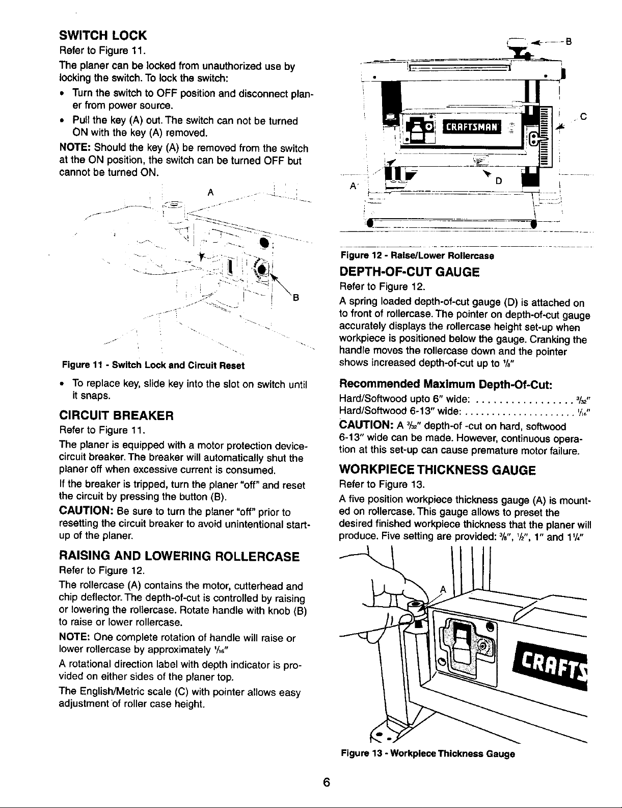
Figure 12 - Raise/Lower Rollercase
DEPTH-OF-CUT GAUGE
Refer to Figure 12.
A spring loaded depth-of-cut gauge (D) is attached on
to front of rellercase. The pointer on depth-of-cut gauge
accurately displays the rollercase height set-up when
workpiece is positioned below the gauge. Cranking the
handle moves the rollercase down and the pointer
shows increased depth-of-cut up to W'
_ '_D
..+/=
• To replace key, slide key into the slot on switch until
it snaps.
CIRCUIT BREAKER
Refer to Figure 11.
The planer is equipped with a motor protection device-
circuit breaker. The breaker will automatically shut the
planer off when excessive current is consumed.
If the breaker is tripped, turn the planer "off" and reset
the circuit by pressing the button (B).
CAUTION: Be sure to turn the planer "off" prior to
resetting the circuit breaker to avoid unintentional start-
up of the planer.
RAISING AND LOWERING ROLLERCASE
Refer to Figure 12.
The rollercase (A) contains the motor, cutterhead and
chip deflector. The depth-of-cut is controlled by raising
or lowering the roltercase. Rotate handle with knob (B)
to raise or lower rellercase.
NOTE: One complete rotation of handle will raise or
lower rollercase by approximately '/,_"
A rotational direction label with depth indicator is pro-
vided on either sides of the planer top.
The English/Metric scale (C) with pointer allows easy
adjustment of roller case height.
Recommended Maximum Depth-Of.Cut:
Hard/Softwood upto 6" wide: ................. 3/32,,
Hard/Softwood 6-1 3" wide: ..................... ,/,,,,
CAUTION: A _/_"depth-of -cut on hard, softwood
6-13" wide can be made. However, continuous opera-
tion at this set-up can cause premature motor failure.
WORKPIECE THICKNESS GAUGE
Refer to Figure 13.
A five position workpiece thickness gauge (A) is mount-
ed on rollercase. This gauge allows to preset the
desired finished workpiece thickness that the planer will
produce. Five setting are provided: %', 1/2",1" and 11/,"
Figure 13 - Workplece Thickness Gauge
6
 Loading...