

Craftsman 351217030 Owner’s Manual

Operator's Manual
8"JOINTER AND
JOINTER STAND
Model No.
351.21 7030
CAUTION: Read and follow
all Safety Rules and Operating
Instructions before First Use
of this Product.
Sears, Roebuck and Co., Hoffman Estates, IL 60179 U.S.A.
www.sears.com/craftsman
23056.00 Draft (01/21/05)

Warranty.................................... 2
SafetyRules............................... 2-3
Unpacking.................................. 3
Assembly................................. 3-5
Installation................................. 5-6
KnowYourJointer............................ 7
Operation................................ 7-11
Maintenance................................ 11
Troubleshooting............................. 12
PartsIllustrationandList................... 14-19
FULL ONE YEAR WARRANTY
If this product fails due to a defect in material or workman-
ship within one year from the date of purchase, Sears will
at its option repair or replace it free of charge. Contact
your nearest Sears Service Center (1-800-4-MY-HOME)
to arrange for product repair, or return this product to
place of purchase for replacement.
If this product is used for commercial or rental purpos-
es, this warranty will apply for 90 days from the date of
purchase.
This warranty applies only while this product is used in
the United States.
This warranty gives you specific legal rights, and you
may also have other rights which vary from state to state.
Sears, Roebuck and Co., Dept. 817WA, Hoffman
Estates, IL 60179
WARNING: For your own safety, read all of the rules
and precautions before operating tool.
CAUTION: Always follow proper operating procedures
as defined in this manual even if you are familiar with
use of this or similar tools. Remember that being care-
less for even a fraction of a second can result in severe
personal injury.
BE PREPARED FOR JOB
• Wear proper apparel. Do not wear loose clothing,
gloves, neckties, rings, bracelets or other jewelry
which may get caught in moving parts of machine.
• Wear protective hair covering to contain long hair.
• Wear safety shoes with non-slip soles.
• Wear safety glasses complying with United States
ANSI Z87.1. Everyday glasses have only impact
resistant lenses. They are NOT safety glasses.
• Wear face mask or dust mask if operation is dusty.
• Be alert and think clearly. Never operate power tools
when tired, intoxicated or when taking medications
that cause drowsiness.
© Sears, Roebuck and Co.
PREPARE WORK AREA FOR JOB
• Keep work area clean. Cluttered work areas invite
accidents.
• Do not use power tools in dangerous environments.
• Do not use power tools in damp or wet locations. Do
not expose power tools to rain.
• Work area should be properly lighted.
• Proper electrical receptacle should be available for
tool. Three prong plug should be plugged directly
into properly grounded, three-prong receptacle.
• Extension cords should have a grounding prong and
the three wires of the extension cord should be of
the correct gauge.
• Keep visitors at a safe distance from work area.
• Keep children out of workplace. Make workshop child-
proof. Use padlocks, master switches or remove switch
keys to prevent any unintentional use of power tools.
TOOL SHOULD BE MAINTAINED
• Always unplug tool prior to inspection.
• Consult manual for specific maintaining and adjust-
ing procedures.
• Keep tool lubricated and clean for safest operation.
• Remove adjusting tools. Form habit of checking to
see that adjusting tools are removed before switch-
ing machine on.
• Keep all parts in working order. Check to determine
that the guard or other parts will operate properly
and perform their intended function.
• Check for damaged parts. Check for alignment of
moving parts, binding, breakage, mounting and any
other condition that may affect a tool's operation.
• A guard or other part that is damaged should be
properly repaired or replaced. Do not perform
makeshift repairs. (Use parts list provided to order
replacement parts.)
KNOW HOW TO USE TOOL
• Use right tool for job. Do not force tool or attachment
to do a job for which it was not designed.
• Disconnect tool when changing blades.
• Avoid accidental start-up. Make sure that the switch
is in the OFF position before plugging in.
• Do not force tool. It will work most efficiently at the
rate for which it was designed.
• Keep hands away from moving parts and cutting
surfaces.
• Never leave tool running unattended. Turn the power
off and do not leave tool until it comes to a complete
stop.
• Do not overreach. Keep proper footing and balance.
• Never stand on tool. Serious injury could occur if tool is
tipped or if blade is unintentionally contacted.
• Know your tool. Learn the tool's operation, application
and specific limitations.
2
• Userecommendedaccessories(refertopage19).
Useofimproperaccessoriesmaycauseriskof
injurytopersons.
• Handleworkpiececorrectly.Protecthandsfrompos-
sibleinjury.
• Turnmachineoffifitjams.Bladejamswhenitdigs
toodeeplyintoworkpiece.(Motorforcekeepsit
stuckinthework.)
CAUTION:Thinksafety!Safetyisacombinationof
operatorcommonsenseandalertnessatalltimes
whentoolisbeingused.
G
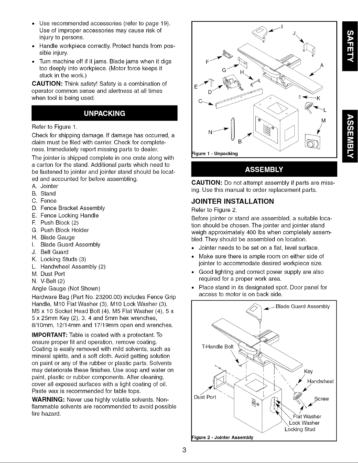
RefertoFigure1.
Checkforshippingdamage.Ifdamagehasoccurred,a
claimmustbefiledwithcarrier.Checkforcomplete-
ness.Immediatelyreportmissingpartstodealer.
Thejointerisshippedcompleteinonecratealongwith
acartonforthestand.Additionalpartswhichneedto
befastenedtojointerandjointerstandshouldbelocat-
edandaccountedforbeforeassembling.
A. Jointer
B. Stand
C. Fence
D.FenceBracketAssembly
E. FenceLockingHandle
E PushBlock(2)
G.PushBlockHolder
H.BladeGauge
I. BladeGuardAssembly
J. BeltGuard
K. LockingStuds(3)
L. HandwheelAssembly(2)
M.DustPort
N.V-Belt(2)
AngleGauge(NotShown)
HardwareBag(PartNo.23200.00)includesFenceGrip
Handle,M10FlatWasher(3),M10LockWasher(3),
M5x10SocketHeadBolt(4),M5FlatWasher(4),5 x
5x 25mmKey(2),3,4and5mmhexwrenches,
8/10mm,12/14mmand17/19mmopenendwrenches.
IMPORTANT:Tableiscoatedwitha protectant.To
ensureproperfitandoperation,removecoating.
Coatingiseasilyremovedwithmildsolvents,suchas
mineralspirits,anda softcloth.Avoidgettingsolution
onpaintoranyoftherubberorplasticparts.Solvents
maydeterioratethesefinishes.Usesoapandwateron
paint,plasticorrubbercomponents.Aftercleaning,
coverallexposedsurfaceswithalightcoatingofoil.
Pastewaxisrecommendedfortabletops.
WARNING:Neverusehighlyvolatilesolvents.Non-
flammablesolventsarerecommendedtoavoidpossible
firehazard.
[
[
M
E /
:igure 1 - Unpacking
CAUTION: Do not attempt assembly if parts are miss-
ing. Use this manual to order replacement parts.
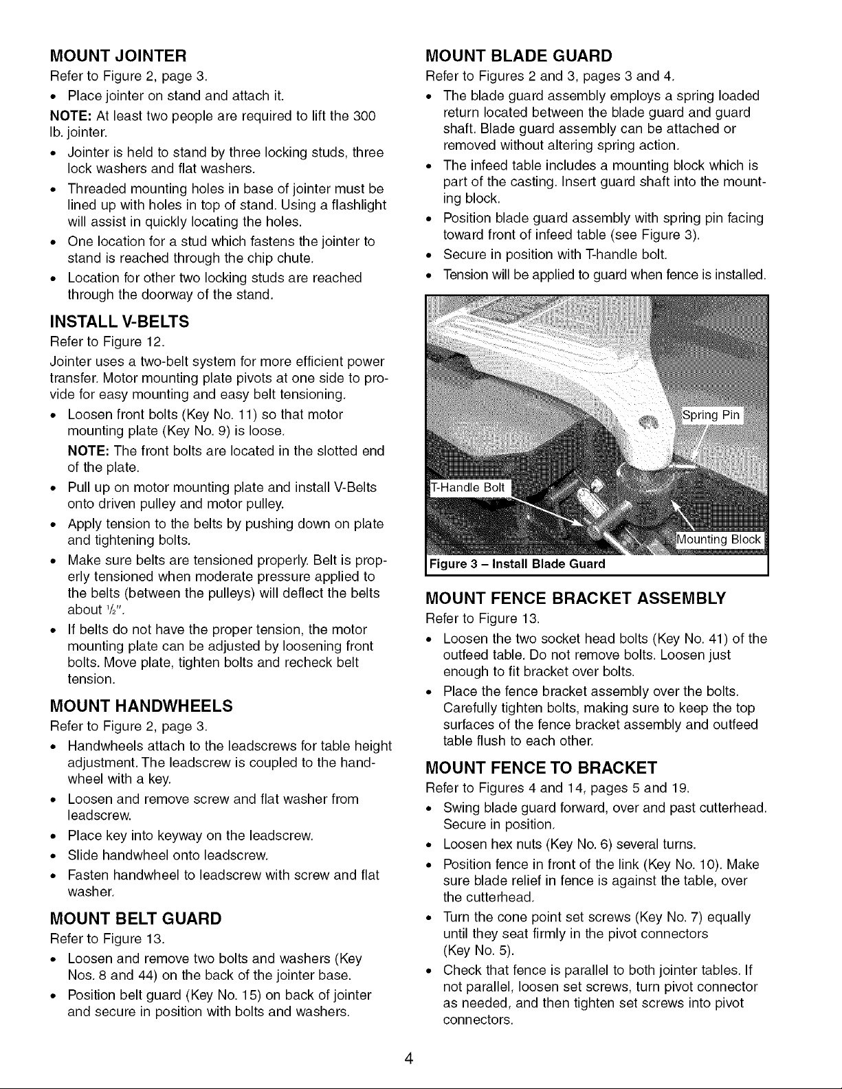
JOINTER INSTALLATION
Refer to Figure 2.
Before jointer or stand are assembled, a suitable loca-
tion should be chosen. The jointer and jointer stand
weigh approximately 400 Ibs when completely assem-
bled. They should be assembled on location.
• Jointer needs to be set on a flat, level surface.
• Make sure there is ample room on either side of
jointer to accommodate desired workpiece size.
• Good lighting and correct power supply are also
required for a proper work area.
• Place stand in its designated spot. Door panel for
access to motor is on back side.
.._e_Blade Guard Assembly
T-Handle Bolt
\
Key
Handwheel
Screw
Flat Washer
Lock Washer
Locking Stud
=igure 2 - Jointer Assembly
MOUNT JOINTER
Refer to Figure 2, page 3.
• Place jointer on stand and attach it.
NOTE: At least two people are required to lift the 300
lb. jointer.
• Jointer is held to stand by three locking studs, three
lock washers and flat washers.
• Threaded mounting holes in base of jointer must be
lined up with holes in top of stand. Using a flashlight
will assist in quickly locating the holes.
• One location for a stud which fastens the jointer to
stand is reached through the chip chute.
• Location for other two locking studs are reached
through the doorway of the stand.
INSTALL V-BELTS
Refer to Figure 12.
Jointer uses a two-belt system for more efficient power
transfer. Motor mounting plate pivots at one side to pro-
vide for easy mounting and easy belt tensioning.
• Loosen front bolts (Key No. 11) so that motor
mounting plate (Key No. 9) is loose.
NOTE: The front bolts are located in the slotted end
of the plate.
• Pull up on motor mounting plate and install V-Belts
onto driven pulley and motor pulley.
• Apply tension to the belts by pushing down on plate
and tightening bolts.
• Make sure belts are tensioned properly. Belt is prop-
erly tensioned when moderate pressure applied to
the belts (between the pulleys) will deflect the belts
about '/2".
• If belts do not have the proper tension, the motor
mounting plate can be adjusted by loosening front
bolts. Move plate, tighten bolts and recheck belt
tension.
MOUNT HANDWHEELS
Refer to Figure 2, page 3.
• Handwheels attach to the leadscrews for table height
adjustment. The leadscrew is coupled to the hand-
wheel with a key.
• Loosen and remove screw and flat washer from
leadscrew.
• Place key into keyway on the leadscrew.
• Slide handwheel onto leadscrew.
• Fasten handwheel to leadscrew with screw and flat
washer.
MOUNT BELT GUARD
Refer to Figure 13.
• Loosen and remove two bolts and washers (Key
Nos. 8 and 44) on the back of the jointer base.
• Position belt guard (Key No. 15) on back of jointer
and secure in position with bolts and washers.
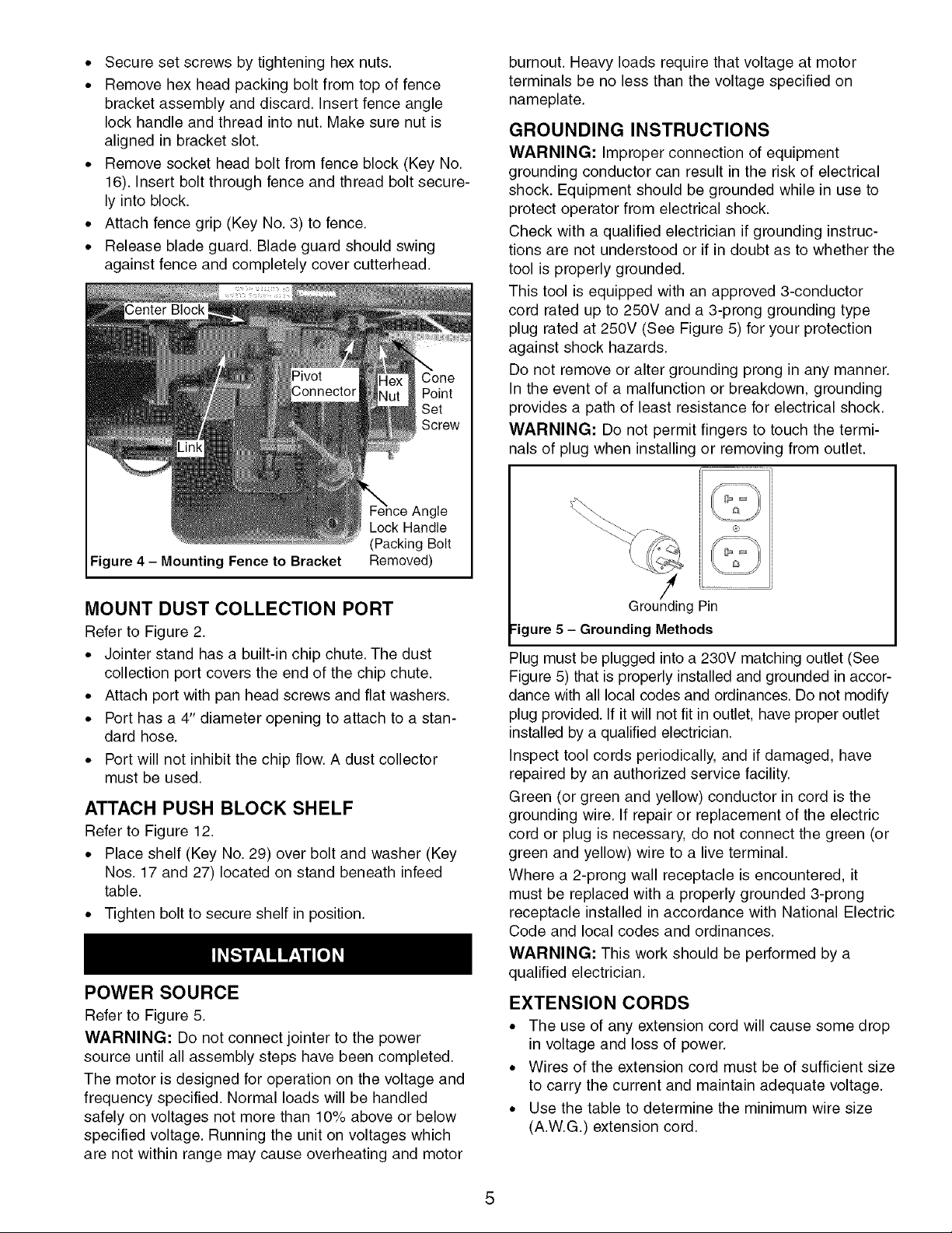
MOUNT BLADE GUARD
Refer to Figures 2 and 3, pages 3 and 4.
• The blade guard assembly employs a spring loaded
return located between the blade guard and guard
shaft. Blade guard assembly can be attached or
removed without altering spring action.
• The infeed table includes a mounting block which is
part of the casting. Insert guard shaft into the mount-
ing block.
• Position blade guard assembly with spring pin facing
toward front of infeed table (see Figure 3).
• Secure in position with T-handle bolt.
• Tension will be applied to guard when fence is installed.
Figure 3 - Install Blade Guard
MOUNT FENCE BRACKET ASSEMBLY
Refer to Figure 13.
• Loosen the two socket head bolts (Key No. 41) of the
outfeed table. Do not remove bolts. Loosen just
enough to fit bracket over bolts.
• Place the fence bracket assembly over the bolts.
Carefully tighten bolts, making sure to keep the top
surfaces of the fence bracket assembly and outfeed
table flush to each other.
MOUNT FENCE TO BRACKET
Refer to Figures 4 and 14, pages 5 and 19.
• Swing blade guard forward, over and past cutterhead.
Secure in position.
• Loosen hex nuts (Key No. 6) several turns.
• Position fence in front of the link (Key No. 10). Make
sure blade relief in fence is against the table, over
the cutterhead.
• Turn the cone point set screws (Key No. 7) equally
until they seat firmly in the pivot connectors
(Key No. 5).
• Check that fence is parallel to both jointer tables. If
not parallel, loosen set screws, turn pivot connector
as needed, and then tighten set screws into pivot
connectors.
4
• Secure set screws by tightening hex nuts.
• Remove hex head packing bolt from top of fence
bracket assembly and discard. Insert fence angle
lock handle and thread into nut. Make sure nut is
aligned in bracket slot.
• Remove socket head bolt from fence block (Key No.
16). Insert bolt through fence and thread bolt secure-
ly into block.
• Attach fence grip (Key No. 3) to fence.
• Release blade guard. Blade guard should swing
against fence and completely cover cutterhead.
gle
Lock Handle
(Packing Bolt
Figure 4 - Mounting Fence to Bracket
Removed)
burnout. Heavy loads require that voltage at motor
terminals be no less than the voltage specified on
nameplate.
GROUNDING INSTRUCTIONS
WARNING: Improper connection of equipment
grounding conductor can result in the risk of electrical
shock. Equipment should be grounded while in use to
protect operator from electrical shock.
Check with a qualified electrician if grounding instruc-
tions are not understood or if in doubt as to whether the
tool is properly grounded.
This tool is equipped with an approved 3-conductor
cord rated up to 250V and a 3-prong grounding type
plug rated at 250V (See Figure 5) for your protection
against shock hazards.
Do not remove or alter grounding prong in any manner.
In the event of a malfunction or breakdown, grounding
provides a path of least resistance for electrical shock.
WARNING: Do not permit fingers to touch the termi-
nals of plug when installing or removing from outlet.
MOUNT DUST COLLECTION PORT
Refer to Figure 2.
• Jointer stand has a built-in chip chute. The dust
collection port covers the end of the chip chute.
• Attach port with pan head screws and flat washers.
• Port has a 4" diameter opening to attach to a stan-
dard hose.
• Port will not inhibit the chip flow. A dust collector
must be used.
ATTACH PUSH BLOCK SHELF
Refer to Figure 12.
• Place shelf (Key No. 29) over bolt and washer (Key
Nos. 17 and 27) located on stand beneath infeed
table.
• Tighten bolt to secure shelf in position.
POWER SOURCE
Refer to Figure 5.
WARNING: Do not connect jointer to the power
source until all assembly steps have been completed.
The motor is designed for operation on the voltage and
frequency specified. Normal loads will be handled
safely on voltages not more than 10% above or below
specified voltage. Running the unit on voltages which
are not within range may cause overheating and motor
Grounding Pin
:igure 5 - Grounding Methods
Plug must be plugged into a 230V matching outlet (See
Figure 5) that is properly installed and grounded in accor-
dance with all local codes and ordinances. Do not modify
plug provided. If it will not fit in outlet, have proper outlet
installed by a qualified electrician.
Inspect tool cords periodically, and if damaged, have
repaired by an authorized service facility.
Green (or green and yellow) conductor in cord is the
grounding wire. If repair or replacement of the electric
cord or plug is necessary, do not connect the green (or
green and yellow) wire to a live terminal.
Where a 2-prong wall receptacle is encountered, it
must be replaced with a properly grounded 3-prong
receptacle installed in accordance with National Electric
Code and local codes and ordinances.
WARNING: This work should be performed by a
qualified electrician.
EXTENSION CORDS
• The use of any extension cord will cause some drop
in voltage and loss of power.
• Wires of the extension cord must be of sufficient size
to carry the current and maintain adequate voltage.
• Use the table to determine the minimum wire size
(A.W.G.) extension cord.

• Use only 3-wire extension cords having 3-prong
grounding type plugs and 3-pole receptacles which
accept the tool plug.
• If the extension cord is worn, cut, or damaged in any
way, replace it immediately.
EXTENSION CORD LENGTH
Wire Size A.W.G.
Up to 50 ft.................................. 12
NOTE: Using extension cords over 50 ft. long is not
recommended.
MOTOR
The stand is assembled with motor and wiring installed.
The 230 Volt AC capacitor start motor has the following
specifications:
Horsepower ................................. 2
Voltage ................................... 230
Amperes .................................. 8.6
Hertz ..................................... 60
Phase .................................. Single
RPM .................................... 3450
-q
White _
White
Black Black
Figure 6 - Wiring Schematic
ELECTRICAL CONNECTIONS
Refer to Figure 6.
WARNING: All electrical connections must be per-
formed by a qualified electrician. Make sure unit is off
and disconnected from power source while motor is
mounted, connected, reconnected or anytime wiring is
inspected.
Jointer has an approved 230 volt three-conductor line
cord with a three-prong grounding type plug, and a 230
volt magnetic contactor that is prewired in the factory
(See Figure 6).
• Connect jointer to a supply circuit protected by a 20
AMP circuit breaker or time delay fuse.
OVERLOAD PROTECTION
The magnetic contactor has overload protection that
helps to prevent damage to the motor. The overload
protection will automatically turn off the magnetic con-
tactor when an overload occurs. Be sure to disconnect
jointer from power source when resetting overload pro-
tector. The protection is reset by opening the contactor
box and pressing the reset button.
CHECK CONNECTIONS
• Plug in the line cord to a 230 volt power source.
• Turn and release the emergency stop button.
• Depress the start button. The motor must rotate
counterclockwise facing shaft end.
• Depress the stop button. The motor must stop.
• Depressing the start button with the emergency stop
button pressed down must not start the motor.
• If any of the above steps do not work properly, dis-
connect jointer from power source and recheck the
connections.
6
 Loading...