

Craftsman 351217020 Owner’s Manual
Operator's Manual
15"
PLANER
Model No.
351.217020
CAUTION: Read and follow
all Safety Rules and Operating
Instructions before First Use
of this Product. Keep this
manual with tool.
Sears, Roebuck and Co., Hoffman Estates, IL 60179 U.S.A.
www.sears.com/craftsman
21703.01 Draft (05/11/05)
Warranty.................................... 2
SafetyRules............................... 2-3
Unpacking.................................. 3
Assembly................................. 3-4
Installation................................. 4-5
KnowYourPlaner............................. 6
Operation................................ 6-11
Maintenance............................. 11-14
Troubleshooting............................. 15
PartsIllustrationandList................... 18-23
FULL ONE YEAR WARRANTY
If this product fails due to a defect in material or workman-
ship within one year from the date of purchase, Sears will
at its option repair or replace it free of charge. Contact
your nearest Sears Service Center (1-800-4-MY-HOME)
to arrange for product repair, or return this product to
place of purchase for replacement.
If this product is used for commercial or rental purpos-
es, this warranty will apply for 90 days from the date of
purchase.
This warranty applies only while this product is used in
the United States.
This warranty gives you specific legal rights, and you
may also have other rights which vary from state to state.
Sears, Roebuck and Co., Dept. 817WA, Hoffman
Estates, IL 60179
WARNING: For your own safety, read all of the rules
and precautions before operating tool.
CAUTION: Always follow proper operating procedures
as defined in this manual even if you are familiar with
use of this or similar tools. Remember that being care-
less for even a fraction of a second can result in severe
personal injury.
BE PREPARED FOR JOB
• Wear proper apparel. Do not wear loose clothing,
gloves, neckties, rings, bracelets or other jewelry
which may get caught in moving parts of machine.
• Wear protective hair covering to contain long hair.
• Wear safety shoes with non-slip soles.
• Wear safety glasses complying with United States
ANSI Z87.1. Everyday glasses have only impact
resistant lenses. They are NOT safety glasses.
• Wear face mask or dust mask if operation is dusty.
• Be alert and think clearly. Never operate power tools
when tired, intoxicated or when taking medications
that cause drowsiness.
PREPARE WORK AREA FOR JOB
• Keep work area clean. Cluttered work areas invite
accidents.
• Do not use power tools in dangerous environments.
• Do not use power tools in damp or wet locations. Do
not expose power tools to rain.
• Work area should be properly lighted.
• Proper electrical receptacle should be available for
tool. Three prong plug should be plugged directly
into properly grounded, three-prong receptacle.
• Extension cords should have a grounding prong and
the three wires of the extension cord should be of
the correct gauge.
• Keep visitors at a safe distance from work area.
• Keep children out of workplace. Make workshop child-
proof. Use padlocks, master switches or remove switch
keys to prevent any unintentional use of power tools.
TOOL SHOULD BE MAINTAINED
• Always unplug tool prior to inspection.
• Consult manual for specific maintaining and adjust-
ing procedures.
• Keep tool lubricated and clean for safest operation.
• Remove adjusting tools. Form habit of checking to
see that adjusting tools are removed before switch-
ing machine on.
• Keep all parts in working order. Check to determine
that the guard or other parts will operate properly
and perform their intended function.
• Check for damaged parts. Check for alignment of
moving parts, binding, breakage, mounting and any
other condition that may affect a tool's operation.
• A guard or other part that is damaged should be
properly repaired or replaced. Do not perform
makeshift repairs. (Use parts list provided to order
replacement parts.)
KNOW HOW TO USE TOOL
• Use right tool for job. Do not force tool or attachment
to do a job for which itwas not designed.
• Disconnect tool when changing blades.
• Avoid accidental start-up. Make sure that the switch
key is in the OFF position before plugging in.
• Do not force tool. It will work most efficiently at the
rate for which it was designed.
• Keep hands away from moving parts and cutting
surfaces.
• Never leave tool running unattended. Turn the power
off and do not leave tool until it comes to a complete
stop.
• Do not overreach. Keep proper footing and balance.
© Sears, Roebuck and Co. 2
• Never stand on tool. Serious injury could occur if tool is
tipped or if blade is unintentionally contacted.
• Know your tool. Learn the tool's operation, applica-
tion and specific limitations.
• Use recommended accessories (refer to page 19).
Use of improper accessories may cause risk of
injury to persons.
• Handle workpiece correctly. Protect hands from pos-
sible injury.
• Turn machine off if it jams. Blade jams when it digs
too deeply into workpiece. (Motor force keeps it
stuck in the work.)
• Always keep drive, cutterhead and blade guards in
place and in proper operating condition.
• Feed work into blade or cutter against direction of
rotation.
CAUTION: Think safety! Safety is a combination of
operator common sense and alertness at all times
when tool is being used.
WARNING: Do not attempt to operate tool until it is
completely assembled according to the instructions.
Check for shipping damage. If damage has occurred, a
claim must be filed with carrier. Check for complete-
ness. Immediately report missing parts to dealer.
Additional parts which need to be fastened to the planer
should be located and accounted for before assembling.
Planer is shipped assembled except for the following:
two table extensions, handwheel handle, chip chute, two
roller gauge blocks, blade height gauge, roller assembly,
two roller brackets, floor leveling feet and hardware bag.
Hardware bag (Part No. 23516.00) includes:
• 8-1.25 x 25mm Socket Head Bolt (4)
• 8-1.25 x 12mm Socket Head Bolt (3)
• 8mm Flat Washer (7)
• 8mm LockWasher (4)
• 6-1.0 x 12mm Socket Head Bolt (4)
• 6-1.0 x 12mm Hex Head Bolt (3)
• 6mm Flat Washer (6)
• 6-1.0mm Hex Nut (3)
IMPORTANT: Table, table rollers and cutterhead are
coated with a protectant. To ensure proper fit and oper-
ation, remove coating. Coating is easily removed with
mild solvents, such as mineral spirits, and a soft cloth.
Use caution when cleaning the cutterhead, as the
blades are very sharp. Avoid getting solution on paint or
any of the rubber or plastic parts. Solvents may deterio-
rate these finishes. Use soap and water on paint, plas-
tic or rubber components. After cleaning, cover all
exposed surfaces with a light coating of oil. Paste wax
is recommended for table top.
WARNING: Never use highly volatile solvents. Non-
flammable solvents are recommended to avoid possible
fire hazard.
WARNING: Do not attempt assembly if parts are
missing. Use this manual to order replacement parts.
PLANER INSTALLATION
Before planer is assembled, a suitable location should
be chosen. The planer weighs approximately 500 Ibs
when completely assembled. Planer should be assem-
bled on location.
• Planer needs to be set on a flat, level surface. This
improves stability, accuracy and prevents warpage
and failure of cast components and welds.
• Make sure there is ample room on both infeed and
outfeed sides of planer for moving the workpiece
through the entire cut. There must be enough room
that neither the operators nor the bystanders will
have to stand in line with the wood while using the
tool.
• Good lighting and correct power supply (230 volts)
are also required for a proper work area.
• Place planer in its designated spot. Covers for
access to motor are on both front and rear sides of
stand. The planer is supplied with four lifting handles
that slide into the base on the infeed and outfeed
sides. The planer must be lifted by these handles
only and moved to the required location.
ATTACH LEVELING FEET
Refer to Figure 21, page 22.
• Required parts and hardware:
Foot (4)
10-1.5mm Hex Nut (4)
• Remove access covers (Key No. 53).
• Attach foot assemblies (Key Nos. 57 and 60) to the
cabinet (Key No. 52).
• With planer in position, check table surface length-
wise and crosswise with machinist level. Check that
all four corners are supported. Adjust foot as needed
and secure in position with hex nut.
• Replace access covers.
MOUNT HEIGHT ADJUSTMENT
HANDWHEEL HANDLE
Refer to Figure 20, page 20.
• Required parts: Handle
• Thread handle into handwheel.
• Tighten hex nut to secure handle.
MOUNT CHIP CHUTE
Refer to Figure 20, page 20.
• Required parts and hardware:
Chip Chute
6-1.0 x 12mm Hex Head Bolt (3)
6mm Flat Washer (6)
6-1.0mm Hex Nut (3)
8-1.25 x 12mm Socket Head Bolt (3)
8mm Flat Washer (3)
• Position chip chute on chipbreaker cover (Key No. 52)
so that the slots on chip chute and chipbreaker cover
are aligned and slots on chip chute and holes on the
roller case are aligned.
• Secure chip chute to chipbreaker cover using three
hex head bolts, six flat washers and three hex nuts.
• Secure chip chute to roller case (Key No. 1) using
three socket head bolts and three flat washers.
MOUNT REAR RETURN ROLLER
Refer to Figure 20, page 20.
• Required parts and hardware:
Roller Assembly
Roller Bracket (2)
6-1.0 x 12mm Socket Head Bolt (4)
• Attach one roller bracket(Key No. 55) to rollercase
(Key No. 1) using two socket head bolts (Key No. 58).
• Insert one end of roller assembly (Key No. 56) into
bracket attached in previous step.
• Insert the other end of roller assembly into remaining
bracket and attach to roller case.
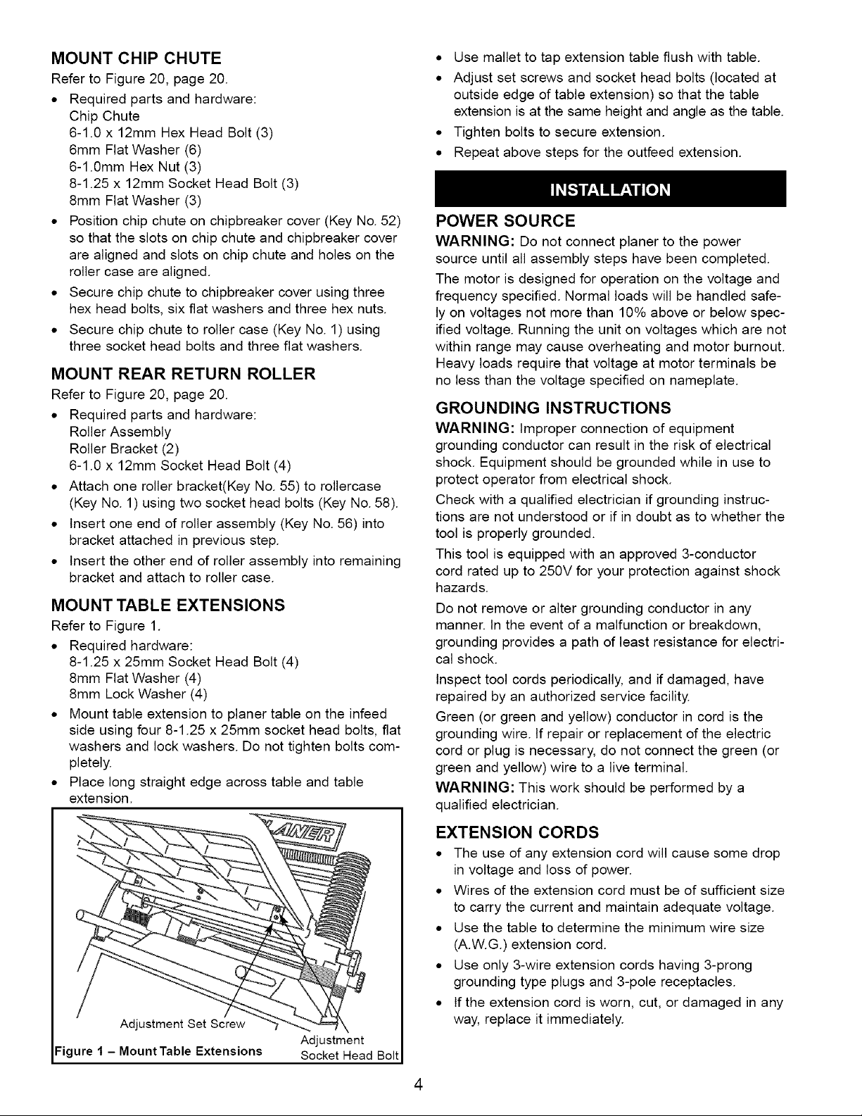
MOUNT TABLE EXTENSIONS
Refer to Figure 1.
• Required hardware:
8-1.25 x 25mm Socket Head Bolt (4)
8mm Flat Washer (4)
8mm Lock Washer (4)
• Mount table extension to planer table on the infeed
side using four 8-1.25 x 25mm socket head bolts, flat
washers and lock washers. Do not tighten bolts com-
pletely.
• Place long straight edge across table and table
extension.
• Use mallet to tap extension table flush with table.
• Adjust set screws and socket head bolts (located at
outside edge of table extension) so that the table
extension is at the same height and angle as the table.
• Tighten bolts to secure extension.
• Repeat above steps for the outfeed extension.
POWER SOURCE
WARNING: Do not connect planer to the power
source until all assembly steps have been completed.
The motor is designed for operation on the voltage and
frequency specified. Normal loads will be handled safe-
ly on voltages not more than 10% above or below spec-
ified voltage. Running the unit on voltages which are not
within range may cause overheating and motor burnout.
Heavy loads require that voltage at motor terminals be
no less than the voltage specified on nameplate.
GROUNDING INSTRUCTIONS
WARNING: Improper connection of equipment
grounding conductor can result in the risk of electrical
shock. Equipment should be grounded while in use to
protect operator from electrical shock.
Check with a qualified electrician if grounding instruc-
tions are not understood or if in doubt as to whether the
tool is properly grounded.
This tool is equipped with an approved 3-conductor
cord rated up to 250V for your protection against shock
hazards.
Do not remove or alter grounding conductor in any
manner. In the event of a malfunction or breakdown,
grounding provides a path of least resistance for electri-
cal shock.
Inspect tool cords periodically, and if damaged, have
repaired by an authorized service facility.
Green (or green and yellow) conductor in cord is the
grounding wire. If repair or replacement of the electric
cord or plug is necessary, do not connect the green (or
green and yellow) wire to a live terminal.
WARNING: This work should be performed by a
qualified electrician.
Adjustment Set Screw
Figure I - MountTable Extensions
I
Adjustment
Socket Head Bolt
EXTENSION CORDS
• The use of any extension cord will cause some drop
in voltage and loss of power.
• Wires of the extension cord must be of sufficient size
to carry the current and maintain adequate voltage.
• Use the table to determine the minimum wire size
(A.W.G.) extension cord.
• Use only 3-wire extension cords having 3-prong
grounding type plugs and 3-pole receptacles.
• If the extension cord is worn, cut, or damaged in any
way, replace it immediately.
4
EXTENSION CORD LENGTH
Wire Size A.W.G.
Up to 50 ft.................................. 12
NOTE: Using extension cords over 50 ft. long is not
recommended.
MOTOR
The planer is assembled with motor and wiring
installed. The 230 Volt AC capacitor start motor has the
following specifications:
Horsepower ................................. 3
Voltage ................................... 230
Amperes ................................. 16.5
Hertz ..................................... 60
Phase .................................. Single
RPM .................................... 3450
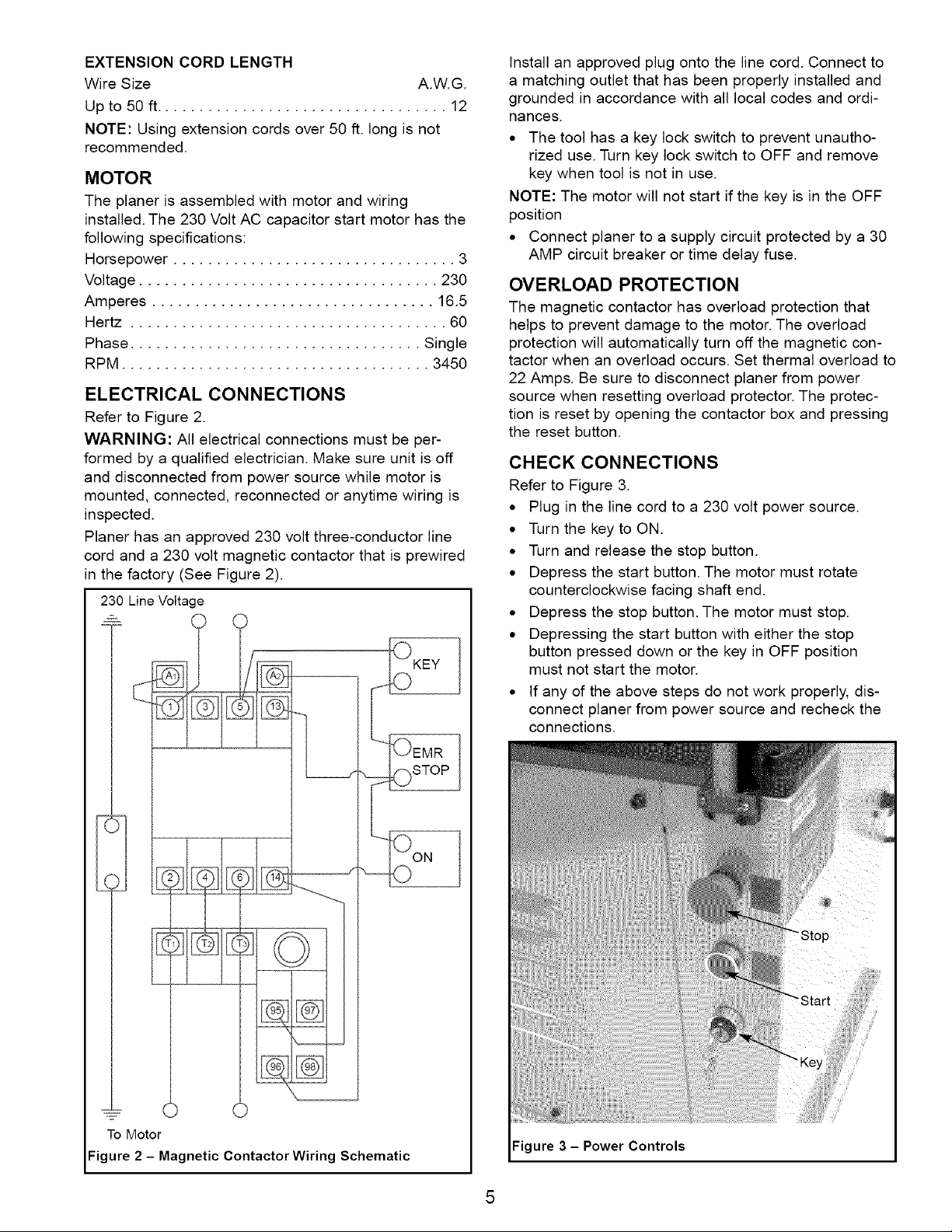
ELECTRICAL CONNECTIONS
Refer to Figure 2.
WARNING: All electrical connections must be per-
formed by a qualified electrician. Make sure unit is off
and disconnected from power source while motor is
mounted, connected, reconnected or anytime wiring is
inspected.
Planer has an approved 230 volt three-conductor line
cord and a 230 volt magnetic contactor that is prewired
in the factory (See Figure 2).
230 Line Voltage
Install an approved plug onto the line cord. Connect to
a matching outlet that has been properly installed and
grounded in accordance with all local codes and ordi-
nances.
• The tool has a key lock switch to prevent unautho-
rized use. Turn key lock switch to OFF and remove
key when tool is not in use.
NOTE: The motor will not start if the key is in the OFF
position
• Connect planer to a supply circuit protected by a 30
AMP circuit breaker or time delay fuse.
OVERLOAD PROTECTION
The magnetic contactor has overload protection that
helps to prevent damage to the motor. The overload
protection will automatically turn off the magnetic con-
tactor when an overload occurs. Set thermal overload to
22 Amps. Be sure to disconnect planer from power
source when resetting overload protector. The protec-
tion is reset by opening the contactor box and pressing
the reset button.
CHECK CONNECTIONS
Refer to Figure 3.
• Plug in the line cord to a 230 volt power source.
• Turn the key to ON.
• Turn and release the stop button.
• Depress the start button. The motor must rotate
counterclockwise facing shaft end.
• Depress the stop button. The motor must stop.
• Depressing the start button with either the stop
button pressed down or the key in OFF position
must not start the motor.
• If any of the above steps do not work properly, dis-
connect planer from power source and recheck the
connections.
To Motor
Figure 2 - Magnetic Contactor Wiring Schematic
Figure 3 - Power Controls
/
/
/
3
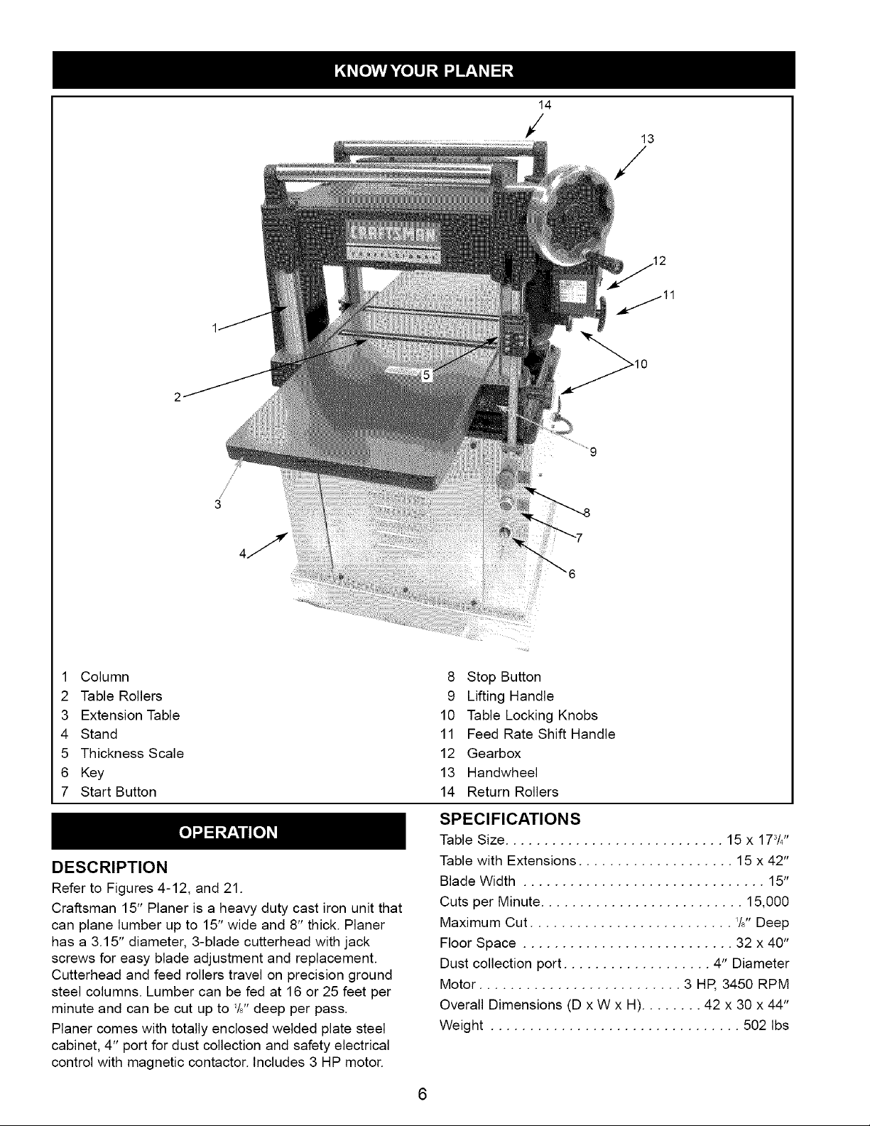
1 Column
2 Table Rollers
3 Extension Table
4 Stand
5 Thickness Scale
6 Key
7 Start Button
DESCRIPTION
Refer to Figures 4-12, and 21.
Craftsman 15" Planer is a heavy duty cast iron unit that
can plane lumber up to 15" wide and 8" thick. Planer
has a 3.15" diameter, 3-blade cutterhead with jack
screws for easy blade adjustment and replacement.
Cutterhead and feed rollers travel on precision ground
steel columns. Lumber can be fed at 16 or 25 feet per
minute and can be cut up to '/J' deep per pass.
Planer comes with totally enclosed welded plate steel
cabinet, 4" port for dust collection and safety electrical
control with magnetic contactor. Includes 3 HP motor.
8 Stop Button
9 Lifting Handle
10 Table Locking Knobs
11 Feed Rate Shift Handle
12 Gearbox
13 Handwheel
14 Return Rollers
SPECIFICATIONS
Table Size ............................ 15 x 173/4"
Table with Extensions .................... 15 x 42"
Blade Width ............................... 15"
Cuts per Minute .......................... 15,000
Maximum Cut .......................... 76"Deep
Floor Space ........................... 32 x 40"
Dust collection port ................... 4" Diameter
Motor .......................... 3 HP, 3450 RPM
Overall Dimensions (D x W x H)........ 42 x 30 x 44"
Weight ................................ 502 Ibs
6
Planing refers to the sizing of lumber to a desired thick-
ness while creating a level surface parallel to the oppo-
site size of the board. Depth of cut is the term used to
indicate how deep the blades will cut into the workpiece.
OPERATION SAFETY RULES
WARNING: Operation of any power tool can result in
foreign objects being thrown into eyes which can result
in severe eye damage. Always wear safety goggles
complying with United States ANSI Z87.1 (shown on
package) before commencing power tool operation.
CAUTION: Always observe the following safety
precautions:
• Know general power tool safety. Make sure all
precautions are understood (See pages 2, 3 and 7).
• Whenever adjusting or replacing any parts on planer,
turn switch off and remove plug from power source.
• Make sure the cutterhead and chipbreaker covers
are properly attached and securely fastened.
• Make sure all moving parts are free from interference.
• Always wear eye protection or face shield.
• Make sure blades are aligned and properly attached
to cutterhead.
• Do not plug in planer unless switch is in OFF posi-
tion. After turning switch on, allow planer to come to
full speed before operating.
• Keep hands clear of all moving parts.
• Do not force cut. Slowing or stalling will overheat
motor. Allow automatic feed to function properly.
• Use quality lumber. Blades last longer and cuts are
smoother with good quality wood.
• Do not perform planing operations on material short-
er than 18", narrower than 3/4",or less than 'tZ' thick.
• Never make planing operation on material wider than
15" or cut deeper than W'
• Always keep cutterhead and blade guards in proper
working condition.
• Maintain the proper relationships of infeed and out-
feed table surfaces and cutterhead blade path.
• Do not back the work toward the infeed table.
• Support the workpiece adequately at all times during
operation; maintain control of the workpiece.
• Take precautions against kickback. Do not permit
anyone to stand or cross in line of cutterhead's rota-
tion. Kickback or thrown debris will travel in this
direction.
• Turn switch off and disconnect power whenever plan-
er is not in use.
• Replace or sharpen blades as they become damaged
or dull.
• Keep planer maintained. Follow maintenance
instructions (See pages 11-14).
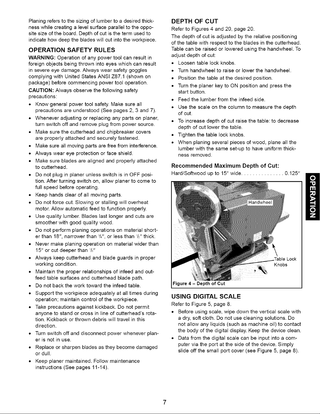
DEPTH OF CUT
Refer to Figures 4 and 20, page 20.
The depth of cut is adjusted by the relative positioning
of the table with respect to the blades in the cutterhead.
Table can be raised or lowered using the handwheel. To
adjust depth of cut:
• Loosen table lock knobs.
• Turn handwheel to raise or lower the handwheel.
• Position the table at the desired position.
• Turn the planer key to ON position and press the
start button.
• Feed the lumber from the infeed side.
• Use the scale on the column to measure the depth
of cut.
• To increase depth of cut raise the table: to decrease
depth of cut lower the table.
• Tighten the table lock knobs.
• When planing several pieces of wood, plane all the
lumber with the same set-up to have uniform thick-
ness removed.
Recommended Maximum Depth of Cut:
Hard/Softwood up to 15" wide ............... 0.125"
Lock
Knobs
Figure 4 - Depth of Cut
USING DIGITAL SCALE
Refer to Figure 5, page 8.
• Before using scale, wipe down the vertical scale with
a dry, soft cloth. Do not use cleaning solutions. Do
not allow any liquids (such as machine oil) to contact
the body of the digital display. Keep the device clean.
• Data from the digital scale can be input into a com-
puter via the port at the side of the device. Simply
slide off the small port cover (see Figure 5, page 8).
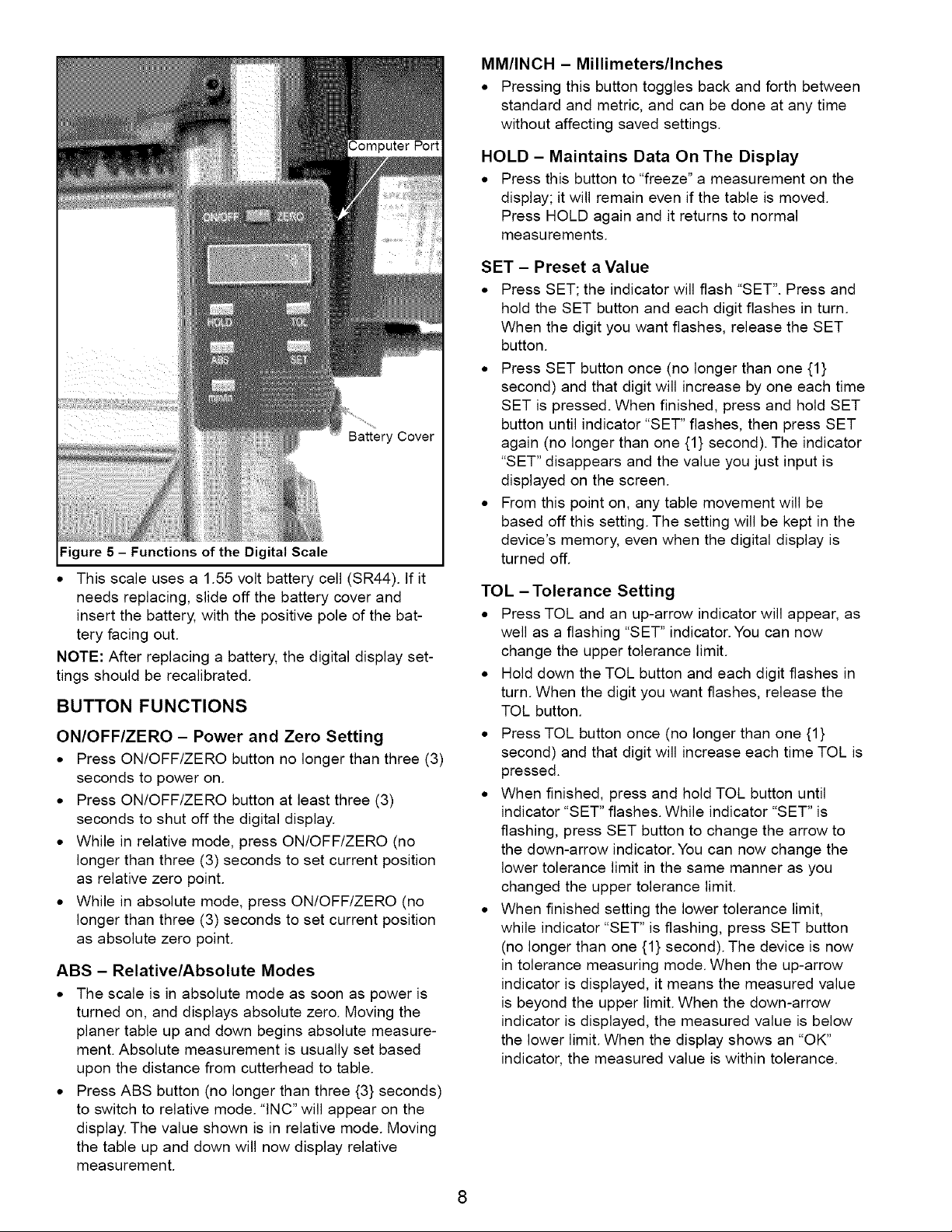
Battery Cover
Figure5 - Functions of the Digital Scale
• This scale uses a 1.55 volt battery cell (SR44). tf it
needs replacing, slide off the battery cover and
insert the battery, with the positive pole of the bat-
tery facing out.
NOTE: After replacing a battery, the digital display set-
tings should be recalibrated.
BUTTON FUNCTIONS
ON/OFF/ZERO - Power and Zero Setting
• Press ON/OFF/ZERO button no longer than three (3)
seconds to power on.
• Press ON/OFF/ZERO button at least three (3)
seconds to shut off the digital display.
• While in relative mode, press ON/OFF/ZERO (no
longer than three (3) seconds to set current position
as relative zero point.
• While in absolute mode, press ON/OFF/ZERO (no
longer than three (3) seconds to set current position
as absolute zero point.
ABS - Relative/Absolute Modes
• The scale is in absolute mode as soon as power is
turned on, and displays absolute zero. Moving the
planer table up and down begins absolute measure-
ment. Absolute measurement is usually set based
upon the distance from cutterhead to table.
• Press ABS button (no longer than three {3} seconds)
to switch to relative mode. "INC" will appear on the
display. The value shown is in relative mode. Moving
the table up and down will now display relative
measurement.
MM/INCH - Millimeters/Inches
• Pressing this button toggles back and forth between
standard and metric, and can be done at any time
without affecting saved settings.
HOLD - Maintains Data On The Display
• Press this button to "freeze" a measurement on the
display; it will remain even if the table is moved.
Press HOLD again and it returns to normal
measurements.
SET - Preset a Value
• Press SET; the indicator will flash "SET". Press and
hold the SET button and each digit flashes in turn.
When the digit you want flashes, release the SET
button.
• Press SET button once (no longer than one {1}
second) and that digit will increase by one each time
SET is pressed. When finished, press and hold SET
button until indicator "SET" flashes, then press SET
again (no longer than one {1} second). The indicator
"SET" disappears and the value you just input is
displayed on the screen.
• From this point on, any table movement will be
based off this setting. The setting will be kept in the
device's memory, even when the digital display is
turned off.
TOL - Tolerance Setting
• Press TOL and an up-arrow indicator will appear, as
well as a flashing "SET" indicator. You can now
change the upper tolerance limit.
• Hold down the TOL button and each digit flashes in
turn. When the digit you want flashes, release the
TOL button.
• Press TOL button once (no longer than one {1}
second) and that digit will increase each time TOL is
pressed.
• When finished, press and hold TOL button until
indicator "SET" flashes. While indicator "SET" is
flashing, press SET button to change the arrow to
the down-arrow indicator. You can now change the
lower tolerance limit in the same manner as you
changed the upper tolerance limit.
• When finished setting the lower tolerance limit,
while indicator "SET" is flashing, press SET button
(no longer than one {1} second). The device is now
in tolerance measuring mode. When the up-arrow
indicator is displayed, it means the measured value
is beyond the upper limit. When the down-arrow
indicator is displayed, the measured value is below
the lower limit. When the display shows an "OK"
indicator, the measured value is within tolerance.
8
 Loading...