

Craftsman 351215200 Owner’s Manual

Operator's Manual
4 x 36" Belt
SANDER
8" Disc
Model No.
351.21 5200
CAUTION: Read and follow
all Safety Rules and Operating
Instructions before First Use
of this Product. Keep this
manual with tool.
Sears, Roebuck and Co., Hoffman Estates, IL 60179 U.S.A.
_II_W. $ Ba rS.CO _cr a_s man
23738.01 Draft (06/16/05)

Warranty ......................................... 2
Safety Rules ...................................... 2
Unpacking ....................................... 3
Assembly ...................................... 3-4
Installation ...................................... 4-5
Operation ...................................... 6-8
Maintenance ..................................... 9
Troubleshooting ................................... 9
Parts [llustrationand List ........................ 10-13
Espafiol ...................................... 14-23
ONE-YEAR FULL WARRANTY ON CRAFTSMAN TOOL
I_thLsCraftsman tool fails due to a defect inmatedal or
workmanship within one year from the date of pumhase CALL
t-80O-4-MY-HOME® TO ARRANGE FOR FREE REPAIR.
If this tool is used for commercial or rents1 purposes, this war-
ranty will apply for only ninety days from the date of purchase.
This warranty applies only while this tool is in the United
States.
This warranty givesyou specific legal rights and you may also
have other dghts, which vary, from state to state.
Sears, Roebuck and Co., Dept. 817WA, Hoffman Estates,
IL 60179
WARNING: For your own safety, read all af the instructions
and precautions before operating tool.
CAUTION: Always follow proper operating procedures as
defined in this manual even ifyou are familiarwith use of this
or similartools. Remember that being careless for even a
fraction of a second can result in severe personal Injury.
BE PREPARED FOR JOB
• Wear proper apparel, Do not wear loose clothing,gloves,
neckties, rings, bracelets or other jewelry which may get
caught in moving parts of machine.
• Wear protective hair c=Overingto contain long hair.
• Wear safety shoes with non-slipsoles.
• Wear safety glasses complyingwith United States ANSI
Z87.1. Everyday glasses have only impact resistant lenses.
They are NOT safety glasses.
• Wear face mask or dust mask if operation is dusty.
• Be alert and think clearly. Never operate power tools when
tired, intoxicated or when taking medications that cause
drowsiness.
PREPARE WORK AREA FOR JOB
• Keepwork area clean. Cluttered work areas (nvfteaco_denfs.
• Do notuse power tools in dangerous environments. Do not
use power tools in damp or wet locations. Do not expose
power tools to rain.
• Work area should be properly lighted.
• Proper electrical receptaale should be availablefor tool.
Three-prong plug should be plugged directly into properly
grounded, three-prong receptacle.
• Extension cords should have a groundingprong andme three
wires of the extension cordshouldbe of the correctgauge.
• Keep visitors at a safe distance from work area.
• Keep children out of workplace. Make workshop shildproof.
Use padlocks, master switches or remove switch keys to
prevent any unintentional use of power tools.
TOOL SHOULD BE MAINTAINED
• Always unplug tool prior to inspection.
• Consult manual for specific maintaining and adjusting
procedures.
• Keep tool lubricated and cleanfor safest operation.
• Remove adjusting tools. Form habit of checking to see that
adjusting tools are removed before switchingmachine on.
• Keep all parts in working order. Check to determine that the
guard or other parts will operate properly and perform their
intended function.
• Check for damaged parts. Check for alignment of moving
parts, binding, breakage, mounting and any other condition
that may affect a tool's operation.
• A guard or other part that is damaged should be properly
repaired or replaced. Do not perform makeshift repairs.
(Usa parts list provided to order replacement parts.)
KNOW HOWTO USE TOOL
• Use right teal for job. Do notforce toolor attachment to do
a job for which it was not designed.
• Disconnect tool when changing belt or abrasive disc.
• Avoid accidental start-up. Make sure that the tool is in the
"OFF" position before plugging in.
• Do not force tool. It will work most efficiently at the rate for
which it was designed.
• Keep hands away from moving parts and sanding surfaces.
• Never leave tool running unattanded.Tum the power off
and do not leave tool until it comes to a complete stop.
• Do not overreach. Keep proper footing and balance.
• Never stand on tool. Serious injury could occur if tool is
tipped or ff belt or disc are unintentionatly contacted.
• Know your tool Learn the tool's opera, on, application and
specific limitations.
• Use recommended accessories (rarer to page 13). Use of
improper accessories may cause risk of injury to persons.
• Handle the workpiece correctly.Protect hands from possi-
ble injury.
• Turn machine off if it jams. Belt jams when itdigs too
deeply into workpiecs. (Motor force keeps itstuck inthe
work.)
Support workpieee with miter gauge, belt platen or work
table.
• Maintain '/_" maximum clearance between table and sand-
ing belt or disc.
CAUTION: Think safety! Safety is a combination ofoperator
common sense and alertness at all times when tool is being
used.
WARNING: Do not attempt to operate tool until itis oom-
plete)y assembled according tothe instructions.
© Sears, Roebuck and Co. 2
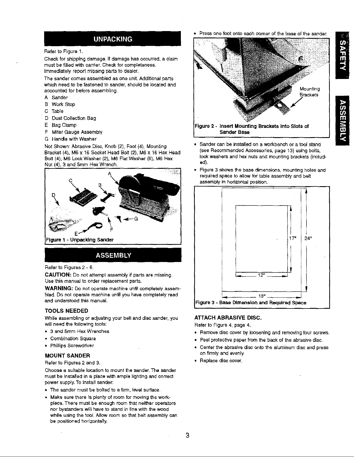
Refer to Figure 1,
Check for shipping damage. If damage has occurred, a claim
must be filled with carrier. Check for completeness,
Immediately report missing parts to dealer.
The sander comes assembled as one unit. Additional parts
which need to be fastened to sander, should be located and
accounted for before assembling.
A Sander
B Work Stop
C Table
D Dust Collection Bag
E Bag Clamp
F Miter Gauge Assembly
G Handle with Washer
Not Shown: Abrasive Disc, Knob (2), Foot (4), Mounting
Bracket (4), M6 x 16 Socket Head Bolt (2). M6 x 16 Hex Head
Bolt (4), M6 Look Washer (2), M6 Flat Washer (6), M6 Hex
Nut (4). 3 and 5mm Hsx Wrench.
A
C
• Press one foot onto each comer of the base of the sander.
Mounting
Brackets
Figure 2 - In_rl Mounting Brackets into Slots of
Sander Base
• Sander can be installed on a workbench or a tool stand
(see Recommended Accessories, page 13) usir_g bolts,
lock washers and hex nuts and mounting brackets (includ-
ed).
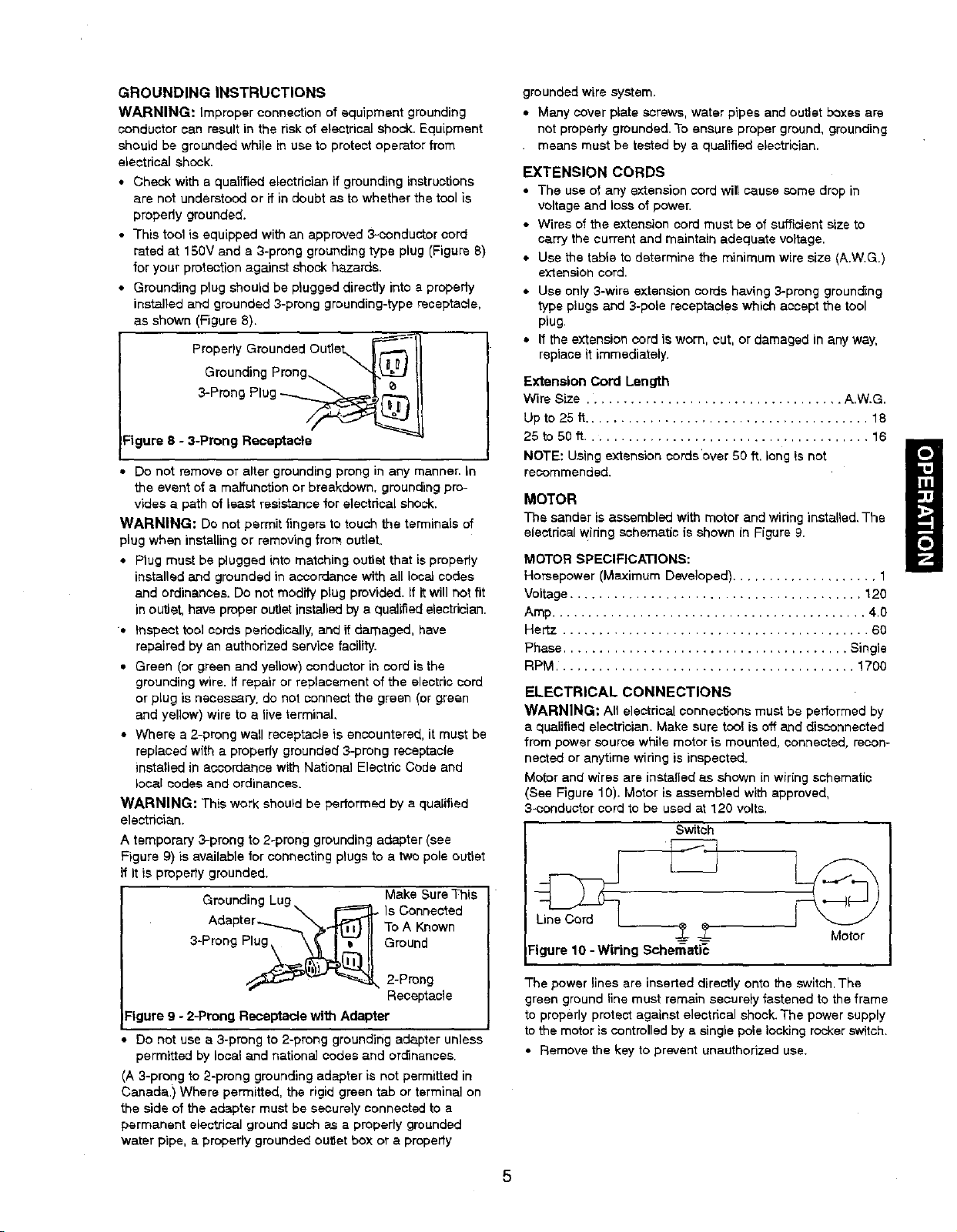
• Figure 3 shows the base dimensions, mounting holes and
required space to allow for table assembly and belt
assembly in horizontal position.
I
!
-'It
Figure 1 - Unpacking Sander
Refer to Figures 2 - 6.
CAUTION: Do not attempt assembly if parts are missing.
Use this manual to order replacement parts.
WARNING: Do notoperate machine untilcompletely assem-
bled. Do not operate machine until you have completely read
and understood this manual.
TOOLS NEEDED
While assembling or adjustingyour belt and discsander, you
will need the following tools:
• 3 and 5ram Rex Wrenches
• Combination Square
• Phillips Screwdriver
MOUNT SANDER
Refer to Figures 2 and 3.
Choose a suitable location to mount the sander,The sander
must be installed in a place with ample lighting and correct
power supply. To install sander:
• The sander must be bolted to a firm, level surface.
• Make sure there is plenty of room for moving the work-
piece.There must be enough room that neither operators
nor bystanders will have to stand in line with the wood
whila using the tool. Allow room so that belt assembly can
be positioned horizontally,
7" 24"
I_ !2"
18"
Figure 3 - Base Dimension and Required Space
ATTACH ABRASIVE DISC.
Refer to Figure 4, page 4.
• Remove disc cover by loosening and removing four screws.
• Peel protective paper from the beck of the abrasive disc.
• Center the abrasive disc onto the aluminum disc and press
on firmly and evenly.
• Replace disc cover.
3
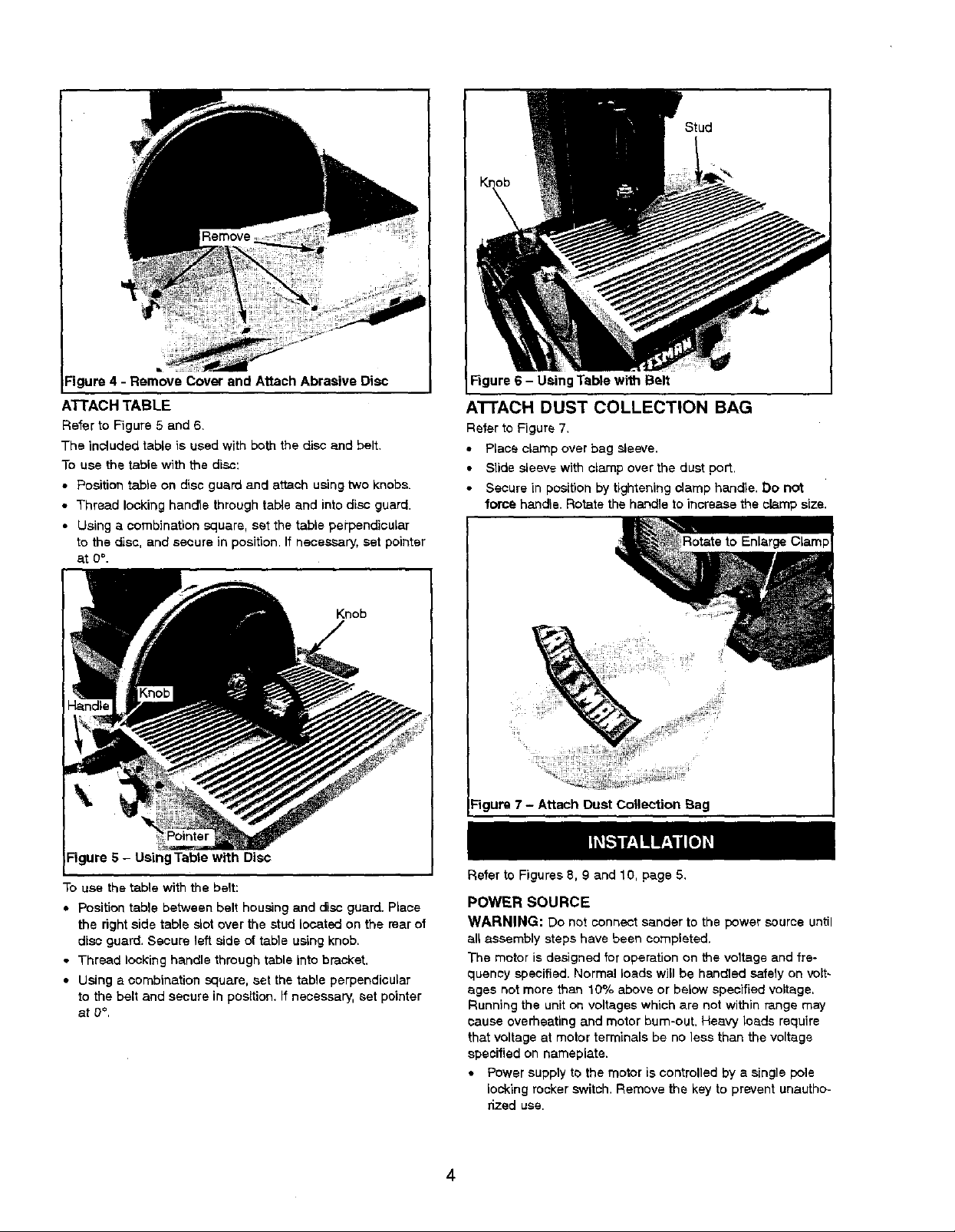
Figure 4 - Remove Cover and Attach Abrasive Disc
ATTACH TABLE
Refer to Figure 5 and 6.
The included table is used with both the disc and belt.
To use the table with the disc:
• Position table on disc guard and attach using two knobs.
• Thread locking handle through tal_e and into disc guard.
• Using a combination square, set the table perpendicular
to the disc, and secure in position.If necessary, set pointer
at 0°.
Figure 6 - Using Table with Belt
ATTACH DUST COLLECTION BAG
Refer to Figure 7,
• Place clamp over bag sleeve.
• Slide sleeve with clamp over the dust port.
Secure in position by tightening clamp handle. Do not
force handle. Rotate the handle to increase the clamp size.
_gure 7 - Attach Dust Collection Bag
Figure 5 - Using Table with Disc
To use the table with the belt:
• Position table between belt housing and disc guard. Place
the right side table slot over the stud located on the rear of
disc guard. Secure left aide of table using knob.
• Thread locking handle through table into bracket.
• Using a combination square, set the table perpendicular
to the belt and secure in position, If necessary, set pointer
at 0°,
Refer to Figures 8, 9 and 10, page 5,
POWER SOURCE
WARNING: Do not connect sander to the power source until
all assembly steps have been completed.
The motor is designed for operation on the voltage and fre-
quency specified. Normal loads will be handled safely on volt-
ages not more than 10% above or below specified voltage,
Running the uniton voltageswhich are not within range may
cause overheating and motor bum-out, Heavy loads require
that voltageat motor termlnals be no less than the voltage
specified on nameplate.
• Power supply to the motor is controlled by s single pole
locking rocker switch. Remove the key to prevent unautho-
rized use.
4
GROUNDING INSTRUCTIONS
WARNING: Improper oonnsction of equipment grounding
conductor can resultin the risk of electrical shock. Equipment
should be groundedwhile in use to protect operator from
electrical shock.
• Check with a qualified electrician if grounding instructions
are not understood or if in doubt as to whether the tool is
properly grounded.
• This tool is equipped with an approved 3-conductor cord
rated at 150V and a 3-prong grounding type plug (Figure 8)
for your protection against shock hazards.
• Grounding plug shouldbe plugged directly into a properiy
installed and grounded 3-prong grounding-type recaptacle,
as shown (Figure 8).
Properly Grounded Outlet_ _'_
Grounding Prong...
3-Prong Plug
Figure 8 - 3-Prong Receptacle
Do not remove or alter grounding prong in any manner. In
the event of a malfunction or breakdown, grounding pro-
vides a path of least resistance for electrical shock.
WARNING: Do not permit fingers to touch the terminals of
plug when instaUing or removing from outlet.
• Plug must be plugged into matching outlet that is properly
installed and grounded in accordance with all local codes
and ordinances. Do not modify plug provided. If it will not fit
in outlet, have proper outlet installed bya qualified electrician.
• Inspect tool cords periodically, and if damaged, have
repaired by an authorized service facility.
• Green (or green and yellow) conductor in cord is the
grounding wire. if repair or replacement of the electric cord
or plug is necessary, do not connect the green (or green
and yellow) wire to a live terminal,
• Where a 2-prong wall receptacle is encountered, it must be
replaced with a properly grounded 3-prong receptacle
installed in accordance with National Electdc Code and
local codes and ordinances.
WARNING: This work should be performed by a qualified
electrician.
A temporary 3,-prong to 2-prong grounding adapter (see
Figure 9) is available for connecting plugs to a two pole outlet
If It is propedy grounded.
• Make Sure This
Grounding Lug
W'_J.I-- Is Connected
Adapter...._ "_,"'_11 To A Known
3-ProngPlu_._(_!i. Ground
_'_- _ 2-Prong
Receptacle
:igure 9 - 2-Prong Receptacle with Adapter
Do net use a 3-prong to 2-prong grounding adapter unless
permitted by local and nationaL] codes and ord_nancas.
(A 3-prong to 2-prong grounding adapter is not permitted in
Canada.) Where permitted, the rigid green tab or terminal on
the side of the adapter must be securely connected to a
permanent electrical ground such as a properly grounded
water pipe, a properly grounded outlet box or a propedy
grounded wire system,
• Many cover plate screws,water pipes and outlet boxes are
not propedy grounded. To ensure proper ground, grounding
• means must be tested by a qualified electrician.
EXTENSION CORDS
• The use of any extension cord will cause ,somedrop in
voltage and loss of power.
• Wires of the extension cord must be of sufficient size to
carry the current and maintain adequate voltage.
• Use the table to determine the minimum wire size (A.W.G.)
extension cord.
• Use only 3-wire extansion cords having 3-prong grounc_ng
type plugs and 3-pole receptacles which acoapt the tool
plug.
• If the extension cord is worn, cut, or damaged in any way,
replace it immediately.
Extension Cord Length
Wire Size ................................... A.W.G.
Up to 25 tl....................................... 18
25 to 50 ft....................................... 16
NOTE: Using extension cords'over 50 ft. long is not
recommended.
MOTOR
The sander is assembled with motor and wiring installed. The
electrical widng schematic is shown in Figure 9.
MOTOR SPECIFICATIONS:
Horsepower (Maximum Developed) .................... 1
Voltage ........................................ 120
Amp........................................... 4.0
Hertz .......................................... 60
Phase ....................................... Single
RPM ......................................... 1700
ELECTRICAL CONNECTIONS
WARNING: An electrical connections must be performed by
a qualified electrician. Make sure tool is oftand disconnected
from power source while motor is mounted, connected, recon-
nected or anytime wiring is inspected.
Motor and wires are instafied as shown in wiring schematic
(See Figure 10). Motor is assembled with approved,
3-conductor cord to be used at 120 volts.
Switch
_-- -_- Motor
Figure 10 -Wiring Schamati_
The power lines are inserled directly onto the switch. The
green ground line must remain securely fastened to the frame
to properly protect against electdcal shook. The power supply
to the motor is controlled by a single pole locking rocker switch.
• Remove the key to prevent unauthorized use.
5
Refer to Figures 11 - 38.
DESCRIPTION
The Graftaman Belt and Disc Bander is constructed of rugged
die cast aluminum and cast iron providing stabilityand vibra-
tion-free operation. The belt and disc are used to sand,
deburr,bevel and grind workpieces of wood and plastic.
The belt housing can be pivoted from vertical to
hodz.ontal for sanding large, straightworkpisoes. The idler
drum permits the sanding of contouredshapes and finishes•
The disc can be used to sand or bevel surfaces.
Built in dust collection system collects dust from the belt and
disc and exhausts the dust into an included 30--micron collec-
tionbag.
The adjustable miter gauge is used on the work table for guid-
ing the workplace at a desired angle while sanding. Work stop
included for sanding long pieces on the belt.
SPECIFICATIONS
Belt alze .................................... 4 x 36"
Belt platen area ............................... 5x 9"
Bait speed ................................ 1100 FPM
Disc diameter .................................... 8"
Disc speed ............................... 2200 RPM
Table dimenalons .............................. 6x 9"
Table tilts ................................... 0 to 45°
Dust port diameter ................................ 2"
Base dimensions ............................ 12 x 17"
Switch ............................. SP, Locking rocker
Weight ...................................... 551be
WARNING: Operation of any powertool can result in toralgn
objects being thrown into the eyes, which can resultin severe
eye damage. Always wear safety goggles complying with
United States ANSf Z87.1 (shown on package) before com-
mencing power tool operation. Safety goggtes are avaltable at
Sears retail stores or catalog.
CAUTION; Always observe falio,Mmgsafety precautions.
SAFETY PRECAUTIONS
• Whenever adjusting or reptacing any parts on the tool, turn
switch OFF and remove the plug from power source.
• Recheck table handle and bolts.They must be tightened
securely.
• Make sure all guards are properly attached. All guards
should be securely fastened.
• Make sure all moving parts are free and clear of any
interference.
• Make sure all fasteners are tight and have not vibrated loose.
• With power disconnected, test operation by hand for clear-
ance and adjust it necessary.
• Always wear eye protection or face shield.
• Make sure abrasive belt always tracks properly. Correct
tracking givesoptimum performance.
• After tumthg switch on, always allow belt and disc to come
up to full speed before sanding or grinding.
• Be sure disc turns counterclockwise. Abrasive belt must
travel downward.
* Avoid kickbackby sanding in accordance with the direction-
al arrows.
• Keep your hands diear of abrasive belt, disc and all moving
part_.
• For optimum performance, do not stall motor or reduce
speed. Do notferns the work into the abrasive.
• Always support workpiece with table or work stop when
sanding with belt and with table when sanding with disc.
• Never push a sharp comer ot the workpisoe rapidly against
the bert or disc. Abrasive backing may tear.
• Replace abrasives when they become loaded (glazed) or
frayed.
WARNING: Some dust created by power sar_ding, sawing,
grindiog, drilling and other construction activities contains
chemicals known to cause cancer, birth defects or other
reproductive harm•
Some examples of these chemicals are:
• Lead from lead-based paints.
• Crystalline silica from bricks and cement and other mason-
P/products.
• Arsenic and chromium from chemically-trsatad lumber.
Your risk from these exposures vary, depending on how often
you do this type of work. To reduce your'exposure to these
chemicals: work in a well ventilated area and work with
approved salety equipment. Always wear MSHA/NIOSH
approved, properly fittiog face mask or respirator when using
such tools.
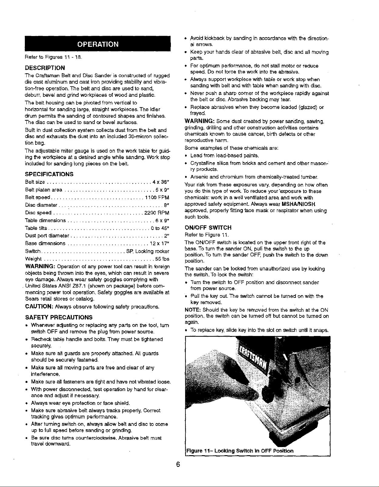
ON/OFF SWITCH
Refer to Figure 11.
The ON/OFF switch is located on the upperfront rightof the
base.To turn the sander ON, puff the switch to the up
position. To turn the sander OFF, push the switchto the down
position.
The sander can be locked from unauthorized use by locking
the switch. To lock the switch:
* Turn the switch to OFF position and disconnect sander
from power source.
• PuE{the key out,The switch cannot be turned on with the
key removed.
NOTE: Should the key be removed from the switchat the ON
position, the switch can be turned of_but cannot be turned on
again.
* To replace key,slide key into the slot on switch until it snaps.
11- Locking Switch in OFF Position
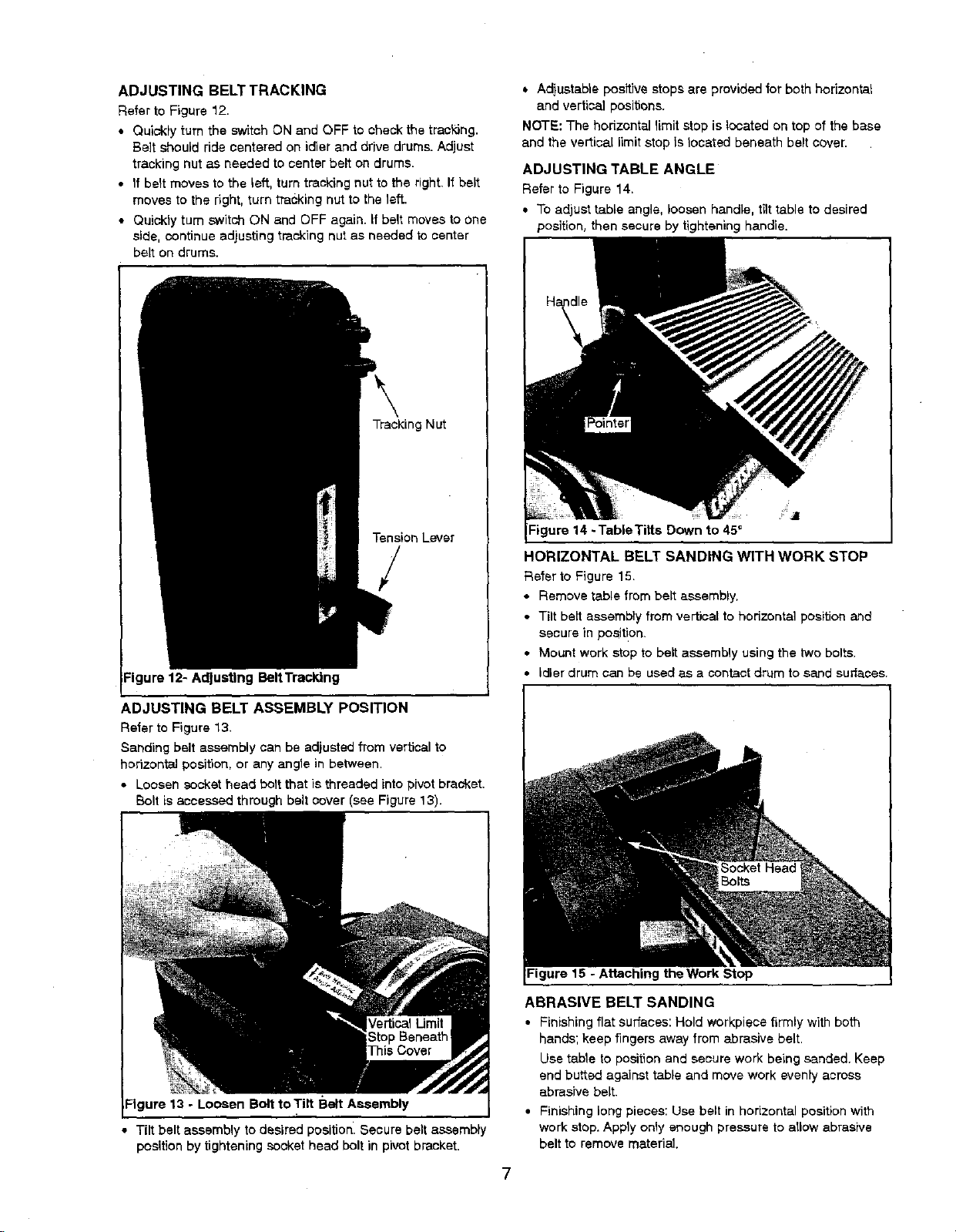
ADJUSTINGBELTTRACKING
RefertoFigure 12,
• Quickly turn the sWitch ON and OFF to check the traskJng.
Be]t should ride centered on idler and drive drums. Adjust
tracking nut as needed to center belt on drums.
• If belt moves to the left, turn tracking nut to the right, If belt
moves to the right, turn tracking nut to the left.
• Quickly turn switch ON and OFF again, if belt moves to one
side, continue adjusting tracking nut as needed to center
belt on drums.
Tracking Nut
• Adjustable positive stops are provided for both horizontal
and vertical positions.
NOTE: The horizontal limit stop is located on top of the base
and the vertical limit stop Is located beneath belt cover.
ADJUSTING TABLE ANGLE
Refer to Figure 14.
• To adjust table angle, loosen handle, tilt table to desired
position, then secure by tightening handle.
Tension Lever
/
Figure 12- Adjusting BeltTracldng
ADJUSTING BELT ASSEMBLY POSITION
Refer to Figure 13.
Sanding belt assembly can be adjusted from vertical to
horizontal position, or any angle in between.
• Loosen socket head bolt that is threaded into pivotbracket.
Bolt is accessed through belt cover (see Figure 13).
Figure 14 -TableTitts Down to 45_
HORIZONTAL BELT SANDING WITH WORK STOP
Refer to Figure 15.
• Remove table from belt assembly.
• Tilt beti assembly from vertical to horizontal positionand
secure in position.
• Mount work stop to belt assembly using the two bolts.
• idler drum can be used as a contactdrum to sand surfaces.
Figure 15 - Attaching the Work Stop
Figure 13 - Loosen Bolt to Tilt Belt Assembly
• Tilt belt assembly to desired position. Secure belt assembly
position by tightening socket head bolt in pivot bracket.
ABRASIVE BELT SANDING
• Finishing flat surfaces: Hold work,piece firmly with both
hands; keep fingers away from abrasive belt.
Use table to position and secure work being sanded. Keep
end butted against table and move work evenly across
abrasive belt.
• Finishing long pieces: Use belt in horizontal position with
work stop. Apply only enough pressure to allow abrasive
belt to remove material.
Use work stop to position and secure work being sanded.
Keep end butted against work stop and move work evenly
across abrasive belt, Use extra caution when finishing very
thin pieces.
• Finishing curved edges: Finish outside curves on flat por-
tion of abrasive bell Finish inside curves on idler drum por-
tion of abrasive belt.
• Finishing sod grain: It is more convenient to finish ends of
long workpiecss wild the abrasive belt in a vertical position.
Position table on belt side of sander. Move work evenly
across abrasive belt. For accuracy, use miter gauge. Table
may be tilted for beveled work.
ABRASIVE DISC SANDING
• Abrasive disc sanding is well suited for fitlishing small fiat
surfaces and convex edges.
• Move workpiece across down side (left) of abrasive disc.
Hold workplace firmly with both hands; keep fingers away
from abrasive disc.
• Abrasive disc moves fastest and removes more material at
outer edge.
• For accuracy, use miter gauge,
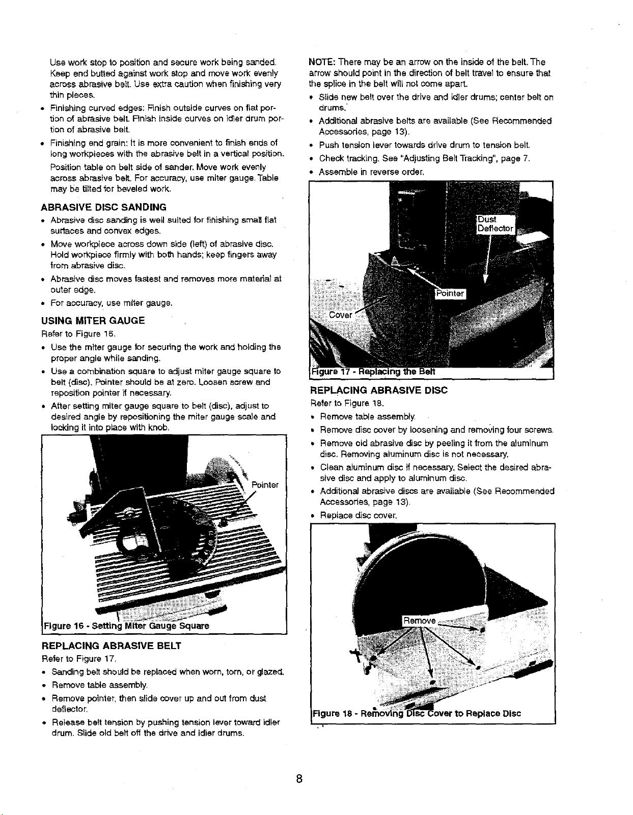
USING MITER GAUGE
Refer to Figure 16.
• Use the miter gauge for secudng the work and holding the
proper angle while sanding.
• Use a combination square to adjust miter gauge square to
belt (disc). Pointer should be at zero. Loosen screw and
reposition pointer if necessary.
• After setting miter gauge square to belt (disc), adjust to
desired angle by repositioning the miter gauge ssale and
locking it into place with knob.
Pointer
NOTE: There may be an arrow on the inside of the belt.The
arrow should point in the direction of belt travel to ensure that
the splice in the belt will not come apart.
• Slide new belt over the drive and idler drums; center belt on
drums.'
• Additional abrasive belts are available (See Recommended
Accessories, page 13).
• Push tension lever towards drive drum to tension belt.
• Check tracking. See "Adjusting Belt Tracking", page 7.
• Assemble in reverse order,
REPLACING ABRASIVE DISC
Refer to Figure 18.
• Remove table assembly.
• Remove disc cover by loosening and removing four screws.
• Remove old abrasive disc by peeling it from the aluminum
disc, Removing aluminum disc is not necessary.
• Clean aluminum disc if necessary. Select the desired abra-
sive disc and apply to aluminum disc.
• Additional abrasive discs are available (See Recommended
Accessories, page 13).
Replace disc cover.
Figure 16 - Setting Miter Gauge Square
REPLACING ABRASIVE BELT
Refer to Figure 17.
• Sanding belt should be replaced when worn, torn, or glazed.
• Remove table assembly.
• Remove pointer, then slide cover up and out from dust
deflecteL
• Release belt tension by pushing tension lever toward idler
drum. Slide old belt off the drive and idler drums.
Figure 18 -
 Loading...