

Craftsman 351215160, 351215080 Owner’s Manual

Operator's Manual g
4 X 8" and
6 x 12"
SANDING CENTERS
Model Nos.
351.215080
351.21 5160
CAUTION: Read and follow
all Safety Rules and Operating
Instructions before First Use
of this Product.
Sears, Roebuck and Co., Hoffman Estates, IL 60179 U.S.A.
www.sears.com/craftsrnan
20666.01 Draft (07/01{03)
az_n_r_x 9110/2003 I0:38 PAGE 3141 RightF&x
• Work area should be prepedy lighted.
• Proper electrical receptacle should be available for toot
Warranty ......................................... 2
Safety Rules ...................................... 2
Unpacking ....................................... 3
Assembly ...................................... 3-6
Installation ...................................... 6-7
Operation ..................................... 8-11
Maintenance .................................... 12
Troubleshooting .................................. 13
parts Illustrattan and List ........................ 14-25
Espa5ol ...................................... 26-39
FULL ONEYEAR _RRANTY
If _is product fails du6 to a defect in material or workmanship
within one year from the date of purchase, Sears will at its
option repair or replace itfree of charge. Contact your nearest
Sears Service Center (1-800-4.MY-HOME) to arrange for prod-
uct repair, or mtum this product to place of purchase for
replacement
If this product is used for commercial or rental purposes, this
warranty will apply for 90 days from the data of purchase.
This warranty appitas onlywillie this product is used in the
United States
This warranty gives you spastic legal rights, and you may also
have other rights which very from state to state.
Sears, Roebuck and Co., Dept, 817WA, Hoffman Estates,
IL 60179
WARNING: For your own safety, mad all of the Insfructlons
and precautions before operating tool,
CAUTION: Always follow proper operating procedures as
defined in this n'_nual even if you are familiar with use of this
or similar tools. Remember that being careless for even a
fraction of a second can result In severe pemonal Injury.
BE PREPARED FOR JOB
• Wear proper apparel, Do not wear loose clothing, gloves,
neckties, dnga, bracelets or other jewelry which may get
caught in moving parts of machine.
• Wear protective hair covering to contain long hair.
• Wear safety shoes with non-slip soles.
• Wear safety glasses complying with United States ANSI
Z87.1. Everyday glasses have only impact resistant lenses.
They are NOT safety glasses.
• Wear face mask or dust mask if operation is dusty
• Be alert and think clearly. Never operate power tools when
tired, intoxicated or when taking medica_orls that cause
drowsiness.
PREPARE WORK AREA FOR JOB
• Keep work area ctean. Cluttared work areas invite accidents
• Oo not use power tools in dangerous environments. Do not
use power tools in damp or wet locations. Do not expose
power tools to rain.
Three prong plug should be plugged direcSy into properly
grounded, three-prong receptacte.
• Extsosien cords snduld have a grounding prong and the thr,..=e
wires of the extension cord should be of the correct g_uge.
• Keep visitors at a safe distance from work area.
• Keep children out of workplace. Make workshop childproof.
Use padlocks, master switches or remove switch keys to
prevent any unintant{ocal use of power too{s.
TOOL SHOULD BE MAINTAINED
• Always unplug tool prior to Inspection.
• Consult manual for sbeciflc maintaining and adjusting
procedures.
• Keep tool lubricated end clean for safest operation,
• Remove adjusting tools. Form habit of checking to see that
adjusting tcx_tsare removed before switching machine on.
• Keep all paris in w_rking order. Check ta determine that the
guard or other parts will operate properly and perform their
intended function.
• Check for damaged parts. Check for alignment of moving
parts, binding, breakage, mounting and any other condition
that may affect a _ol's operation.
• A guard or other part that is damaged should be properly
repaired or replaced. Do not perform makesh_ repairs
(Use parts list provided to order replacement parts.)
KNOW HOWTO USE TOOL
• Use nght tool for job. Do not force tool or attachment to do
a job for which it was not designed.
• Disconnect tool when changing belt or abrasive disc.
• Avoid accJdantal start-up Make sure that the tool is in the
"OFF" posilJonbefore plugging in.
• Do not forca tool. It will work most efficiently at the rate for
which it was designed.
• Keep bends away from moving parts and sanding surfaces
• Never leave tool running unattended. Turn the power off
and do not leave tool until Itcomes to a complete stop
• Do not overreach. Keep proper footing and balance.
• Never stand on tool. Serious injury could occur If tool is
tipped or ff beltordiscare unlntentioneltyconta_ed.
• Know your tool. Learn the t_::#s ope,,'ati_n, app_icat)ot_ and
specific limitations,
• Use Recommended Accessories (refer to pages 19 and
25). Use of improper accessories may cause risk of injury
to persons.
• Handle the workplace correctly. Protect hands from possi-
ble injury.
• Turn machine otf if itjams. Beltjams when it digs too deeply
intoworkpiece. (Motor force keeps it stuck inthe work,)
• Support workplace with miter gauge, belt platen or work
table.
• Maintain 'As_ maximum ciearanse hetweerl table and sand-.
ing belt or disc.
CAUTION: Think safety! Safety is a combination of operator
common sense and alertness at air times when tool is being
used.
WARNING'. Do not attempt to operate tool until it is com-
pletely essembisd according to the instructions.
© Sears, Roebuckand Co. 2
_i_htFax 9/10/2003 10:38 PAGE 4/41 RightFax
MOUNT SANDING CENTER
Refer to Figures 2 and 3.
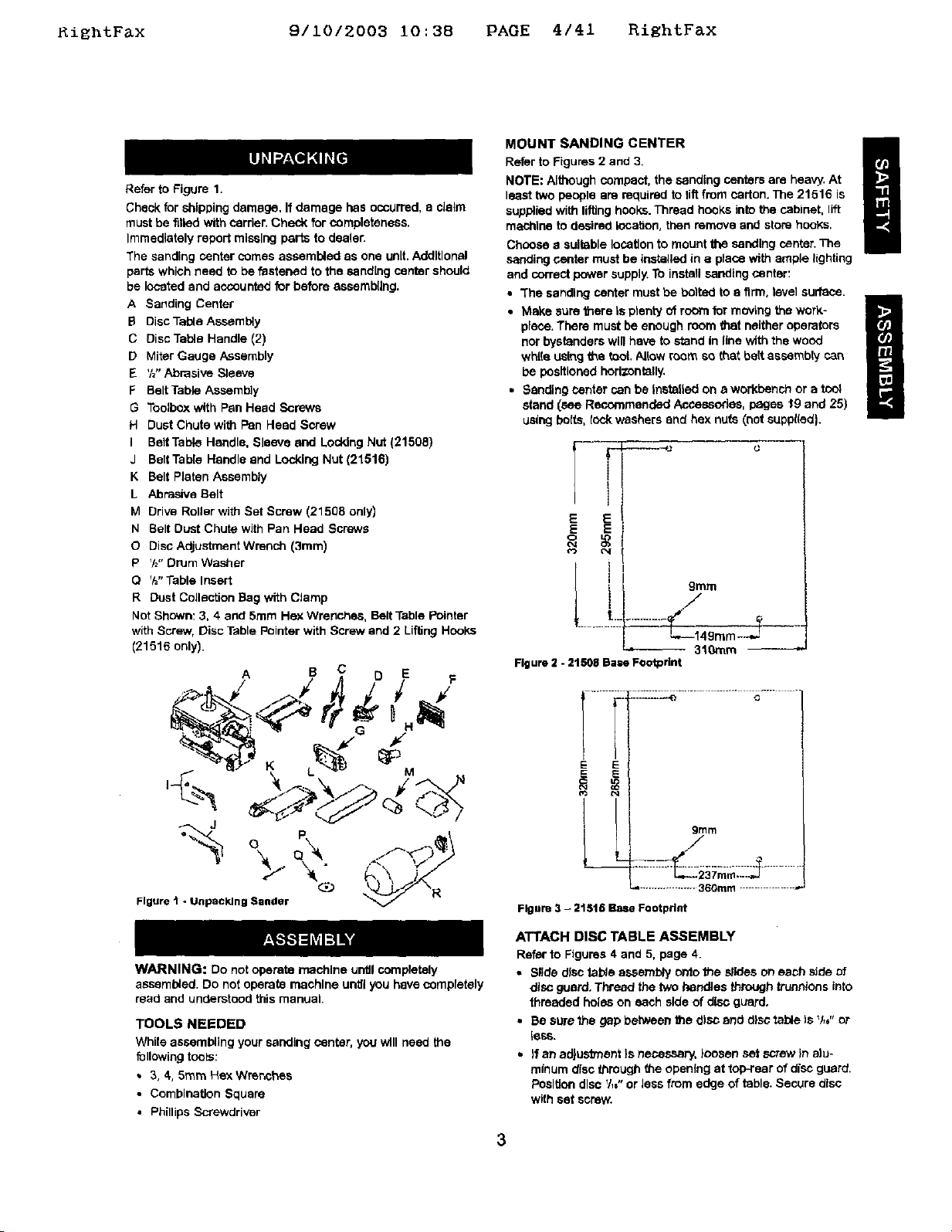
Refer to Figure 1.
Check for shipping damage, If damage has occurred, a claim
must be filled with carrier, Check for completeness.
Immediately repeit missing pal"is to dcoter.
The sanding center comes assembled as one unit.Additional
parts which need to be fastened to the sand[rig center should
be located and accounted for before assembling.
A Sanding Center
B Disc Table Assembly
C Disc Table Handle (2)
D Miter Gauge Assembly
E %" Abrasive Sleeve
F Belt Table Assembly
G Toolbox with Pan Head Screws
H Dust Chute with Pan Head Screw
I BeltTable Handle, Sleeve and Locking Nut (21508)
J Belt Table Handle and Locking Nut (21516)
K Belt Platen Assembly
L Abrasive Belt
M Drive Roller with Set Screw (21508 only)
N Belt Dust Chute with Pan Head Screws
O Disc Adjustment Wrench (3ram)
P V="Drum Washer
O %'Table Insert
R Dust Collection Bag with Clamp
Not Shown: 3, 4 and 5ram Hex Wrenches, Belt Table Pointer
with Screw, Disc Table Pointer with Screw and 2 Lifting Hooks
(21516 only).
NOTE: Although compact, the sanding centers are heavy, At
least two people are required to riftfrom carton. The 21516 is
supplied with lifting hooks. Thread hooks into the cabinet, lift
machine to desired lecaUon, then remove and store hooks,
Choose a suitable location to mount the sanding center. The
sanding center must be installed in a place with ample lighting
and correct power supply. To install sanding center:
• "The sanding center must be bolted to a firm, level surface.
place, There must be enough room that neither operators
nor bystanders will have to stand In line with the wood
white L_sthg the tool. Allow room so that belt assembly can
be positioned horizontally.
• Make sure there Is plenty of room for moving the work-
• Sanding center can be Installed on a workbench or a tool
stand _sse Recommended Accesoodes, pages t9 and 25)
using bolts, t_:t_ washers end hex nuts (not suppl(ed).
E E
E E
O4
9tara
L i, ./
L._149m m_...J=
Figure 2 - 21508 Base Footprint
-- 310mm
A S C DE
.::IL-L-e............ .,j......
i
%o
Figure t - Unpacking Bander @ __\R
WARNING: Do not operate machine until coreptetely
assembled. Do not operate machine until you have completely
read and understood this manual.
TOOLS NEEDED
While assembling your sanding center, you will need the
following tools:
• 3, 4,5ram Hex Wrenches
• Combination Square
• Phillips Screwdriver
I ._,....i
E E
grllm
/
./
...................360ram .................
Figure 3 - 21516 Base Footprint
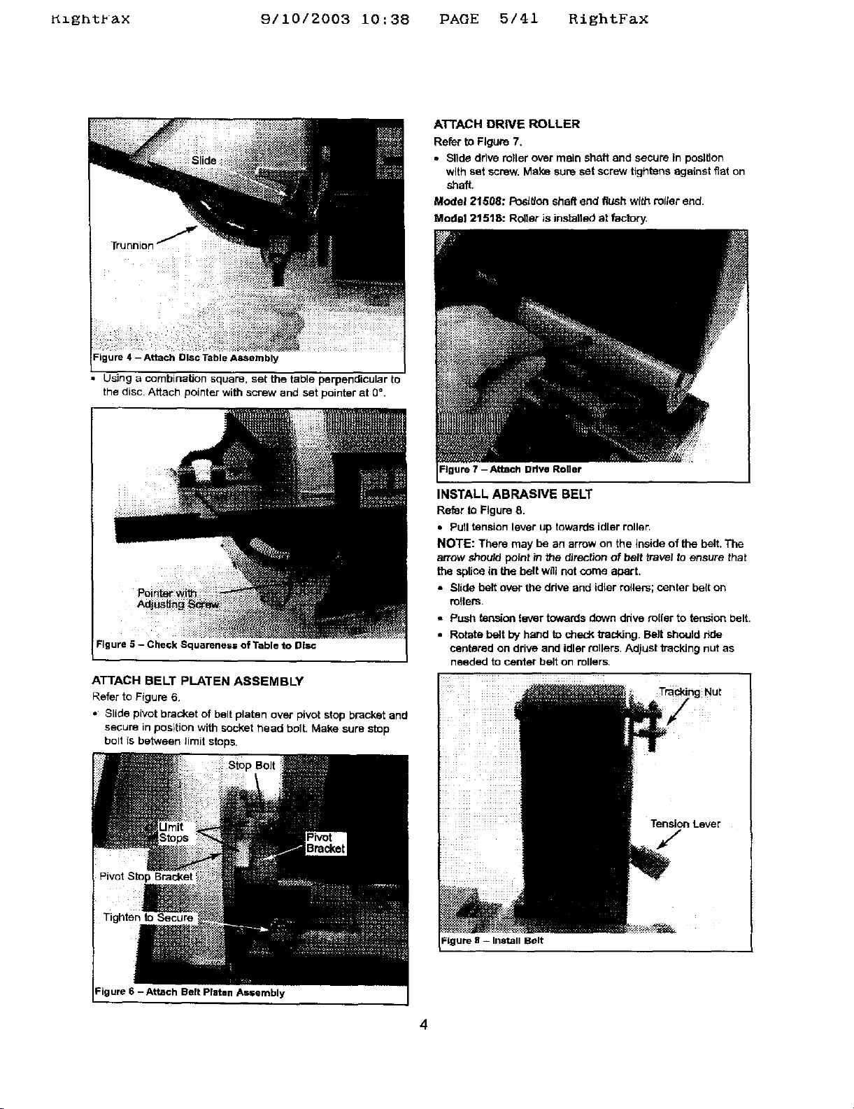
ATTACH DISC TABLE ASSEMBLY
Refer to Figures 4 and 5, page 4.
• Silde disc table assembly outo the slides on each side of
disc guard. Thread the two handles through truenlons into
threaded holes on each side of disc guard.
• Be sure the gap between the disc and disc table Is V,," or
tess.
• )f an adjustment }s necessary, loosen set screw in alu-
minum disc througt_ the opening at top-rear of disc guard.
Posltlen disc V,," or less from edge of table. Secure disc
with set screw.
3
Rlghtr&X 9110/2003 10:38 PAGE 5141 RightFaX
A'FFACH DRIVE ROLLER
Refer to Figure 7,
• Slide drive miler over main shaft and secure in position
with set sorew. Make sure set screw tightens against fiat on
shaft.
Model 21508: Posltlon shaft end flush with rotter end.
Modal 21518: Roller is installed at factory,
Trunnion
Figure 4 - Attach Disc i-able ASSembly
• Using a combination square, set the table perpendicular to
the disc. Attach pointer with screw and set pointer at 0 °.
Figure 5 - Check Squarenes= of Table to Disc
I
ATTACH BELT PLATEN ASSEMBLY
Refer to Figure 6,
• Slide pivot bracket of belt platen over pivot stop bracket and
secure in position with socket head bolt. Make sure stop
bo!t is between limit stops.
Figure 7 - Attach Drive Roller
INSTALL ABRASIVE BELT
Refer to Figure 8.
• Pull tension lever up towards idler roller.
NOTE: There may be an arrow on the inside of the belt. The
arrow should point tn the _rection of belt travel to ensure that
the splice in the belt will not come apart.
• Slide belt over the ddve and idler milers; center belt on
milers.
• Push tension lever towards down drive miler to tension belt.
• Rotate belt by hand to sheck tracking. Belt should r_de
centered on drive and idler rollers. Adjust kacking nut as
needed to center belt on rollers
To gNut
Tension Lever
Pivot Stop Bracket
Tighten to Secure
Figure 6 - Attach Belt Platen As=embly
Belt
4
KzgntPax 9/10/2003 i0:38 PAGE 6/41 RightFax
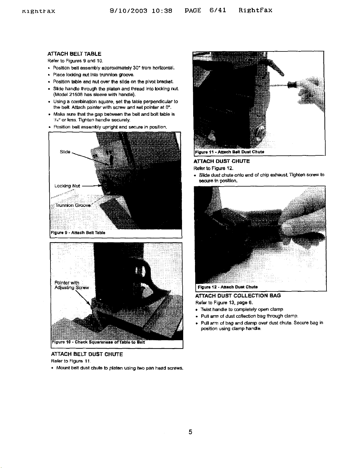
ATTACH BELT TABLE
Refer to Figures 9 and 10.
• Position belt assembly approximately 30" from horizontal,
• Place locking nut Into trunnion groove.
• Position table and nut over the slide on the pivot bracket.
• Slide handle _mugh the platen and thread into locking nut.
(Model 21508 has sleeve with handle).
• Using a combination square, set the table perpendicular to
the bell Attach pointer with screw and set pointer at 0".
• Make sure thai the gap between the belt and bolt table is
'/_," or less Tighten handle securely.
• Position belt assembly upright and secure in position.
Igure 11 - Attach Belt Dust Chute
ATTACH DUST CHUTE
Refer to Ffguse 12.
• Slide dust chute onto end of chip exhaust. T'_jhtan so'-ew to
secure In _tt[on.
Figure 9 - Attach Belt Table
- Check Squareness o :Table to Belt
ATTACH BELT DUST CHUTE
Refer to Figure 11.
• Mount belt dust chute to p/aten using two pan head screws.
Figure 12 - Attach Dust Chute
ATTACH DUST COLLECTION BAG
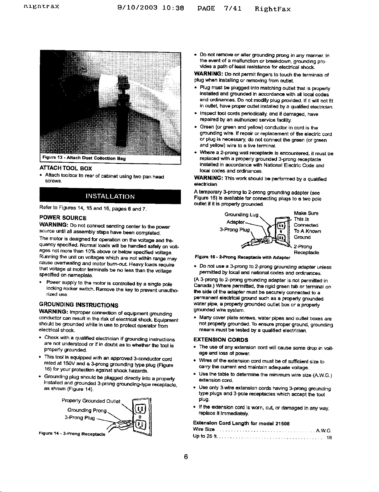
Refer to Figure 13, page 6.
• Twist handle to completely open clamp
• Pull arm of dust collection bag through clamp.
• Pull arm of bag and clamp over dust chute. Secure bag in
position using clamp handle.
5
_l_n%r_x 9/1012003 10:38 PAGE 7/41 RightFax
• 0o not remove or alter grounding prong in any manner. In
the event of a maifunction or breakdown, grounding pro-
vides a path of least resistance for electhcal shock.
WARNING: Do not permit _ngers to tov_h the terminals of
plug when installing or removing from outlet.
• Plug must be plugged into matching outlet that is properly
installed and grounded in accordance with all local codas
and ordinances. Do not modify plug provided. If Itwill not fit
in outlet, have proper outlet installed by a qualified electhcian
• Inspect _ol cords pehodicsily, and if damaged, have
repaired by an authedzed service facility.
• Green _orgreen and yetlow)conductorincordis the
gmueding wire. If repair or replacement of the electric cord
or plug is necessary, do not connect _ green (or green
and yellow) wire to a tire terminal
• Where a 2-prong wail receptac_ is encountered, it must be
Figure 13 -Attach Dust Collection Bag
ATTACH TOOL BOX
• Attach toolbox to rear of cabinet using two pan heed
screws.
Refer to Figures 14, 15 and 16, pages 6 and 7.
POWER SOURCE
WARNING: De not connect sanding center to the power
source _ntif a_ assembly steps have been comp|eted.
The motor is designed for operation on the voltage and fre-
quency specified. Normal loads will be handled sately on volt-
ages not more than 10% above or below specified voltage.
Running the unit on voltages which are not within range may
cause overheating and motor bum-ouL Heavy toads require
that voltage at motor terminals be no less than the voltage
specified on nameplate.
• Power supply to the motor is controlled by a single pole
locking rocker switch. Remove the key to prevent unautho-
rized use
GROUNDING INSTRUCTIONS
WARNING: Improper connection of equipment grounding
conductor can result in the dsk of electdcal shock_Equipment
should be grounded while In use to protect operator from
electrical shock.
• Check With a quatif_ etectn_an ff grounding ins_uctions
are not understood or if in doubt as to whether the tcol is
properly grounded.
• This tool is equipped with an approved 3-coeductor cord
rated at 15or and e 3-preng grounding type plug (Figure
16) for your protecl_n against shock hazards.
• Grounding plug should be plugged directly into a properly
installed and grounded 3-prong grounding-type receptacle,
as shown (Figure 14}.
Properly Grounded Outlet _----_
Groundthg Prong _"J_) II
3-Prong Plug -___
Figure 14 - 3-Prong Receptacle
replaced with a properly grounded 3-preng receptacle
installed in accordance with National Electric Code and
local codes and ordinances.
WARNING: This work should be performed by a qualified
electttdan
A temporary 3-prong to 2-preng grounding adapter (see
Figure 15) Is evetleb_e for cor,r,ec'_',gptugs to e two pole
outlet if it is propedy grounded.
Grounding Lug _ _ Make Sure
Ariapter--......._.'"_, .._ Connected
3-ProngPtug\ \_ I'_--"II ToAK_,,o
Figure 15 - 2-Prong Re©eptacle with Adapter
• Do not use a 3-prong to 2-prong grounding adapter unless
permitted by local and nationsi codes and ordinances.
(A 3-prong to 2-prong grounding adapter is not permitted in
Canada.) Where permitted, the rigid green tab or terminal on
the side of the adapter must be securely connected to a
permanent alecbical ground such as a prepedy grounded
water pipe, e property grounded outlet boy.or a properly
grounded wire system.
• Many cover plate screws, watar pipes and outlet boxes are
not properly grounded. To ensure proper ground, grounding
means must be tested by a qualified etectdcian.
EXTENSION CORDS
• The use of any extension cord will cause some drop in volt-
age and loss of power.
= Wires of the extension cord must be of sufficient size to
carry the current and maintain adequate v_tage.
• Use the table to determine the minimum wire size (A.W.G.I
extension cord.
• Use only 3-wtre extension cords having 3-prong grounding
type ptugs and 3-pole te_des which acr_pt the toot
plug.
• Ifthe extension cord Is worn, cut, or damaged In any way,
replace it Immediately,
Extension Cord Lengt_ for model 21508
Wire Size .................................. AWG
Up to 25 ft ....................................... 18
This Is
round
_ 2-Prong
Receptacle

Ignt ax 9/10/2003 10:38 PAGE 8/41 RiEhtFax
NOTE: Using extension cords over 25 ft. long is not
recommended.
Extension Cord Length for model 21516
Wire Size ................................... A.W.G.
Upto25ff ....................................... 14
NOTE: Using extension cords over 25 ft. long is not
recommended
MOTOR
The sanding centers are assembled with motor and wiring
installed as an integral part of the tool. The electrical wiring
schematic is shown in Figure 16.
21508 MOTOR SPECIFICATIONS:
Horsepower (Maxlmurn Developed) .................... 1
Voltage ........................................ 120
Amperes ....................................... T,5
Hertz .......................................... 60
Phase ..................................... Single
Rotation (viewed from left side) ................ Cl_-kwise
21516 MOTOR SPECIFICATIONS:
Horsepower (Maximum Developed} .................... 3
Voltage ........................................ 120
Amperes ........................................ 13
Hertz .......................................... 60
phase ....................................... Single
Rotation (viewed @ore left side) ................ Clockwise
ELECTRICAL CONNECTIONS
WARNING: All electrical connec_ns must be performed by
a qualified electrician. Make sure tool is off and disconnected
from power source while motor is mounted, connected, recon-
nected or anytime wiring is inspected.
Motor and wires are installed as shown in wiring diagram
(See Figure 16). Motor is assembled with approved, 3-con-
ductor cord to be used at 120 volts.
The power lines are inserted directly onto the switch. The
green ground line must remain securely fastened to the frame
to properly protect against electrical shock. The power supply
to the motor is controlled by a single pole idoldng rocker switch.
• Remove the key to prevent unauthorized use.
Sw_tch
oS_lac_L__-----3___ ........
Li eco, ,........ ..................
Figure 16 - Wlrteg Diagram
DESCRIPTION
The Craftsman Sanding Centers are constructed of rugged die
cast aluminum and cast iron providing stability and vibration-
free operation. The sanding centers are used to sand, deburr,
bevel and grind large workpieces of wood, plastic and metal.
Mechanical variable speed feature allows precise control of
matedal removal rate.
Motor
Built-in dust colle_on system collects dust from the belt, disc
and spindle. Dust is exhausted into one included dust collection
bag. The belt housing can be pivoted from vertical to horizontal
for sanding large, straight workpieces. The belt assembly
includesa t_16ng,cast iron table with miter gauge and dust
collectionchute. The disc can be used to sand or bevel
SUlfates with the use of 0 to 45" scaled aluminum table. The
disc assambly includes a tilting table with miter gauge slot and
dust coltactionchute. The osdtiaiJng spindle pern#rtsthe sand-
ing of contoured shapes. The oscillating motion of the spindle
prevents I_'nlng of the workptace end Increases abrasive
sleeve life. The a_ustab_e miter gauge can be used on both the
belt and disc tables for guiding the workplece at a desired
angle while sanding.
SPECIFICATIONS
MODEL 21508
Belt size .................................... 4 x 36"
Belt platen area ............................. 4_[,x 1 ! _
Belt table dimensions ........................... 5 x 8"
Belt table tilts................................ 0 to 45°
Belt speed ............................ 350-2300 FPM
Disc diameter .................................... 8"
Disc table direanslens ......................... 6 x 11"
Disc tsbte firs ............................... O to 4Y
Disc speed ............................ 550-3500 RPM
SpindJe size ..................................... _1_"
Spindle drum capacity ............................. 1"
Spindle speed ........................ 275 - 1000 RPM
Spindle oscitialion rate ...................... 57/mintae
Spindle sf_oke ................................... _"
Spindle table size ............................. 8 x 12"
Overall dimensions ..................... 30 x 22 x 18Vz"
Switch ............................. SP, LoCking rocker
Weight ..................................... 135 ths
MODEL 2151S
Belt size .................................... 6 x 48"
Belt platen area ............................. 7 × 1B_t,"
Belt table dimensions .......................... 6 x 10"
Belt table tilts................................ 0 to 45°
Belt speed ............................ 505-2800 FPM
Disc diameter ................................... 12"
Disc I_ble dimensions ......................... 7 x 15"
Disc table lilts ............................... 0 to 45 °
Disc Speed ............................ 750-3600 RPM
Spindle size ..................................... V_"
Spindle drum capacity ............................. 1"
Spindle speed ........................ 375 - 1800 RPM
Spindle oscillation rate ....................... 57/minute
Spindle stroke ................................... _f,"
Sp_ndis table size ............................ 8% x 12"
Overall dimensions ................... 33'1zx 29'h x 20'/,,"
Switch ............................. SR Locking rocker
Weight ..................................... 200 Ibs
7
_1_n_rax 9/10/2003 10:38 PAGE 9/41 RightFax
WARNING: Operation of any power tool can result in foreign
objects being thrown into the eyes, which can result in severe
eye damage. Always wear safety goggles complying with
United States ANSi Z87.1 (sl_own on package} before com-
mencing power tool operation. Safety goggles are available at
Sears retail stores or catalog.
CAUTION: Always observe following safety precautions.
SAFETY PRECAUTIONS
• Whenever adjusting or replacing any parts on the tool, turn
switch OFF and remove the plug from power seams
• Recheck table handles. They must be tightened securely.
• Make sure ell guards are properly attached, All guards
should be securely fastened.
• Make sure all moving parts are free and clear of any
interference.
• Make sure all fasteners are tight and have not vibrated
loose.
• With power disconnected, test operation byhand for clear°
ance and adjust If necessary.
° Always wear eye protection or face shield.
° Make sure abrasive belt always tracks properly. Correct
tracking gives optimum performance,
• After turning switch on, always allow belt, disc and spindle
to come up to full speed before sanding or grinding.
• Be sure motor runs clockwise on disc side. Abrasive belt
must travel down.
• Avoid kickback by sanding in accordance with the direction-
sl a rrow_
• Feed workplace against rotation of the sanding drum.
• Keep your hands clear of abrasive belt, disc end spindle.
• Make sure sanding drum Is properly secured on the spindle
before operating.
° Always keep the spindle table Insert In place. Use the
correct size insert for each sanding sleeve.
* Clear debris from belt, disc and spindle tables before
sanding any workplace.
• For optimum performance, do not stall motor or reduce
speed. Do not force the work into the abrasive.
• Support workplace with belt table when sanding with belt,
with disc table when sanding with disc, with spindle table
when sanding with spindle.
. Never push a sharp comer of the work.piece rapidly against
the belt, disc or spindle. Abrasive backing may tear.
• Replace abrasives when they become loaded (glazed) or
frayed
• When grinding metal, move workpisce across abrasive to
prevent heat built up
• Never attempt wet sanding. If the workpieoa becomes too
hot to handle, cool it in water,
OPERATING CONTROLS
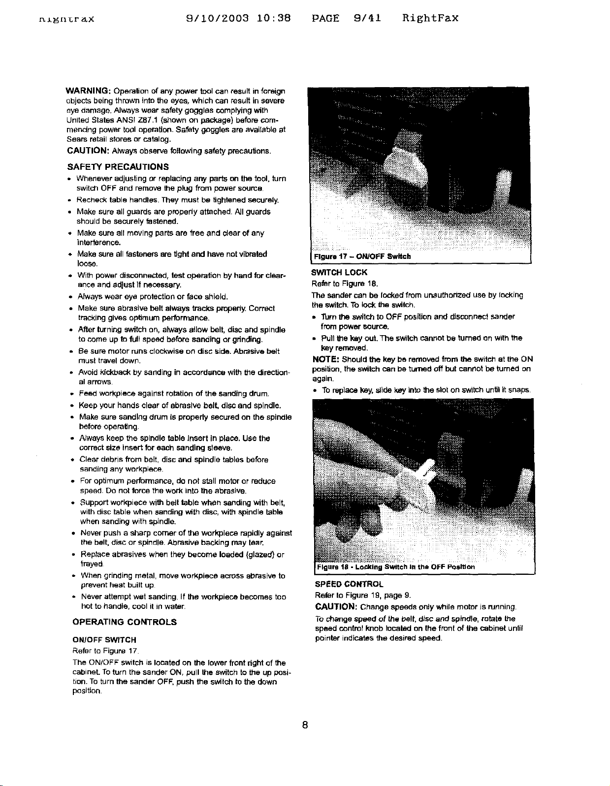
ON/OFF SWITCH
Refer to Figure 17.
The ON/OFF sw_tch is located on the lower front right of the
cabinet. To turn the sander ON, pull the switch to the up posi-
tion. To turn the sander OFF, push the switch to the down
position.
Figure t7 - ON/OFF Switch
SWITCH LOCK
Refer to Figure 18.
The sander can be locked from unauthorized use by tacking
the switch. To lock the switch.
• Turn the switch to OFF position and disconnect sander
from power source.
• Pull the key out. The switch cannot be turned on with the
key removed.
NOTE: Should the key be removed from the switch at the ON
position, the switch can be turned off but cannot be turned on
again.
• To replace key, slide key into the slot on _th.h untilit snaps
Figure 18 - Lo_klng Switch I. the OFF Position
SPEED CONTROL
Refer to Figure 19, page 9.
CAUTION: Change speeds only while motor Jsrunning.
To change speed of the belt, disc and spindle, rotate the
speed control knob located on the front of the cabinet until
pointer indicates the desired speed.
8
_ight_&x 9/10/2003 i0:38 PAGE 10/41 RightFax
Figure 19 -Speed Control
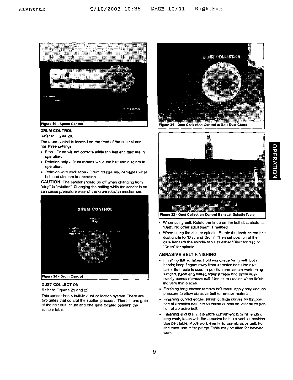
DRUM CONTROL
Refer to Figure 20
The drum control is located on the front of the cabinet and
has three settings:
. Stop - Drum will not operate while the belt and disc are in
operation.
• Rotation only - Drum rotates while the belt end disc ere In
operation.
• Rotation with oscillation - Drum rotates and oscillates while
belt and disc are in operation,
CAUTION: The sander should be off when changing from
"stop" to "rotation". Changing the setting while the sander is on
can cause premature wear of the drum rotation mechanism.
:lgure 20 - Drum Control
DUST COLLECTION
Refer to Figures 21 and 22.
This sander has a built-in dust collection system. Them are
two gates that control the suction pressure, There Is one gate
at the belt dusl chute and one gate located beneath the
spindle table.
=lgura21 - Bust Collection Control at Belt Dust Chute
Figure 22 - Duct Collection Control Beneath Spindle Table
• When using belt: Rotate the knob on the belt dust chute to
"Belt. No other adjustment is needed.
• When using the disc or spindle: Rotate the knob on the belt
dust chute to "Disc and Drum" Then set position of the
gate beneath the spindle table to either =Disc_ for disc or
"Drum" for spindle.
ABRASIVE BELT FINISHING
• Finishing flat surfaces: Hold workplace firmly with both
hands; keep fingers away from abrasive bell Use belt
table. Belt table is used to position and secure work being
sanded, Keep end butted against table and move work
evenlyacross abrasive belt. Use extra cau_on when finish-
ing very thin pieces.
• Finishing long plies: remove bait tebte. Apply only enough
pressure to allow abrasive belt to remove material.
• Finishing curved edges: Finish outside curves on fiat por-
tion of abrasive belt. Finish inside curves on idler d_um por-
tion of abrasive belt.
Finishing end grain: it is more convenient to finish ends of
long workpieces with the abrasive belt in a vertical position.
Use belt table. Move work evenly across abrasive belt. For
accuracy, use miter gauge. Table may be _lted for bevelect
work.
9
RightFax 9/10/2003 i0:38 PAGE ii/41 RightFax
ADJUSTING BELT TABLE
• TOadjust belt table angle, loosen bendta.
• Tilt belt table to desired position. Adjust for 'h6" maximum
clearance between the belt end the table. Secure by tJghto
ening handle.
ADJUSTING BELT ASSEMBLY POSITION
WARNING: Disconnectsanderfrom powersource,
• Loosensockethead boltthat [sthreaded Intopivotbracket.
• Tiltbelt assemblytodesiredposition(fromhodzontelto
vertical),Secure beltassemblypositionbytighteningsocket
head bolt In pivotbracket.
HORIZONTAL BELT SANDING
CAUTION: When the sandtagcenter Is mounted ona work-
bench, make sure the dust collection bag Is clear of the belt
assembly.
Refer to Figure 23.
• The belt platen can be tilted from a vertical to a horizontal
po.Sltlon.
• Remove the belt table by removing the handle arid locking
nuL Loosen the socket head bolt in the pivot bracket;,tilt the
belt platen assembly to the hodzental position and tighten
the socket head bolt to secure posiUoo.
• Idler roller can be used as a contact drum to sand surfaces.
Socket Head Belt
the Belt Aasembly
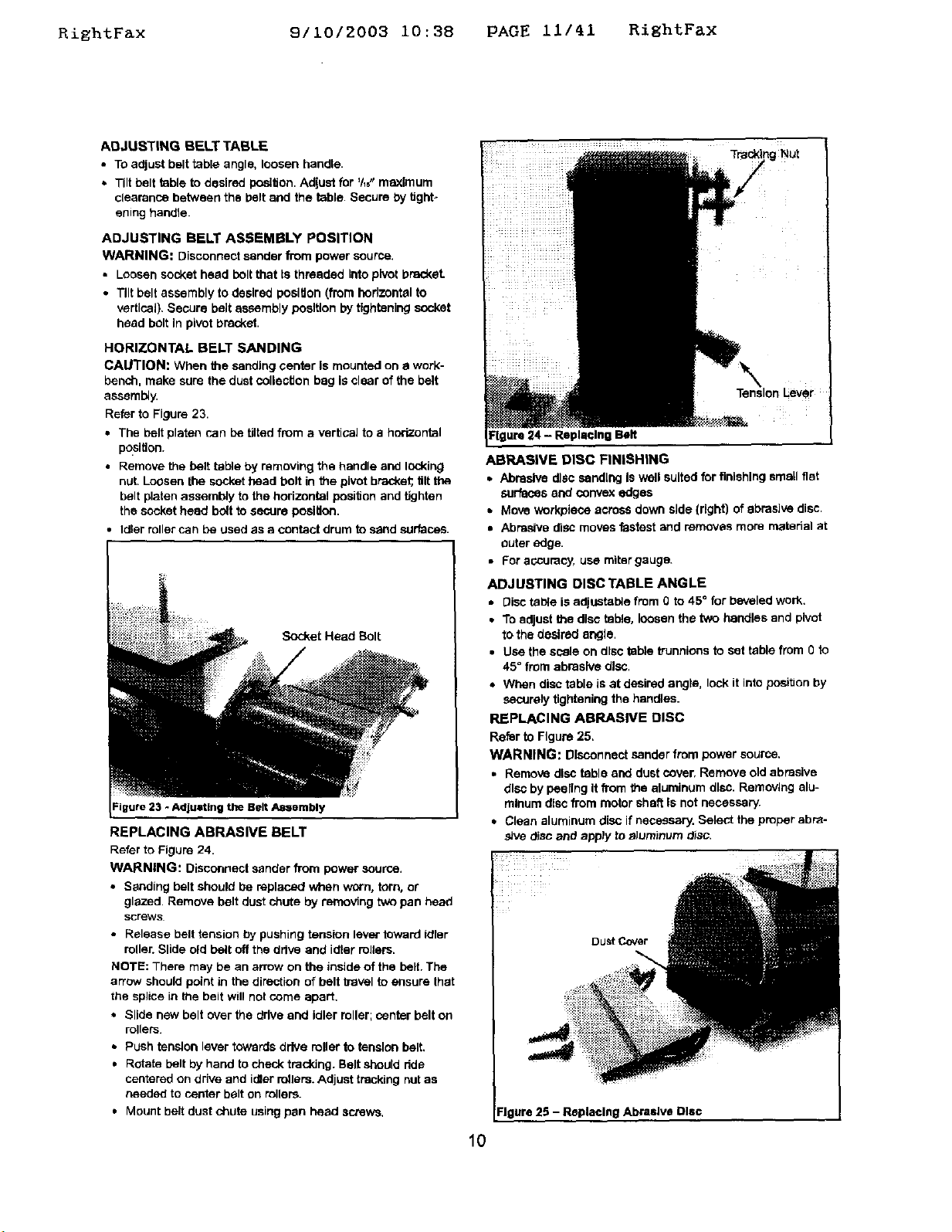
REPLACING ABRASIVE BELT
Refer te Figure 24.
WARNING: Disconnect sander from power source.
• Sanding belt should be replaced when worn, torn, or
glazed. Remove belt dust chute by removing two pan head
screws
• Release belt tension by pushing tension lever toward idler
roller. Slide old belt off the ddve and idler rollers.
NOTE: There may be an arrow on the inside of the belt, The
arrow should point in the direction of belt b-avel to assure that
the splice in the belt will not come apart.
• Slide new belt over the drive and idler roller; center belt on
rollers.
• Push tension lever towards drive roller to tension belt,
• Rotate belt by hand to check traddng. Belt should dde
centered on drive and idler rollers. Adjust tracldng nut as
needed to center belt on rollers.
• Mount belt dust chute using pan head screws.
ure 24 - Replacing Belt
ABRASIVE DISC FINISHING
• Abrasive disc eand[ng Is well suited for finishing smell fiat
surfaces end convex edges
• Move workpiece across down side {right) of abrasive disc.
• Abrasive disc moves fastest and removes more material at
outer edge.
• For accuracy, uce miter gauge.
ADJUSTING DISC TABLE ANGLE
• Disc table is adiustab_e from 0 to 45 ° for beveled work,
• To adjust the disc table, loosen the two handles and pivot
to the desired angle.
• Use the scale on disc table trunnions to set table from Oio
45° from abrasive disc.
• When disc table is at desired angle, lock it into position by
securely tightening the handles.
REPLACING ABRASIVE DISC
Refer to Figure 25,
WARNING: Disconnect sander from power source,
• Remove disc table end dust cover, Remove old abrasive
dlso by peeling It from the aluminum disc. Removing alu-
minute disc from motor shaft Is not necessary'.
• Clean aluminum disc ifnecessary. Select the proper abre-
she disc and apply to z_]uminumdisc.
DuSt Cover
Figure 25 - Replacing Abrasive Disc
Tre_ng NUt
10
RiEhtFax 9/10/2003 10:38 PAGE 12/41 RightFax
• Additional abrasive discs are available (See Recommended
Accessories, pages 19 and 25).
• Replace dust cover and disc table.
ABRASIVE DRUM FINISHING
WARNING: Position the belt assembly to the horizontal
posiUon before using the drum, If the belt is in the vertical
position, it may be unintentionally contacted causing injury,
• Abrasive drum sanding is well suited for finishing small fiat
surfaces and small contoured work,pieces.
• Support worl<piece on the table. Hold workplece with both
hands and keep finger away from drum,
• Always sand against the rotation of the sanding drum.
• Using the oscillation feature will help reduce scoring the
weft<piece and protong life of the abrasive sleeve.
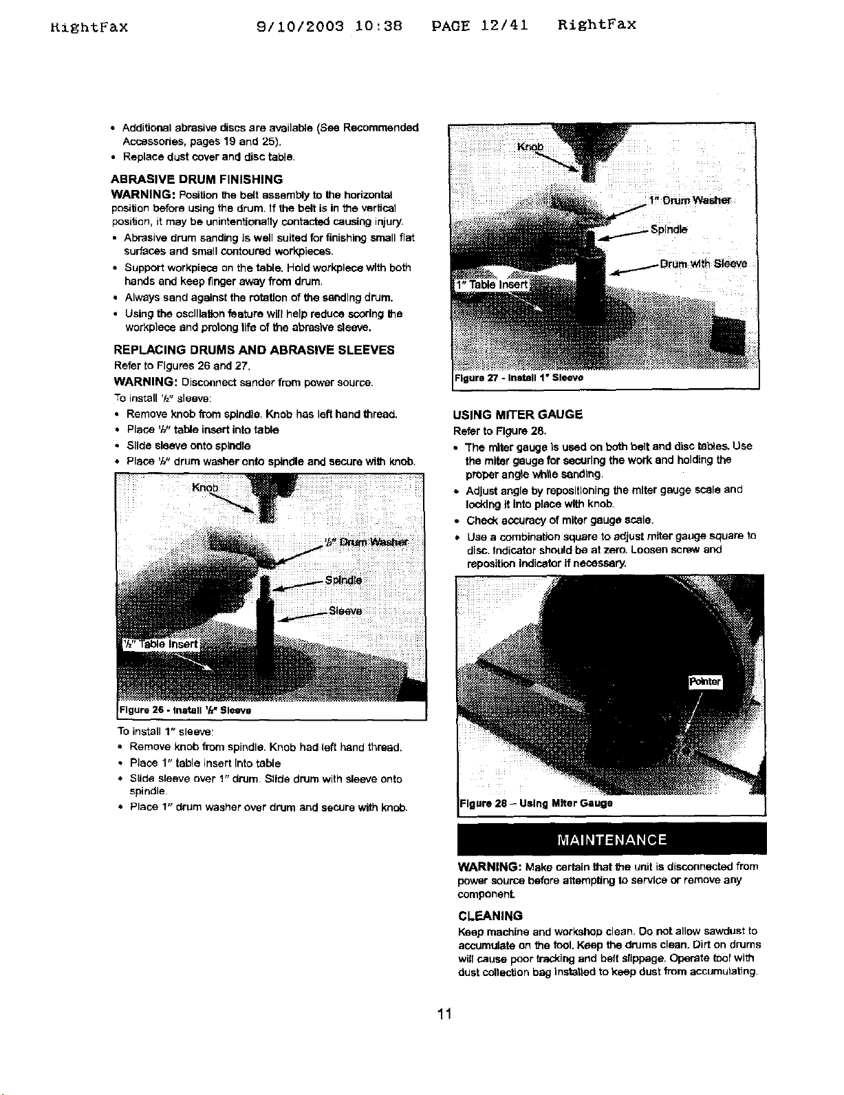
REPLACING DRUMS AND ABRASIVE SLEEVES
Refer to Figures 26 and 27.
WARNING: Disconnect sander from power source,
To install '/="sleeve:
• Remove knob from spindle, Knob has left hand thread,
• Place 'M"table insert into table
• Slide sleeve onto spindle
• Place 'W' drum washer ont_ spindle and secure with knob.
Figure 27 - Install 1" Sleeve
USING MITER GAUGE
Referto Figure28.
• "Themiter gauge Is used onboth belt and disctables.Use
the miter gaugeforsecuringthework and holdingthe
properangle whtieeendtng.
• Adjustangle by repostiloningthemiter gauge scaleand
lockingit Intoplace withknob.
• Checkaccuracyof miter gaugescala.
• Usea combination squareto adjustmitergaugesquare to
disc.Indicatorshouldbe at zero.Loosenscrewand
reposttionIndicatorifnecessary.
To install 1" sleeve,
• Remove knob from spindle. Knob had left hand thread.
• Place 1" table insert Into table
• S[ide sleeve over 1" drum Slide drum with sleeve onto
spindle
• Place 1" drum washer over drum and seCUre with knob.
Miter Gauge
WARNING: Make certain that the unit is disconnected from
power source before attempting to service or remove any
componenL
CLEANING
Keep machine and workshop clean. Do not allow sawdust to
accumulate on the tool. Keep the drums clean. Dirt on drums
will cause poor tracking and belt slippage. Operate tool with
dust cotiectlon bag instattad to keep dust from accumutat_ng
11

KightFax 9110/2003 10:38 PAGE 13141 RiEhtFax
WARNING: After sanding wood or nonmetallic material,
always clean dust collector and guards of sawdust be_re
gdnding metal. Sparks could ignite debris and cause a fire.
Be cedain motor is kept clean and is frequently vacuumed
free of dust,
Use soapand water to cleanpainted parts, rubberpartsand
ptast_cguards.
LUBRICATION
The shielded ball bearings in this tool are perr_nen@y
lubricated at the factory. They require no further lubrication.
• Perlodlcatly grease the worm (Figure 31, Key No. 4) or
Figure 30, Key No. 1) and worm gear (Figure 30 or 33, Key
No. 34) and adjustment rod (Figure 29, Key No, 31 or
Figure 32, Key No, 30).
• Perlodisally grease the spindle (Figure 30, Key No. 10 or
Figure 33, Key No. 12) at the base, at the worm (Figure
30, Key No. 11 or Figure 33, Key No, 13) end gear on the
main shaft (Figure 29, Key No. 21 or Figure 32, Key No.
22) that meshes with the worm.
• When operation seems stiff, a light coat of paste wax
applied to the belt, disc end spindle tables will make It
easier to feed the work while finishing.
• Do not apply wax to the belt platen. Belt could pick up wax
and deposit it on wheels causing belt to slip.
KEEP TOOL IN REPAIR
• If power cord Is worn, cut, or damaged in any way, have it
replaced Immediately.
• Replace worn abrasives when needed,
• Replace any damaged or missing parts, Use parts list to
order parts.
Any attempt to repair motor may create a hazard unless
repair is dane by a quaJified service technician. Repair ser-
vice is available at your nearest Sears store.
12
 Loading...