

Craftsman 351215131 Owner’s Manual

Operator's Manual
ICRAFTSMAN°I
2 x 42" Belt
6" Disc
SANDER
Model No.
351.215131
Sears, Roebuck and Co., Hoffman Estates, IL 60179 U.S.A.
www.sea rs.com/craftsma n
24686.00 Draft (06/20/06)
Warranty.................................... 2
SafetyRules............................... 2-3
Unpacking.................................. 3
Assembly................................. 3-4
Installation................................. 4-5
Operation................................. 5-8
Maintenance............................... 8-9
Troubleshooting............................. 10
PartsIllustrationandList................... 12-13
Espa_ol................................. 14-22
ONE-YEAR FULL WARRANTY ON
CRAFTSMAN TOOL
If this Craftsman tool fails due to a defect in material or
workmanship within one year from the date of purchase
CALL 1-800-4-MY-HOME® TO ARRANGE FOR FREE
REPAIR (or replacement if repair proves impossible).
If this tool is used for commercial or rental purposes,
this warranty will apply for only ninety days from the
date of purchase.
This warranty applies only while this tool is in the
United States.
This warranty gives you specific legal rights and you
may also have other rights, which vary, from state to
state.
Sears, Roebuck and Co., Hoffman Estates, IL 60179
WARNING: For your own safety, read all of the
instructions and precautions before operating tool.
CAUTION: Always follow proper operating procedures
as defined in this manual even if you are familiar with
use of this or similar tools. Remember that being care-
less for even a fraction of a second can result in severe
personal injury.
BE PREPARED FOR JOB
• Wear proper apparel. Do not wear loose clothing,
gloves, neckties, rings, bracelets or other jewelry
which may get caught in moving parts of machine.
• Wear protective hair covering to contain long hair.
• Wear safety shoes with non-slip soles.
• Wear safety glasses complying with United States
ANSI Z87.1. Everyday glasses have only impact
resistant lenses. They are NOT safety glasses.
• Wear face mask or dust mask if operation is dusty.
• Be alert and think clearly. Never operate power tools
when tired, intoxicated or when taking medications
that cause drowsiness.
PREPARE WORK AREA FOR JOB
• Keep work area clean. Cluttered work areas invite
accidents.
• Do not use power tools in dangerous environments.
Do not use power tools in damp or wet locations. Do
not expose power tools to rain.
• Work area should be properly lighted.
• Proper electrical receptacle should be available for
tool. Three-prong plug should be plugged directly
into properly grounded, three-prong receptacle.
• Extension cords should have a grounding prong and
the three wires of the extension cord should be of
the correct gauge.
• Keep visitors at a safe distance from work area.
• Keep children out of workplace. Make workshop
childproof. Use padlocks, master switches or remove
switch keys to prevent any unintentional use of
power tools.
TOOL SHOULD BE MAINTAINED
• Always unplug tool prior to inspection.
• Consult manual for specific maintaining and adjust-
ing procedures.
• Keep tool lubricated and clean for safest operation.
• Remove adjusting tools. Form habit of checking to
see that adjusting tools are removed before switch-
ing machine on.
• Keep all parts in working order. Check to determine
that the guard or other parts will operate properly
and perform their intended function.
• Check for damaged parts. Check for alignment of
moving parts, binding, breakage, mounting and any
other condition that may affect a tool's operation.
• A guard or other part that is damaged should be
properly repaired or replaced. Do not perform
makeshift repairs. (Use parts list provided to order
replacement parts.)
KNOW HOW TO USE TOOL
• Use right tool for job. Do not force tool or attachment
to do a job for which it was not designed.
• Disconnect tool when changing belt or abrasive disc.
• Avoid accidental start-up. Make sure that the switch
is in the "OFF" position before plugging in.
• Do not force tool. It will work most efficiently at the
rate for which it was designed.
• Keep hands away from moving parts and sanding
surfaces.
• Never leave tool running unattended. Turn the power off
and do not leave tool until it comes to a complete stop.
• Do not overreach. Keep proper footing and balance.
• Never stand on tool. Serious injury could occur if tool
is tipped or if belt or disc are unintentionally contacted.
• Know your tool. Learn the tool's operation, applica-
tion and specific limitations.
© Sears, Roebuck and Co. 2
• Use recommended accessories (refer to page 13).
Use of improper accessories may cause risk of
injury to persons.
• Handle workpiece correctly. Protect hands from pos-
sible injury.
• Turn machine off if it jams. Belt jams when it digs too
deeply into workpiece. (Motor force keeps it stuck in
the work.)
• Support workpiece with miter gauge, belt platen,
work stop or work table.
• Maintain 1/1_"maximum clearance between table and
sanding belt or disc.
CAUTION: Think safety! Safety is a combination of
operator common sense and alertness at all times
when tool is being used.
WARNING: Do not attempt to operate tool until it is
completely assembled according to the instructions.
Refer to Figure 1.
Check for shipping damage. If damage has occurred, a
claim must be filed with the carrier for fastest action.
Parts which need to be fastened to the unit should be
located and accounted for:
A Disc Table
B Abrasive Disc
C Miter Gauge Assembly
D Belt Table
Parts bag (Part No. 24714.00) includes: horizontal stop
bar, work stop, two knobs, two pointers, one 10-1.5 x
25mm socket head bolt, two 4-0.7 x 8mm socket head
bolts, one 10mm lock washer, one 10mm flat washer, one
8mm flat washer, two 6mm flat washers, two 4 mm flat
washers, one 8-1.25mm hex nut, one each 3, 5, 6, and
8mm hex wrenches and one extra long 4mm hex wrench.
A. B C
• Center abrasive on aluminum disc and press to paste.
• Make sure abrasive is pasted evenly on the aluminum
disc.
• Replace dust chute
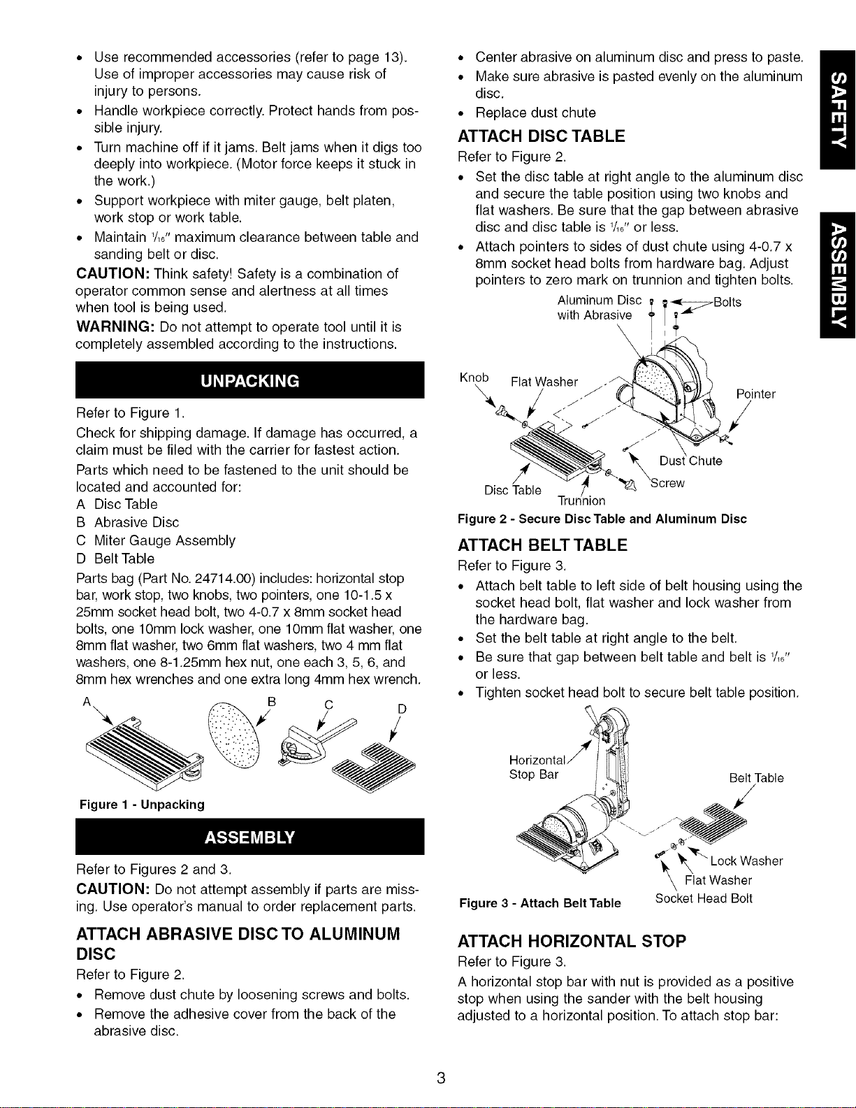
ATTACH DISC TABLE
Refer to Figure 2.
• Set the disc table at right angle to the aluminum disc
and secure the table position using two knobs and
flat washers. Be sure that the gap between abrasive
disc and disc table is 1/1_"or less.
• Attach pointers to sides of dust chute using 4-0.7 x
8mm socket head bolts from hardware bag. Adjust
pointers to zero mark on trunnion and tighten bolts.
Aluminum Disc
with Abrasive
Knob Flat Washer
Pointer
<-
Dus _Chute
Disc Table
Trunnion
Figure 2 - Secure DiscTable and Aluminum Disc
ATTACH BELT TABLE
Refer to Figure 3.
• Attach belt table to left side of belt housing using the
socket head bolt, flat washer and lock washer from
the hardware bag.
• Set the belt table at right angle to the belt.
• Be sure that gap between belt table and belt is 1/1_"
or less.
• Tighten socket head bolt to secure belt table position.
/
H
Figure 1 - Unpacking
Refer to Figures 2 and 3.
CAUTION: Do not attempt assembly if parts are miss-
ing. Use operator's manual to order replacement parts.
ATTACH ABRASIVE DISC TO ALUMINUM
DISC
Refer to Figure 2.
• Remove dust chute by loosening screws and bolts.
• Remove the adhesive cover from the back of the
abrasive disc.
Stop Bar
_I_._FFiat _v°aCkheWrasher
Figure 3 - Attach Belt Table Socket Head Bolt
ATTACH HORIZONTAL STOP
Refer to Figure 3.
A horizontal stop bar with nut is provided as a positive
stop when using the sander with the belt housing
adjusted to a horizontal position. To attach stop bar:
3
Belt Table
• Thread the horizontal stop bar into the threaded hole
on the rear side of belt housing.
• Tighten hex nut.
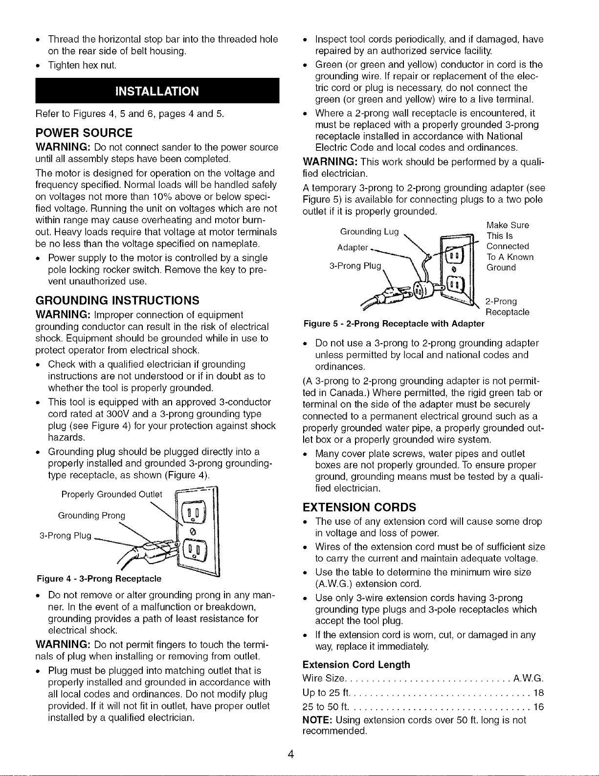
Refer to Figures 4, 5 and 6, pages 4 and 5.
POWER SOURCE
WARNING: Do not connect sander to the power source
until all assembly steps have been completed.
The motor is designed for operation on the voltage and
frequency specified. Normal loads will be handled safely
on voltages not more than 10% above or below speci-
fied voltage. Running the unit on voltages which are not
within range may cause overheating and motor burn-
out. Heavy loads require that voltage at motor terminals
be no less than the voltage specified on nameplate.
• Power supply to the motor is controlled by a single
pole locking rocker switch. Remove the key to pre-
vent unauthorized use.
GROUNDING INSTRUCTIONS
WARNING: Improper connection of equipment
grounding conductor can result in the risk of electrical
shock. Equipment should be grounded while in use to
protect operator from electrical shock.
• Check with a qualified electrician if grounding
instructions are not understood or if in doubt as to
whether the tool is properly grounded.
• This tool is equipped with an approved 3-conductor
cord rated at 300V and a 3-prong grounding type
plug (see Figure 4) for your protection against shock
hazards.
• Grounding plug should be plugged directly into a
properly installed and grounded 3-prong grounding-
type receptacle, as shown (Figure 4).
Properly Grounded Outlet
Grounding Prong
3-Prong
Figure4 - 3-Prong Receptacle
• Do not remove or alter grounding prong in any man-
ner. In the event of a malfunction or breakdown,
grounding provides a path of least resistance for
electrical shock.
WARNING: Do not permit fingers to touch the termi-
nals of plug when installing or removing from outlet.
• Plug must be plugged into matching outlet that is
properly installed and grounded in accordance with
all local codes and ordinances. Do not modify plug
provided. If it will not fit in outlet, have proper outlet
installed by a qualified electrician.
• Inspect tool cords periodically, and if damaged, have
repaired by an authorized service facility.
• Green (or green and yellow) conductor in cord is the
grounding wire. If repair or replacement of the elec-
tric cord or plug is necessary, do not connect the
green (or green and yellow) wire to a live terminal.
• Where a 2-prong wall receptacle is encountered, it
must be replaced with a properly grounded 3-prong
receptacle installed in accordance with National
Electric Code and local codes and ordinances.
WARNING: This work should be performed by a quali-
fied electrician.
A temporary 3-prong to 2-prong grounding adapter (see
Figure 5) is available for connecting plugs to a two pole
outlet if it is properly grounded.
Make Sure
Grounding Lug ..\ _ This Is
Adapter ......_ ..._,'-., _11 Connected
3 Prong Ground
Figure 5 - 2-Prong Receptacle with Adapter
• Do not use a 3-prong to 2-prong grounding adapter
unless permitted by local and national codes and
ordinances.
(A 3-prong to 2-prong grounding adapter is not permit-
ted in Canada.) Where permitted, the rigid green tab or
terminal on the side of the adapter must be securely
connected to a permanent electrical ground such as a
properly grounded water pipe, a properly grounded out-
let box or a properly grounded wire system.
• Many cover plate screws, water pipes and outlet
boxes are not properly grounded. To ensure proper
ground, grounding means must be tested by a quali-
fied electrician.
ToA Known
2-Prong
Receptacle
EXTENSION CORDS
• The use of any extension cord will cause some drop
in voltage and loss of power.
• Wires of the extension cord must be of sufficient size
to carry the current and maintain adequate voltage.
• Use the table to determine the minimum wire size
(A.W.G.) extension cord.
• Use only 3-wire extension cords having 3-prong
grounding type plugs and 3-pole receptacles which
accept the tool plug.
• If the extension cord is worn, cut, or damaged in any
way, replace it immediately.
Extension Cord Length
Wire Size ............................... A.W.G.
Up to 25 ft.................................. 18
25to 50ft .................................. 16
NOTE: Using extension cords over 50 ft. long is not
recommended.
4

MOTOR
The sander is assembled with motor and wiring
installed as an integral part of the tool. The electrical
wiring schematic is shown in Figure 6.
The permanently split capacitor motor has the following
specifications:
Horsepower (Continuous Duty) .................. 1/3
Voltage ................................... 120
Amps ..................................... 3.5
Hertz ..................................... 60
Phase .................................. Single
RPM .................................... 3500
Rotation (viewed from left side) ........... Clockwise
ELECTRICAL CONNECTIONS
WARNING: All electrical connections must be per-
formed by a qualified electrician. Make sure tool is off
and disconnected from power source while motor is
mounted, connected, reconnected or anytime wiring is
inspected.
Motor and wires are installed as shown in wiring dia-
gram (See Figure 6). Motor is assembled with
approved, 3-conductor cord to be used at 120 volts.
Motor is prewired at the factory for 120 volts.
The power lines are inserted directly onto the switch.
The green ground line must remain securely fastened
to the frame to properly protect against electrical shock.
The power supply to the motor is controlled by a single
0ole locking rocker switch.
Switch
_ Motor
Figure 6 -Wiring Schematic
• Remove the key to prevent unauthorized use.
Refer to Figures 7-15.
DESCRIPTION
Craftsman 2 x 6" Belt and Disc Sander has a 2" x 42"
belt and 6" disc for deburring, beveling and sanding
wood, plastic and metal. The sander has a fan-cooled 1/3
HP continuous duty motor. Belt speed is 4400 FPM and
the disc rotates 3500 RPM. The belt table tilts 0 to 90°
and the disc table tilts 0 to 45° for angle sanding. The
quick release tension and tracking mechanism makes
belt changing quick and easy. Belt platen is removable
for contour sanding. Belt housing swivels from vertical
to horizontal for sanding large workpieces. Disc guard
has 11/2"dust collection chute.
SPECIFICATIONS
Belt size .......................... 2 x 42"_ 80 grit
Belt platen area ......................... 2 x 71/4''
Belt table dimensions ..................... 9 x 63A''
Belt table tilts ........................... 0 to 90 °
Belt speed ........................... 4400 FPM
Disc diameter ............................... 6"
Disc table dimensions .................. 83/16x 57/1_''
Disc table tilts ........................... 0 to 45 °
Disc dust chute diameter ..................... lV2"
Disc speed .......................... 3500 RPM
Base dimensions ...................... 91/16x8%2"
Switch ........................ SE Locking rocker
Weight ................................ 30.2 Ibs
WARNING: Operation of any power tool can result in
foreign objects being thrown into the eyes, which can
result in severe eye damage. Always wear safety gog-
gles complying with United States ANSI Z87.1 (shown
on package) before commencing power tool operation.
Safety goggles are available at Sears retail stores or
catalog.
CAUTION: Always observe following safety precautions.
SAFETY PRECAUTIONS
• Whenever adjusting or replacing any parts on the
tool, turn switch OFF and remove the plug from
power source.
• Recheck table knobs. They must be tightened
securely.
• Make sure all guards are properly attached. All
guards should be securely fastened.
• Make sure all moving parts are free and clear of any
interference.
• Make sure all fasteners are tight and have not
vibrated loose.
• With power disconnected, test operation by hand for
clearance and adjust if necessary.
• Always wear eye protection or face shield.
• Make sure abrasive belt always tracks properly.
Correct tracking gives optimum performance.
• After turning switch on, always allow belt to come up
to full speed before sanding or grinding.
• Be sure motor runs clockwise on disc side. Abrasive
belt must travel down.
• Avoid kickback by sanding in accordance with the
directional arrows.
• Keep your hands clear of abrasive belt, disc and all
moving parts.
• For optimum performance, do not stall motor or
reduce speed. Do not force the work into the abrasive.
• Support workpiece with belt table when sanding with
belt, with disc table when sanding with disc.
• Never push a sharp corner of the workpiece rapidly
against the belt or disc. Abrasive backing may tear.
• Replaceabrasiveswhentheybecomeloaded
(glazed)orfrayed.
• Whengrindingmetal,moveworkpieceacrossabra-
sivetopreventheatbuiltup.
• Neverattemptwetsanding.Iftheworkpiece
becomestoohottohandle,coolitinwater.
WARNING:Somedustcreatedbypowersanding,
sawing,grinding,drillingandotherconstructionactivi-
tiescontainschemicalsknowntocausecancer,birth
defectsorotherreproductiveharm.
Someexamplesofthesechemicalsare:
• Leadfromlead-basedpaints.
• Crystallinesilicafrombricksandcementandother
masonryproducts.
• Arsenicandchromiumfromchemically-treatedlumber.
Yourriskfromtheseexposuresvary,dependingonhow
oftenyoudothistypeofwork.Toreduceyourexposure
tothesechemicals:workinawellventilatedareaand
workwithapprovedsafetyequipment.Alwayswear
OSHA/NIOSHapproved,properlyfittingfacemaskor
respiratorwhenusingsuchtools.
MOUNT SANDER
During operation the sander may have a tendency to slide
or move about on the bench or table. It is recommended
to mount the sander onto a stand (see "Recommended
Accessories", page 13) or to a bench top.
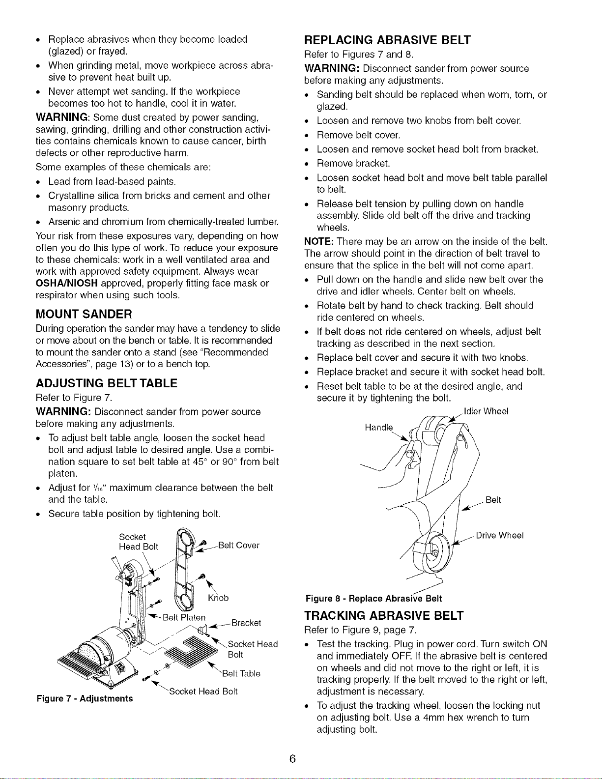
ADJUSTING BELT TABLE
Refer to Figure 7.
WARNING: Disconnect sander from power source
before making any adjustments.
• To adjust belt table angle, loosen the socket head
bolt and adjust table to desired angle. Use a combi-
nation square to set belt table at 45° or 90° from belt
platen.
• Adjust for 1/16"maximum clearance between the belt
and the table.
• Secure table position by tightening bolt.
REPLACING ABRASIVE BELT
Refer to Figures 7 and 8.
WARNING: Disconnect sander from power source
before making any adjustments.
• Sanding belt should be replaced when worn, torn, or
glazed.
• Loosen and remove two knobs from belt cover.
• Remove belt cover.
• Loosen and remove socket head bolt from bracket.
• Remove bracket.
• Loosen socket head bolt and move belt table parallel
to belt.
• Release belt tension by pulling down on handle
assembly. Slide old belt off the drive and tracking
wheels.
NOTE: There may be an arrow on the inside of the belt.
The arrow should point in the direction of belt travel to
ensure that the splice in the belt will not come apart.
• Pull down on the handle and slide new belt over the
drive and idler wheels. Center belt on wheels.
• Rotate belt by hand to check tracking. Belt should
ride centered on wheels.
• If belt does not ride centered on wheels, adjust belt
tracking as described in the next section.
• Replace belt cover and secure it with two knobs.
• Replace bracket and secure it with socket head bolt.
• Reset belt table to be at the desired angle, and
secure it by tightening the bolt.
IdlerWheel
Handle
Belt
Figure 7 - Adjustments
S°CkdeBolt /__BeltCover
"_r---Belt Platen
/..._Bracket
_K.-_ BeltTable
_'Socket Head Bolt
Socket Head
Bolt
Drive Wheel
Figure8 - ReplaceAbrasive Belt
TRACKING ABRASIVE BELT
Refer to Figure 9, page 7.
• Test the tracking. Plug in power cord. Turn switch ON
and immediately OFF. If the abrasive belt is centered
on wheels and did not move to the right or left, it is
tracking properly. If the belt moved to the right or left,
adjustment is necessary.
• To adjust the tracking wheel, loosen the locking nut
on adjusting bolt. Use a 4mm hex wrench to turn
adjusting bolt.
6
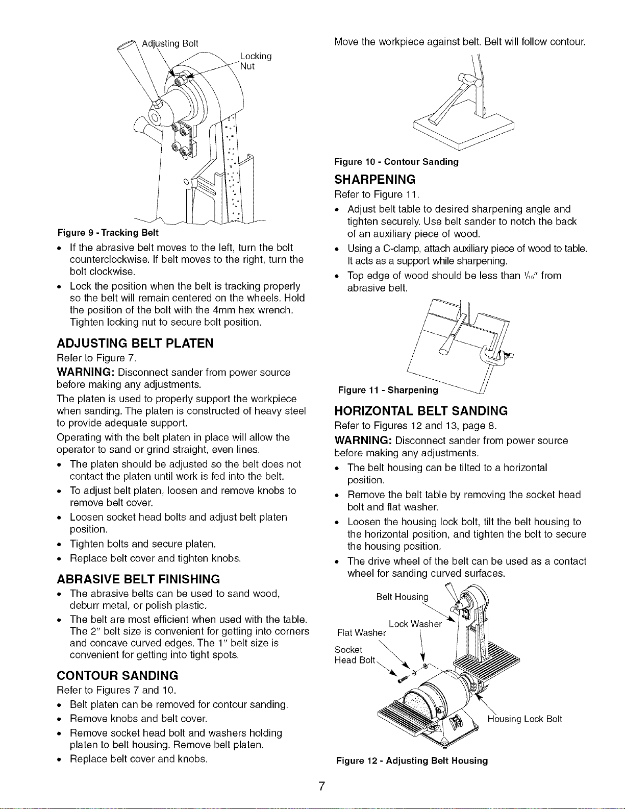
_stingBolt Move the workpiece against belt. Belt will follow contour.
Locking
Figure 9 -Tracking Belt
• If the abrasive belt moves to the left, turn the bolt
counterclockwise. If belt moves to the right, turn the
bolt clockwise.
• Lock the position when the belt is tracking properly
so the belt will remain centered on the wheels. Hold
the position of the bolt with the 4mm hex wrench.
Tighten locking nut to secure bolt position.
Figure 10 - Contour Sanding
SHARPENING
Refer to Figure 11.
• Adjust belt table to desired sharpening angle and
tighten securely. Use belt sander to notch the back
of an auxiliary piece of wood.
• Using a C-clamp, attach auxiliary piece of wood to table.
It acts as a support while sharpening.
• Top edge of wood should be less than 1/161'from
abrasive belt.
ADJUSTING BELT PLATEN
Refer to Figure 7.
WARNING: Disconnect sander from power source
before making any adjustments.
The platen is used to properly support the workpiece
when sanding. The platen is constructed of heavy steel
to provide adequate support.
Operating with the belt platen in place will allow the
operator to sand or grind straight, even lines.
• The platen should be adjusted so the belt does not
contact the platen until work is fed into the belt.
• To adjust belt platen, loosen and remove knobs to
remove belt cover.
• Loosen socket head bolts and adjust belt platen
position.
• Tighten bolts and secure platen.
• Replace belt cover and tighten knobs.
ABRASIVE BELT FINISHING
• The abrasive belts can be used to sand wood,
deburr metal, or polish plastic.
• The belt are most efficient when used with the table.
The 2" belt size is convenient for getting into corners
and concave curved edges. The 1" belt size is
convenient for getting into tight spots.
CONTOUR SANDING
Refer to Figures 7 and 10.
• Belt platen can be removed for contour sanding.
• Remove knobs and belt cover.
• Remove socket head bolt and washers holding
platen to belt housing. Remove belt platen.
• Replace belt cover and knobs.
Figure 11 - Sharpening
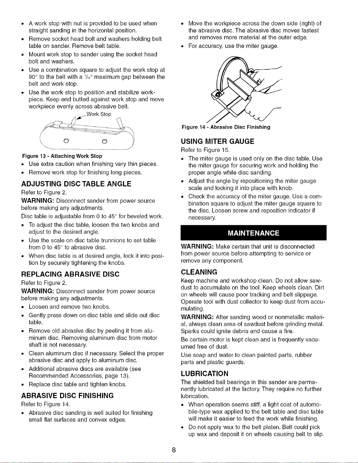
HORIZONTAL BELT SANDING
Refer to Figures 12 and 13, page 8.
WARNING: Disconnect sander from power source
before making any adjustments.
• The belt housing can be tilted to a horizontal
position.
• Remove the belt table by removing the socket head
bolt and flat washer.
• Loosen the housing lock bolt, tilt the belt housing to
the horizontal position, and tighten the bolt to secure
the housing position.
• The drive wheel of the belt can be used as a contact
wheel for sanding curved surfaces.
Belt Housing
Flat Washer /
S°Ckdetolt_ _ "
Housing Lock Bolt
Figure 12 - Adjusting Belt Housing
• A work stop with nut is provided to be used when
straight sanding in the horizontal position.
• Remove socket head bolt and washers holding belt
table on sander. Remove belt table.
• Mount work stop to sander using the socket head
bolt and washers.
• Use a combination square to adjust the work stop at
90° to the belt with a '/,_"maximum gap between the
belt and work stop.
• Use the work stop to position and stabilize work-
piece. Keep end butted against work stop and move
workpiece evenly across abrasive belt.
• Move the workpiece across the down side (right) of
the abrasive disc. The abrasive disc moves fastest
and removes more material at the outer edge.
• For accuracy, use the miter gauge.
__j Work Stop
Figure 13 - Attaching WorkStop
• Use extra caution when finishing very thin pieces.
• Remove work stop for finishing long pieces.
ADJUSTING DISC TABLE ANGLE
Refer to Figure 2.
WARNING: Disconnect sander from power source
before making any adjustments.
Disc table is adjustable from 0 to 45° for beveled work.
• To adjust the disc table, loosen the two knobs and
adjust to the desired angle.
• Use the scale on disc table trunnions to set table
from 0 to 45° to abrasive disc.
• When disc table is at desired angle, lock it into posi-
tion by securely tightening the knobs.
REPLACING ABRASIVE DISC
Refer to Figure 2.
WARNING: Disconnect sander from power source
before making any adjustments.
• Loosen and remove two knobs.
• Gently press down on disc table and slide out disc
table.
• Remove old abrasive disc by peeling it from alu-
minum disc. Removing aluminum disc from motor
shaft is not necessary.
• Clean aluminum disc if necessary. Select the proper
abrasive disc and apply to aluminum disc.
• Additional abrasive discs are available (see
Recommended Accessories, page 13).
• Replace disc table and tighten knobs.
ABRASIVE DISC FINISHING
Refer to Figure 14.
• Abrasive disc sanding is well suited for finishing
small flat surfaces and convex edges.
Figure 14- Abrasive Disc Finishing
USING MITER GAUGE
Refer to Figure 15.
• The miter gauge is used only on the disc table. Use
the miter gauge for securing work and holding the
proper angle while disc sanding.
• Adjust the angle by repositioning the miter gauge
scale and locking it into place with knob.
• Check the accuracy of the miter gauge. Use a com-
bination square to adjust the miter gauge square to
the disc. Loosen screw and reposition indicator if
necessary.
WARNING: Make certain that unit is disconnected
from power source before attempting to service or
remove any component.
CLEANING
Keep machine and workshop clean. Do not allow saw-
dust to accumulate on the tool. Keep wheels clean. Dirt
on wheels will cause poor tracking and belt slippage.
Operate tool with dust collector to keep dust from accu-
mulating.
WARNING: After sanding wood or nonmetallic materi-
al, always clean area of sawdust before grinding metal.
Sparks could ignite debris and cause a fire.
Be certain motor is kept clean and is frequently vacu-
umed free of dust.
Use soap and water to clean painted parts, rubber
parts and plastic guards.
LUBRICATION
The shielded ball bearings in this sander are perma-
nently lubricated at the factory. They require no further
lubrication.
• When operation seems stiff, a light coat of automo-
bile-type wax applied to the belt table and disc table
will make it easier to feed the work while finishing.
• Do not apply wax to the belt platen. Belt could pick
up wax and deposit it on wheels causing belt to slip.
8
 Loading...