

Craftsman 351215100 Owner’s Manual

Operator's Manual
6 x 48" Oscillating Belt
EDGE SANDER
Model No.
351.215100
CAUTION: Read and follow
all Safety Rules and Operating
Instructions before First Use
of this Product.
Sears, Roebuck and Co., Hoffman Estates, IL 60179 U.S.A.
www.sears.com/craftsman
24253.00 Draft (01/23/06)
Warranty ......................................... 2
Safety Rules ...................................... 2
Unpacking ....................................... 3
Assembly ........................................ 3
Installation ...................................... 3-4
Operation ...................................... 4-6
Maintenance ..................................... 6
Troubleshooting ................................... 7
Parts Illustration and List ......................... 8-11
EspaSol ...................................... 12-19
ONE-YEAR FULL WARRANTY ON CRAFTSMAN TOOL
If this Craftsman tool fails due to a defect in material or
workmanship within one year from the date of purchase CALL
1-800-4-MY-HOME® TO ARRANGE FOR FREE REPAIR.
If this tool is used for commercial or rental purposes, this war-
ranty will apply for only ninety days from the date of purchase.
This warranty applies only while this tool is in the United
States.
This warranty gives you specific legal rights and you may also
have other rights, which vary, from state to state.
Sears, Roebuck and Co., Dept. 817WA, Hoffman Estates,
IL 60179
WARNING: For your own safety, read all of the instructions
and precautions before operating tool.
CAUTION: Always follow proper operating procedures as
defined in this manual even if you are familiar with use of this
or similar tools. Remember that being careless for even a
fraction of a second can result in severe personal injury.
BE PREPARED FOR JOB
• Wear proper apparel. Do not wear loose clothing, gloves,
neckties, rings, bracelets or other jewelry which may get
caught in moving parts of machine.
• Wear protective hair covering to contain long hair.
• Wear safety shoes with non-slip soles.
• Wear safety glasses complying with United States ANSI
Z87.1. Everyday glasses have only impact resistant lenses.
They are NOT safety glasses.
• Wear face mask or dust mask if operation is dusty.
• Be alert and think clearly. Never operate power tools when
tired, intoxicated or when taking medications that cause
drowsiness.
PREPARE WORK AREA FOR JOB
* Keep work area clean. Cluttered work areas invite accidents.
* Do not use power tools in dangerous environments. Do not
use power tools in damp or wet locations. Do not expose
power tools to rain.
* Work area should be properly lighted.
* Proper electrical receptacle should be available for tool.
Three prong plug should be plugged directly into properly
grounded, three-prong receptacle.
* Extension cords should have a grounding prong and the three
wires of the extension cord should be of the correct gauge.
* Keep visitors at a safe distance from work area.
* Keep children out of workplace. Make workshop childproof.
Use padlocks, master switches or remove switch keys to
prevent any unintentional use of power tools.
TOOL SHOULD BE MAINTAINED
* Always unplug tool prior to inspection.
* Consult manual for specific maintaining and adjusting
procedures.
* Keep tool lubricated and clean for safest operation.
* Remove adjusting tools. Form habit of checking to see that
adjusting tools are removed before switching machine on.
* Keep all parts in working order. Check to determine that the
guard or other parts will operate properly and perform their
intended function.
* Check for damaged parts. Check for alignment of moving
parts, binding, breakage, mounting and any other condition
that may affect a tool's operation.
* A guard or other part that is damaged should be properly
repaired or replaced. Do not perform makeshift repairs.
(Use parts list provided to order replacement parts.)
KNOW HOW TO USE TOOL
* Use right tool for job. Do not force tool or attachment to do
a job for which it was not designed.
* Disconnect tool when changing abrasive belt.
* Avoid accidental start-up. Make sure that the tool is in the
"OFF" position before plugging in.
* Do not force tool. It will work most efficiently at the rate for
which it was designed.
* Keep hands away from moving parts and sanding surfaces.
* Never leave tool running unattended. Turn the power off
and do not leave tool until it comes to a complete stop.
* Do not overreach. Keep proper footing and balance.
* Never stand on tool. Serious injury could occur if tool is
tipped or if belt is unintentionally contacted.
* Know your tool. Learn the tool's operation, application and
specific limitations.
* Use recommended accessories (refer to page 11). Use of
improper accessories may cause risk of injury to persons.
* Handle the workpiece correctly. Protect hands from possi-
ble injury.
* Turn machine off if it jams. Belt jams when it digs too
deeply into workpiece. (Motor force keeps it stuck in the
work.)
* Support workpiece with miter gauge, belt platen or work
table.
* Maintain V_J'maximum clearance between table and sand-
ing belt.
CAUTION: Think safety! Safety is a combination of operator
common sense and alertness at all times when tool is being
used.
WARNING: Do not attempt to operate tool until it is com-
pletely assembled according to the instructions.
© Sears, Roebuck and Co. 2

° Replace shelf in cabinet.
° Close cabinet door and secure it with knob.
Refer to Figures 4 and 5.
Check for shipping damage. If damage has occurred, a claim
must be filled with carrier. Check for completeness.
Immediately report missing parts to dealer.
The sander comes assembled as one unit. Additional parts
which need to be fastened to sander, should be located and
accounted for before assembling.
• Auxiliary Table (Fig. No. 4, Key No. 56)
• Auxiliary Table Post (Fig. No. 4, Key No. 54)
• Locking Handle (Fig. No. 4, Key No. 52)
• 5/_"-3/8Set Screw (Fig. No. 4, Key No. 55)
° Foot Rest (Fig. No. 5, Key No. 34), 4 each
° 5/_-18 x 1" Hex Head Bolt (Fig. No. 5, Key No. 1), 4 each
° 5/_,,Flat Washer (Fig. No. 5, Key No. 2), 8 each
° 5/_-18" Hex Nut (Fig. No. 5, Key No. 28), 4 each
CAUTION: Do not attempt assembly if parts are missing.
Use this manual to order replacement parts.
Before sander is assembled, a suitable location should be
chosen. The sander with cabinet weighs approximately 200
Ibs when completely assembled. They should be assembled
on location.
• Sander needs to be set on a flat, level surface.
• Make sure there is ample room for moving the workpiece
through the entire cut. There must be enough room that
neither the operator nor the bystanders will have to stand in
line while using the tool.
• Good lighting and correct power supply are also required
for a proper work area.
ATTACH FOOT RESTS
Refer to Figure 5.
Required parts and hardware:
• Four foot rests
• Four %o-18x 1" Hex head bolts
• Eight 5/_o"flat washers
• Four 5/lO"-18Hex nuts
CAUTION: Sander with cabinet weighs approximately
200 Ibs. At least two people are required to attach foot rests.
• Loosen knob (Key No. 32) and open cabinet door (Key No.
31).
• Remove shelf (Key No. 33) from cabinet (Key No. 29).
• Carefully tip the sander to raise cabinet from the floor just
enough so that one foot rest with bolt and washer (Key Nos.
1, 2 and 34) can be positioned under the cabinet corner so
that the bolt slides through the hole on the cabinet base.
Slowly set the sander back to the floor. Repeat three more
times to position one foot rest with bolt, under each cabinet
corner.
• Using the cabinet door opening, secure foot rests to cabinet
using four flat washers and four hex nuts (Key Nos. 2 and
28).
° Make sure all the hex nuts are tight.
ATTACH AUXILIARY TABLE
Refer to Figure 4.
Required parts and hardware:
° Auxiliary table
° Auxiliary table post
° Locking handle
° 5/_-18 x 3/8"Set screw
NOTE: It is not necessary to have the auxiliary table mounted
at all times. Table can be installed only when needed.
* Insert auxiliary table post in auxiliary table (Key Nos. 54
and 56).
° Secure in position with set screw (Key No. 55).
° Slide post into bracket (Key No. 53).
° Secure in position with locking handle (Key No. 52).
Refer to Figures 1, 2, and 3, pages 4 and 5.
Sander comes with the motor and wiring installed. The
110/220-volt AC induction motor has the following specifica-
tions.
Horsepower (Continuous duty) ...................... 3/4
Amperes ................................... 10.0/5.0
Frequency ................................... 60 HZ
Phase ....................................... Single
RPM ......................................... 1720
Prewired ..................................... 110V
WARNING: All electrical connections must be performed by
a qualified electrician.
WARNING: Do not connect sander to the power source until
all assembly steps have been completed.
POWER SOURCE
The motor is designed for operation on the voltage and fre-
quency specified. Normal loads will be handled safely on volt-
ages not more than 10% above or below specified voltage.
Running the unit on voltages which are not within the range
may cause overheating and motor burn-out. Heavy loads
require that the voltage at motor terminals be no less than the
voltage specified on nameplate.
° Power supply to the motor is controlled by a single pole
locking rocker switch. Remove the key to prevent unautho-
rized use.
GROUNDING INSTRUCTIONS
WARNING: Improper connection of equipment grounding
conductor can result in the risk of electrical shock. Equipment
should be grounded while in use to protect operator from
electrical shock.
* Check with a qualified electrician if grounding instructions
are not understood or if in doubt as to whether the tool is
properly grounded.
* This tool is equipped with an approved 3-conductor cord
rated at 240V and a 3-prong grounding type plug rated at
125V (Figure 1) for your protection against shock hazards.
D
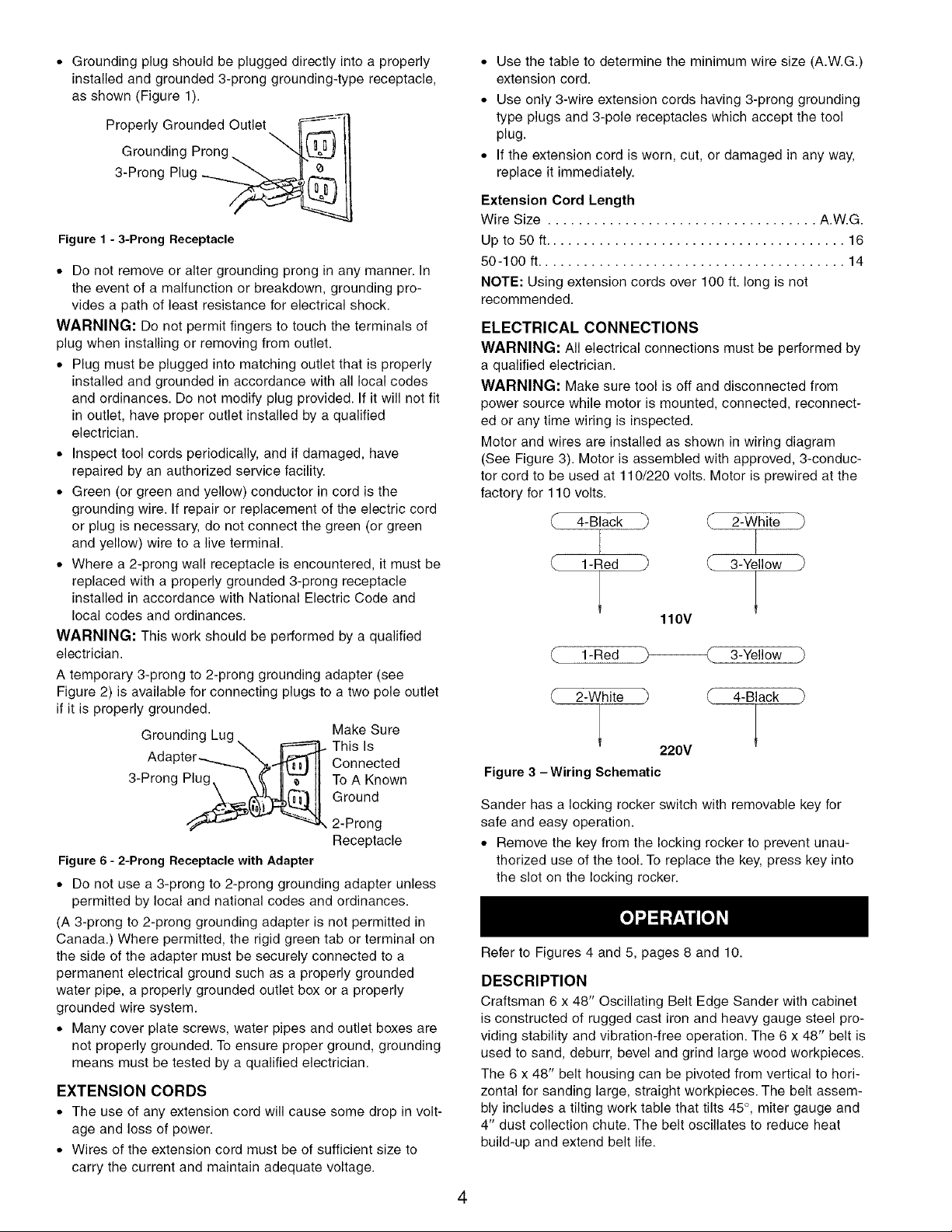
* Groundingplugshouldbepluggeddirectlyintoaproperly
installedandgrounded3-pronggrounding-typereceptacle,
asshown(Figure1).
GroundingProng.
° Use the table to determine the minimum wire size (A.W.G.)
extension cord.
° Use only 3-wire extension cords having 3-prong grounding
type plugs and 3-pole receptacles which accept the tool
plug.
° If the extension cord is worn, cut, or damaged in any way,
replace it immediately.
3-ProngPlug,__'_
Figure 1 - 3-Prong Receptacle
* Do not remove or alter grounding prong in any manner. In
the event of a malfunction or breakdown, grounding pro-
vides a path of least resistance for electrical shock.
WARNING: Do not permit fingers to touch the terminals of
plug when installing or removing from outlet.
* Plug must be plugged into matching outlet that is properly
installed and grounded in accordance with all local codes
and ordinances. Do not modify plug provided. If it will not fit
in outlet, have proper outlet installed by a qualified
electrician.
* Inspect tool cords periodically, and if damaged, have
repaired by an authorized service facility.
* Green (or green and yellow) conductor in cord is the
grounding wire. If repair or replacement of the electric cord
or plug is necessary, do not connect the green (or green
and yellow) wire to a live terminal.
* Where a 2-prong wall receptacle is encountered, it must be
replaced with a properly grounded 3-prong receptacle
installed in accordance with National Electric Code and
local codes and ordinances.
WARNING: This work should be performed by a qualified
electrician.
A temporary 3-prong to 2-prong grounding adapter (see
Figure 2) is available for connecting plugs to a two pole outlet
if it is properly grounded.
Grounding Lug, _ Make Sure
Adapter.-._......_%_ CnlsnlScted
3-Prong Plug, \(_(_ IILZ'_IIToAKnown
Ground
_ 2-Prong
Receptacle
Figure 6- 2-Prong Receptaclewith Adapter
° Do not use a 3-prong to 2-prong grounding adapter unless
permitted by local and national codes and ordinances.
(A 3-prong to 2-prong grounding adapter is not permitted in
Canada.) Where permitted, the rigid green tab or terminal on
the side of the adapter must be securely connected to a
permanent electrical ground such as a properly grounded
water pipe, a properly grounded outlet box or a properly
grounded wire system.
* Many cover plate screws, water pipes and outlet boxes are
not properly grounded. To ensure proper ground, grounding
means must be tested by a qualified electrician.
EXTENSION CORDS
* The use of any extension cord will cause some drop in volt-
age and loss of power.
* Wires of the extension cord must be of sufficient size to
carry the current and maintain adequate voltage.
Extension Cord Length
Wire Size ................................... A.W.G.
Up to 50 ft....................................... 16
50-100 ft........................................ 14
NOTE: Using extension cords over 100 ft. long is not
recommended.
ELECTRICAL CONNECTIONS
WARNING: All electrical connections must be performed by
a qualified electrician.
WARNING: Make sure tool is off and disconnected from
power source while motor is mounted, connected, reconnect-
ed or any time wiring is inspected.
Motor and wires are installed as shown in wiring diagram
(See Figure 3). Motor is assembled with approved, 3-conduc-
tor cord to be used at 110/220 volts. Motor is prewired at the
factory for 110 volts.
4-Black ) 2-White
1-Red P (._ 3-Yellow
110V
1-Red _ 3-Yellow
2-White 4-Black
220V
Figure 3 -Wiring Schematic
Sander has a locking rocker switch with removable key for
safe and easy operation.
° Remove the key from the locking rocker to prevent unau-
thorized use of the tool. To replace the key, press key into
the slot on the locking rocker.
Refer to Figures 4 and 5, pages 8 and 10.
DESCRIPTION
Craftsman 6 x 48" Oscillating Belt Edge Sander with cabinet
is constructed of rugged cast iron and heavy gauge steel pro-
viding stability and vibration-free operation. The 6 x 48" belt is
used to sand, deburr, bevel and grind large wood workpieces.
The 6 x 48" belt housing can be pivoted from vertical to hori-
zontal for sanding large, straight workpieces. The belt assem-
bly includes a tilting work table that tilts 45 °, miter gauge and
4" dust collection chute. The belt oscillates to reduce heat
build-up and extend belt life.
4

The 3" diameter idler drum and the auxiliary table permit the
sanding of contoured shapes.
The dust collection chute accepts the standard 4" dust collec-
tion hose for quick removal of dust.
SPECIFICATIONS
Belt size ............................. 6 x 48", 100 grit
Belt platen area ............................ 6% x 167/8''
Belt table dimensions ....................... 63/4x 13V2"
Belt table tilts ............................... 0° to 45°
Belt housing tilts ............................ 0° to 90°
Dust chute diameter ............................... 4"
Belt speed ................................ 1350 FPM
Belt oscillation speed .................. 7.5 cycles/minute
Auxiliary table size .......................... 4V4x 73/4"
Overall dimensions ....................... 45 x 29 x 17"
Switch .................... 120 Volts, SP, Locking rocker
Motor ............................... 3/4HP1720 RPM
............................ 110/220V, 10.0/5.0 AMPS
Weight ..................................... 198 Ibs
WARNING: Operation of any power tool can result in foreign
objects being thrown into eyes which can result in severe eye
damage. Always wear safety goggles complying with United
States ANSI Z87.1 (shown on package) before commencing
power tool operation. Safety goggles are available at Sears
retail stores or catalog.
CAUTION: Always observe the following safety precautions.
SAFETY PRECAUTIONS
• Whenever adjusting or replacing any parts on the tool, turn
switch OFF and remove the plug from power source.
• Recheck table handles. They must be tightened securely.
• Make sure all guards are properly attached. All guards
should be securely fastened.
• Make sure all moving parts are free and clear of any
interference.
• Make sure all fasteners are tight and have not vibrated
loose.
• With power disconnected, test operation by hand to verify
clearance and adjust if necessary.
• Always wear eye protection or face shield.
• Make sure abrasive belt tracks properly. Correct tracking
gives optimum performance.
• After turning switch on, always allow belt to come up to full
speed before sanding or grinding.
• Keep your hands clear of abrasive belt and all moving
parts.
• For optimum performance, do not stall motor or reduce
speed. Do not force the work into the abrasive.
• Support workpiece with table when sanding with belt.
• Never push a sharp corner of the workpiece rapidly against
belt. Abrasive backing may tear.
• Replace abrasives when they become loaded (glazed) or
frayed.
WARNING: Some dust created by power sanding, sawing,
grinding, drilling and other construction activities contains
chemicals known to cause cancer, birth defects or other
reproductive harm.
Some examples of these chemicals are:
° Lead from lead-based paints.
° Crystalline silica from bricks and cement and other mason-
ry products.
° Arsenic and chromium from chemically-treated lumber.
Your risk from these exposures vary, depending on how often
you do this type of work. To reduce your exposure to these
chemicals: work in a well ventilated area and work with
approved safety equipment. Always wear MSHA/NIOSH
approved, properly fitting face mask or respirator when using
such tools.
ABRASIVE BELT FINISHING
° Finishing flat surfaces: Hold workpiece firmly with both
hands; keep fingers away from abrasive belt.
Use work stop. Work stop is used to position and secure
work being sanded. Keep end butted against work stop and
move work evenly across abrasive belt. Use extra caution
when finishing very thin pieces.
Finishing long pieces: remove work stop. Apply only
enough pressure to allow abrasive belt to remove material.
° Finishing curved edges: Finish outside curves on flat por-
tion of abrasive belt. Finish inside curves on idler drum por-
tion of abrasive belt.
° Finishing end grain: It is more convenient to finish ends of
long workpieces with the abrasive belt in a vertical position.
° For accuracy use miter gauge.
° Adjust belt table angle for beveled work.
° Belt oscillation may be stopped by pulling on black washer
on gearbox assembly. Press in on washer to restart oscilla-
tion. Do not ajdust belt tracking with oscillation stopped.
USING MITER GAUGE
Refer to Figure 5.
° Use the miter gauge for securing the work and holding the
proper angle while sanding.
° Adjust angle by repositioning the miter gauge (Key No. 15).
Loosen the knob (Key No. 17) to reposition miter gauge.
° Tighten the knob to secure miter gauge position.
° Use a combination square to adjust miter gauge square to
belt. Scale should be at zero. Loosen screw (Key No. 13)
and reposition pointer (Key No. 12) if necessary.
ADJUSTING BELT HOUSING
Refer to Figure 5.
The belt housing can be positioned at a full vertical position, a
full horizontal position, or at any angle in between which is
convenient for the sanding operation.
To adjust belt housing position:
° Loosen locking handle (Key No. 3).
° Push belt housing to move to the desired angle.
° A positive stop bolt (Key No. 27) is provided to stop the belt
housing at the full horizontal position.
° Tighten locking handle to secure belt housing position.
TABLE ADJUSTMENT
Refer to Figure 5.
° To move table vertically, loosen locking handle (Key No.
37). Reposition table and secure in position.
• Tomovetabletowardorawayfrombelt,loosentwosocket
headbolts(KeyNo.9)intable,repositiontableandsecure
inposition.
• Tochangeangleoftable,loosenlockinghandle(KeyNo.
22),tilttabletodesiredangleusingscale(KeyNo.24)and
secureinposition.
HORIZONTAL BELT SANDING
Refer to Figure 4.
• Adjust the belt housing to full horizontal position as
described in the above section, "Adjusting Belt Housing".
• Idler drum (Key No. 3) can be used as a contact drum to
sand curved surfaces.
USING AUXILIARY TABLE
When using the idler drum for contour sanding, it is recom-
mended that the auxiliary table be positioned so that the
workpiece will be at the center of the idler drum. This will
assure proper belt tracking and prevent the edge of the work-
piece from becoming tapered.
NOTE: Use auxiliary table only with belt housing in vertical
position.
BELT TRACKING
Refer to Figure 4.
Belt (Key No. 59) should oscillate around center on drive and
idler drums (Key Nos. 3 and 35). The sander is shipped with
the tracking mechanism properly adjusted. However, if adjust-
ment is necessary:
• Turn the unit on.
• Insert a _/8"or %2"hex wrench into the hole on adjusting nut
(Key No. 13) on either side.
• Turn the adjusting nut to the right to move belt toward you
or turn the adjusting nut to the left to move belt away from
you.
• Turn the unit off.
REPLACING BELT
Refer to Figure 4.
• Sanding belt must be replaced when worn, torn, or glazed.
• Turn the belt tension handle toward drive drum (Key No. 16)
to release belt tension.
• Loosen and remove four knobs (Key No. 61) from the rear
of the sander.
• Remove belt cover (Key No. 60).
• Slide old belt off the drive and idler drums (Key Nos. 3 and
35).
NOTE: There may be an arrow on the inside of the belt. The
arrow should point in direction of rotation to ensure that the
splice in the belt will not come apart.
• Slide new belt over the drive and idler drums; center belt on
drums.
• Push the belt tension handle toward the idler drum to
tension belt.
• Replace belt cover using knobs.
• Wear a protective glove and manually rotate the belt by
hand to check tracking. If tracking needs to be adjusted,
follow steps described in "Belt Tracking".
WARNING: Make certain that the unit is disconnected from
power source before attempting to service or remove any
component.
CLEANING
Keep machine and workshop clean. Do not allow sawdust to
accumulate on the tool. Keep the drums clean. Dirt on drums
will cause poor tracking and belt slippage. Operate tool with
dust collector to keep dust from accumulating.
Be certain motor is kept clean and is frequently vacuumed
free of dust.
Use soap and water to clean painted parts, rubber parts and
plastic guards.
LUBRICATION
The shielded ball bearings in this tool are permanently lubri-
cated at the factory. They require no further lubrication.
• When operation seems stiff, a light coat of paste wax
applied to the tables will make it easier to feed the work
while finishing.
• Do not apply wax to the belt platen. Belt could pick up wax
and deposit it on the drums causing belt to slip.
• Periodically use a grease gun to add grease to gearbox
assembly through grease nipple.
KEEP TOOL IN REPAIR
° If power cord is worn, cut, or damaged in any way, have it
replaced immediately.
• Replace worn abrasives when needed.
• Replace any damaged or missing parts. Use parts list to
order parts.
Any attempt to repair motor may create a hazard unless
repair is done by a qualified service technician. Repair service
is available at your nearest Sears store.
6
 Loading...