

Craftsman 351214610 Owner’s Manual

Operator's Manual
®
10"
TILTING HEAD BENCH TOP
BAND SAW WITH DUST COLLECTION
Model No.
351.214610
\
\
\
\
\
CAUTION: Read and follow
all Safety Rules and Operating
Instructions before First Use
of this Product.
Sears, Roebuck and Co., Hoffman Estates, IL 60179 U.S.A.
www.sears.com/craftsman
23563.00 Draft (03/18/05)
Warranty.................................... 2
SafetyRules............................... 2-3
Unpacking.................................. 3
Assembly................................... 3
Installation................................. 4-5
Operation................................. 5-9
Maintenance................................. 9
Troubleshooting............................. 11
PartsIllustrationsandLists.................. 12-15
EspaSol................................. 16-24
FULL ONE YEAR WARRANTY
Ifthis productfailsdue to a defect inmaterialorworkmanship
withinone yearfrom thedate of purchase,Searswill at itsoption
repairor replaceitfreeof charge.Contactyour nearestSears
ServiceCenter (1-800-4-MY-HOME)toarrangefor product
repair,or returnthis productto place ofpurchasefor replacement.
Ifthis productisused for commercialor rental purposes,thiswar-
rantywillapplyfor90 daysfrom thedate of purchase.
Thiswarrantyappliesonlywhile thisproductis used in theUnited
States.
Thiswarrantygivesyou specificlegalrightsand youmay also
haveother rightswhich vary from stateto state.
Sears, Roebuck and Co., Dept. 817WA, Hoffman
Estates, IL 60179
WARNING: For your own safety, read all of the
instructions and precautions before operating tool.
CAUTION: Always follow proper operating procedures
as defined in this manual -- even if you are familiar
with use of this or similar tools. Remember that being
careless for even a fraction of a second can result in
severe personal injury.
BE PREPARED FOR JOB
• Wear proper apparel. Do not wear loose clothing,
gloves, neckties, rings, bracelets or other jewelry
which may get caught in moving parts of machine.
• Wear protective hair covering to contain long hair.
• Wear safety shoes with non-slip soles.
• Wear safety glasses complying with United States
ANSI Z87.1. Everyday glasses have only impact
resistant lenses. They are NOT safety glasses.
• Wear face mask or dust mask if operation is dusty.
• Be alert and think clearly. Never operate power tools
when tired, intoxicated or when taking medications
that cause drowsiness.
PREPARE WORK AREA FOR JOB
• Keep work area clean. Cluttered work areas invite
accidents.
• Do not use power tools in dangerous environments.
Do not use power tools in damp or wet locations. Do
not expose power tools to rain.
• Work area should be properly lighted.
• Proper electrical receptacle should be available for
tool. Three-prong plug should be plugged directly
into properly grounded, three-prong receptacle.
• Extension cords should have a grounding prong and
the three wires of the extension cord should be of
the correct gauge.
• Keep visitors at a safe distance from work area.
• Keep children out of workplace. Make workshop
childproof. Use padlocks, master switches or remove
switch keys to prevent any unintentional use of
power tools.
TOOL SHOULD BE MAINTAINED
• Always unplug tool prior to inspection.
• Consult manual for specific maintaining and adjust-
ing procedures.
• Keep tool lubricated and clean for safest operation.
• Remove adjusting tools. Form habit of checking to
see that adjusting tools are removed before switch-
ing machine on.
• Keep all parts in working order. Check to determine
that the guard or other parts will operate properly
and perform their intended function.
• Check for damaged parts. Check for alignment of
moving parts, binding, breakage, mounting and any
other condition that may affect a tool's operation.
• A guard or other part that is damaged should be
properly repaired or replaced. Do not perform
makeshift repairs. (Use parts list provided to order
replacement parts.)
KNOW HOW TO USE TOOL
• Use right tool for job. Do not force tool or attachment
to do a job for which it was not designed.
• Disconnect tool when changing blade.
• Avoid accidental start-up. Make sure that the tool is
in the OFF position before plugging in.
• Do not force tool. It will work most efficiently at the
rate for which it was designed.
• Keep hands away from moving parts and cutting
surfaces.
• Never leave tool running unattended. Turn the power
off and do not leave tool until it comes to a complete
stop.
• Do not overreach. Keep proper footing and balance.
© Sears, Roebuck and Co. 2
• Never stand on tool. Serious injury could occur if tool
is tipped or if blade is unintentionally contacted.
• Know your tool. Learn the tool's operation, applica-
tion and specific limitations.
• Use recommended accessories (refer to page 15).
Use of improper accessories increases the risk of
injury to persons.
• Handle workpiece correctly. Protect hands from pos-
sible injury.
• Turn machine off if it jams. Blade jams when it digs
too deeply into workpiece. (Motor force keeps it
stuck in the work.) Do not remove jammed or cut off
pieces until the saw is turned off, unplugged and the
blade has stopped.
WARNING: The operation of any power tool can result in
foreign objects being thrown into the eyes, which can
result in severe eye damage. Always wear safety goggles
complying with United States ANSI Z87.1 (shown on
package) before commencing power tool operation.
Safety goggles are available through your Sears catalog.
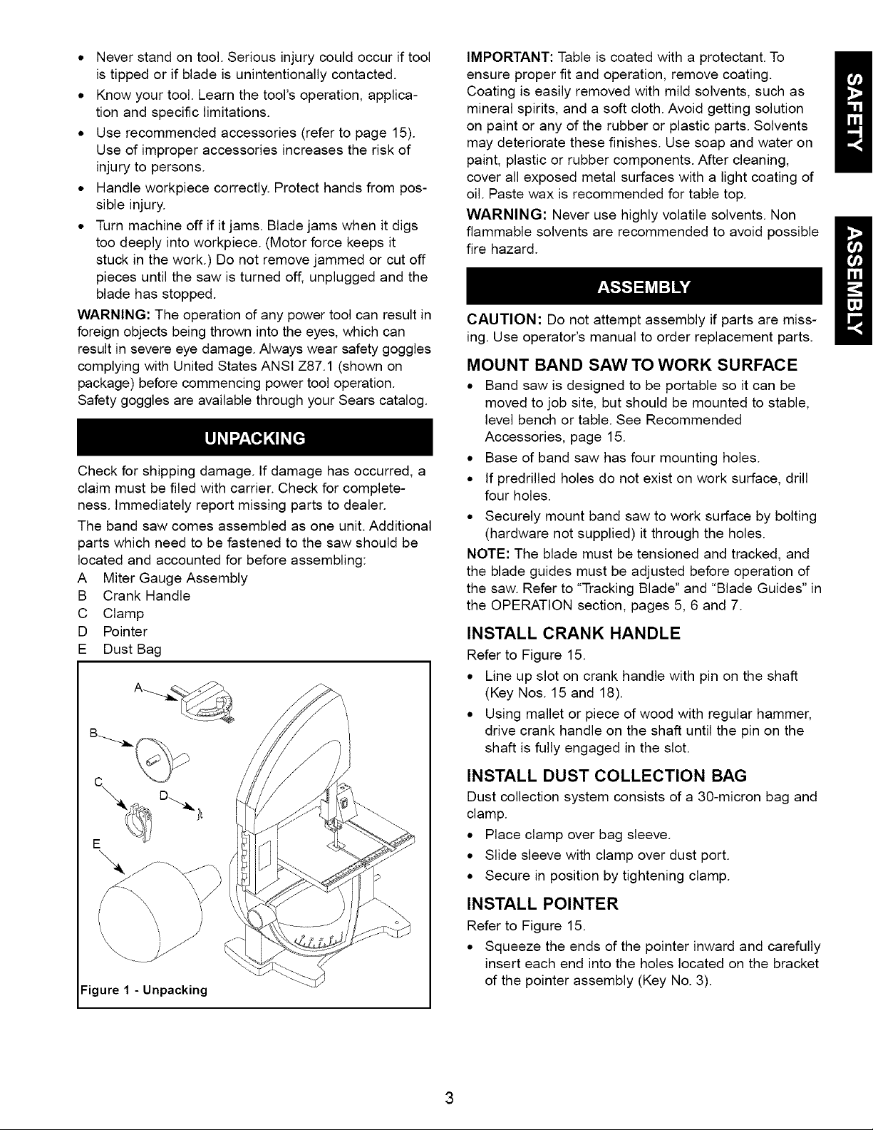
Check for shipping damage. If damage has occurred, a
claim must be filed with carrier. Check for complete-
ness. Immediately report missing parts to dealer.
The band saw comes assembled as one unit. Additional
parts which need to be fastened to the saw should be
located and accounted for before assembling:
A Miter Gauge Assembly
B Crank Handle
C Clamp
D Pointer
E Dust Bag
IMPORTANT: Table is coated with a protectant. To
ensure proper fit and operation, remove coating.
Coating is easily removed with mild solvents, such as
mineral spirits, and a soft cloth. Avoid getting solution
on paint or any of the rubber or plastic parts. Solvents
may deteriorate these finishes. Use soap and water on
paint, plastic or rubber components. After cleaning,
cover all exposed metal surfaces with a light coating of
oil. Paste wax is recommended for table top.
WARNING: Never use highly volatile solvents. Non
flammable solvents are recommended to avoid possible
fire hazard.
CAUTION: Do not attempt assembly if parts are miss-
ing. Use operator's manual to order replacement parts.
MOUNT BAND SAW TO WORK SURFACE
• Band saw is designed to be portable so it can be
moved to job site, but should be mounted to stable,
level bench or table. See Recommended
Accessories, page 15.
• Base of band saw has four mounting holes.
• If predrilled holes do not exist on work surface, drill
four holes.
• Securely mount band saw to work surface by bolting
(hardware not supplied) it through the holes.
NOTE: The blade must be tensioned and tracked, and
the blade guides must be adjusted before operation of
the saw. Refer to "Tracking Blade" and "Blade Guides" in
the OPERATION section, pages 5, 6 and 7.
INSTALL CRANK HANDLE
Refer to Figure 15.
• Line up slot on crank handle with pin on the shaft
(Key Nos. 15 and 18).
• Using mallet or piece of wood with regular hammer,
drive crank handle on the shaft until the pin on the
shaft is fully engaged in the slot.
Figure I - Unpacking
INSTALL DUST COLLECTION BAG
Dust collection system consists of a 30-micron bag and
clamp.
• Place clamp over bag sleeve.
• Slide sleeve with clamp over dust port.
• Secure in position by tightening clamp.
INSTALL POINTER
Refer to Figure 15.
• Squeeze the ends of the pointer inward and carefully
insert each end into the holes located on the bracket
of the pointer assembly (Key No. 3).
RefertoFigures2and3.
MOTOR
The 115 Volt AC motor has the following specifications:
Horsepower (Maximum Developed) ............. 1.0
Voltage ................................... 115
Amps ..................................... 4.6
Hertz ..................................... 60
Phase .................................. Single
RPM .................................... 1725
POWER SOURCE
The motor is designed for operation on the voltage and
frequency specified. Normal loads will be handled safe-
ly on voltages not more than 10% above or below the
specified voltage.
Running the unit on voltages which are not within the
range may cause overheating and motor burn-out.
Heavy loads require that the voltage at motor terminals
be no less than the voltage specified. Power supply to
the motor is controlled by a double pole locking rocker
switch. Remove the key to prevent unauthorized use.
Plug must be plugged into matching outlet that is prop-
erly installed and grounded in accordance with all local
codes and ordinances. Do not modify plug provided. If it
will not fit in outlet, have proper outlet installed by a
qualified electrician.
Inspect tool cords periodically, and if damaged, have
them repaired by an authorized service facility.
Green (or green and yellow) conductor in cord is the
grounding wire. If repair or replacement of the electric
cord or plug is necessary, do not connect the green (or
green and yellow) wire to a live terminal.
Where a 2-prong wall receptacle is encountered, it
must be replaced with a properly grounded 3-prong
receptacle installed in accordance with National Electric
Code and local codes and ordinances.
WARNING: This work should be performed by a quali-
fied electrician.
A temporary 3-prong to 2-prong grounding adapter (see
Figure 3) is available for connecting plugs to a two pole
outlet if it is properly grounded.
Grounding Lug
Adapter This Is
"_._ Make Sure
GROUNDING INSTRUCTIONS
WARNING: Improper connection of equipment
grounding conductor can result in the risk of electrical
shock. Equipment should be grounded while in use to
protect operator from electrical shock.
Check with a qualified electrician if grounding instruc-
tions are not understood or if in doubt as to whether the
tool is properly grounded.
This tool is equipped with an approved 3 conductor
cord rated at 150V and a three prong grounding type
plug for your protection against shock hazards.
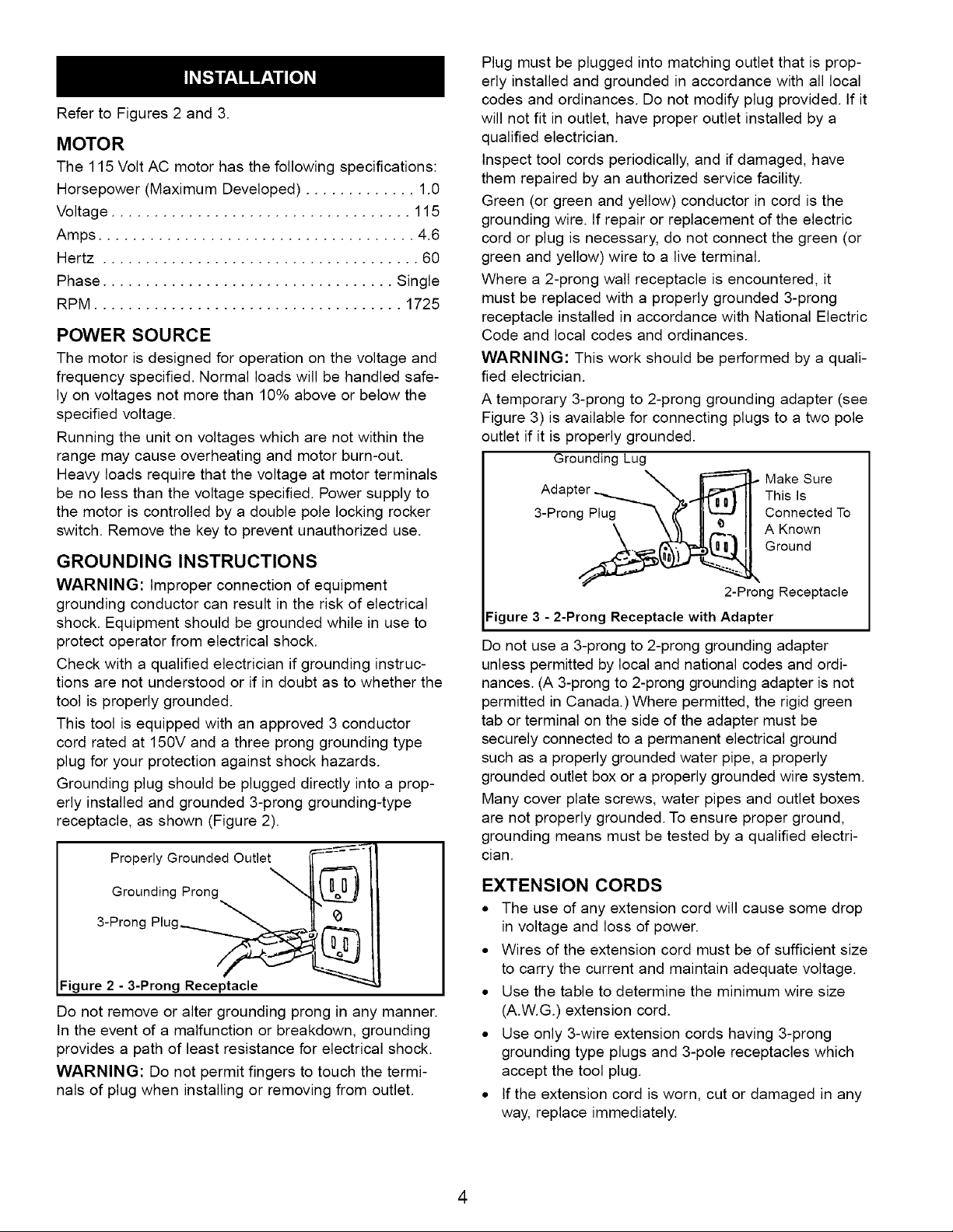
Grounding plug should be plugged directly into a prop-
erly installed and grounded 3-prong grounding-type
receptacle, as shown (Figure 2).
Properly Grounded Outlet
Grounding Prong
3-Prong Plug__
Figure 2 - 3-Prong Receptacle
Do not remove or alter grounding prong in any manner.
In the event of a malfunction or breakdown, grounding
provides a path of least resistance for electrical shock.
WARNING: Do not permit fingers to touch the termi-
nals of plug when installing or removing from outlet.
3-Pr°ng_..i ._ AGroundC°nnectedKnownTo
2-Prong Receptacle
Figure 3 - 2-Prong Receptacle with Adapter
Do not use a 3-prong to 2-prong grounding adapter
unless permitted by local and national codes and ordi-
nances. (A 3-prong to 2-prong grounding adapter is not
permitted in Canada.) Where permitted, the rigid green
tab or terminal on the side of the adapter must be
securely connected to a permanent electrical ground
such as a properly grounded water pipe, a properly
grounded outlet box or a properly grounded wire system.
Many cover plate screws, water pipes and outlet boxes
are not properly grounded. To ensure proper ground,
grounding means must be tested by a qualified electri-
cian.
EXTENSION CORDS
• The use of any extension cord will cause some drop
in voltage and loss of power.
• Wires of the extension cord must be of sufficient size
to carry the current and maintain adequate voltage.
• Use the table to determine the minimum wire size
(A.W.G.) extension cord.
• Use only 3-wire extension cords having 3-prong
grounding type plugs and 3-pole receptacles which
accept the tool plug.
• If the extension cord is worn, cut or damaged in any
way, replace immediately.
4
EXTENSION CORD LENGTH
Wire Size A.W.G.
Up to 50 ft.................................. 16
NOTE: Using extension cords over 50 ft. long is not
recommended.
Refer to Figures 4 - 13, pages 5-8.
The Craftsman 10" Tilting Head Band Saw features alu-
minum frame construction and a solid cast iron table
surface to insure durability. It is designed for cutting
hard and soft woods, as well as nonferrous metals and
plastics. Head of the saw tilts from 90° to 45° while the
table remains in horizontal position for straight line
feeding of the material. The saw is equipped with a
miter gauge for performing many different operations.
The built-in dust collection system helps to keep the
worksurface clean. A convenient quick tensioning and
comprehensive tracking mechanism makes blade
changing quick and easy.
SPECIFICATIONS
Depth of throat at 90° . ...................... 9%"
Maximum depth of cut at 90 ° . .................. 5"
Depth of throat at 45 ° . ........ 7'/4"for 1" thick board
4" for 3" thick board
Maximum depth of cut at 45 °. ................. 3W'
Table size .......................... 13_/2x 11V2"
Head tilt .............................. 0° to 45 °
Wheel diameter ............................. 8"
Blade length .............................. 63_/Z'
Blade range ........................ 63V6- 639/_c,''
Blade width ............................. '/4- 3/j,
Blade speed ......................... 3600 FPM
Overall dimensions .................. 29 x 16 x 34"
Shipping weight .......................... 95 Ibs
Dust collection port ......................... 21/2"
CAUTION: Always observe the following safety
precautions:
• Make sure that blade guides and thrust bearings are
positioned and adjusted correctly to prevent side-
ways and rearward movement of the blade. Adjust
upper guide to just clear workpiece.
• Check to make sure blade is tensioned and tracking
properly. Do not over tension the blade in order to
prevent premature blade wear and breakage. Avoid
under tensioning to eliminate back and forth, side to
side blade movement as it cuts.
• Use proper blade for the cutting operation.
• After turning saw on, allow blade to come to full
speed before attempting any cutting operation.
• Support workpiece properly and use a smooth
steady feed to guide work through the cut. Use push
sticks or push blocks when required.
• Keep hands away and out of line with moving parts.
• Always wear eye protection.
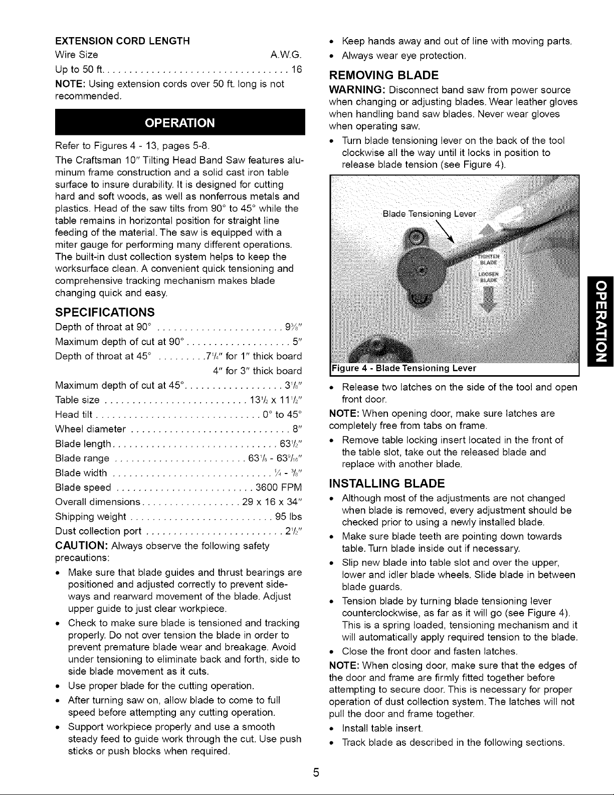
REMOVING BLADE
WARNING: Disconnect band saw from power source
when changing or adjusting blades. Wear leather gloves
when handling band saw blades. Never wear gloves
when operating saw.
• Turn blade tensioning lever on the back of the tool
clockwise all the way until it locks in position to
release blade tension (see Figure 4).
Blade Tensioning I
Figure 4 - Blade Tensioning Lever
• Release two latches on the side of the tool and open
front door.
NOTE: When opening door, make sure latches are
completely free from tabs on frame.
• Remove table locking insert located in the front of
the table slot, take out the released blade and
replace with another blade.
INSTALLING BLADE
• Although most of the adjustments are not changed
when blade is removed, every adjustment should be
checked prior to using a newly installed blade.
• Make sure blade teeth are pointing down towards
table. Turn blade inside out if necessary.
• Slip new blade into table slot and over the upper,
lower and idler blade wheels. Slide blade in between
blade guards.
• Tension blade by turning blade tensioning lever
counterclockwise, as far as it will go (see Figure 4).
This is a spring loaded, tensioning mechanism and it
will automatically apply required tension to the blade.
• Close the front door and fasten latches.
NOTE: When closing door, make sure that the edges of
the door and frame are firmly fitted together before
attempting to secure door. This is necessary for proper
operation of dust collection system. The latches will not
pull the door and frame together.
• Install table insert.
• Track blade as described in the following sections.
TRACKING BLADE
WARNING: Be very careful; improperly tracked blade
may spring out from wheels causing serious injury. Do
not perform tracking adjustment while band saw is
running.
• Disconnect band saw from power source.
• To check the blade tracking, rotate drive wheel by
hand in clockwise direction.
• Proper tracking is achieved when drive and idler
wheels are aligned. Tracking plate (see Figure 5) on
the back of the tool frame is used to tilt upper idler
wheel and align all three blade wheels.
Hex Nut
Figure 5 -Tracking Plate
• Loosen up hex nut.
• Loosen up socket head bolts. There are four socket
head bolts holding tracking plate. Bottom socket
head bolts should be loosened just enough to allow
tilting of the plate. If the bottom socket head bolt is
loosened too much, the plate will not tilt.
• Using set screws, tilt the plate in vertical (up and
down) plane until proper tracking is achieved. Upper
idler blade wheel tilts in the same direction as track-
ing plate.
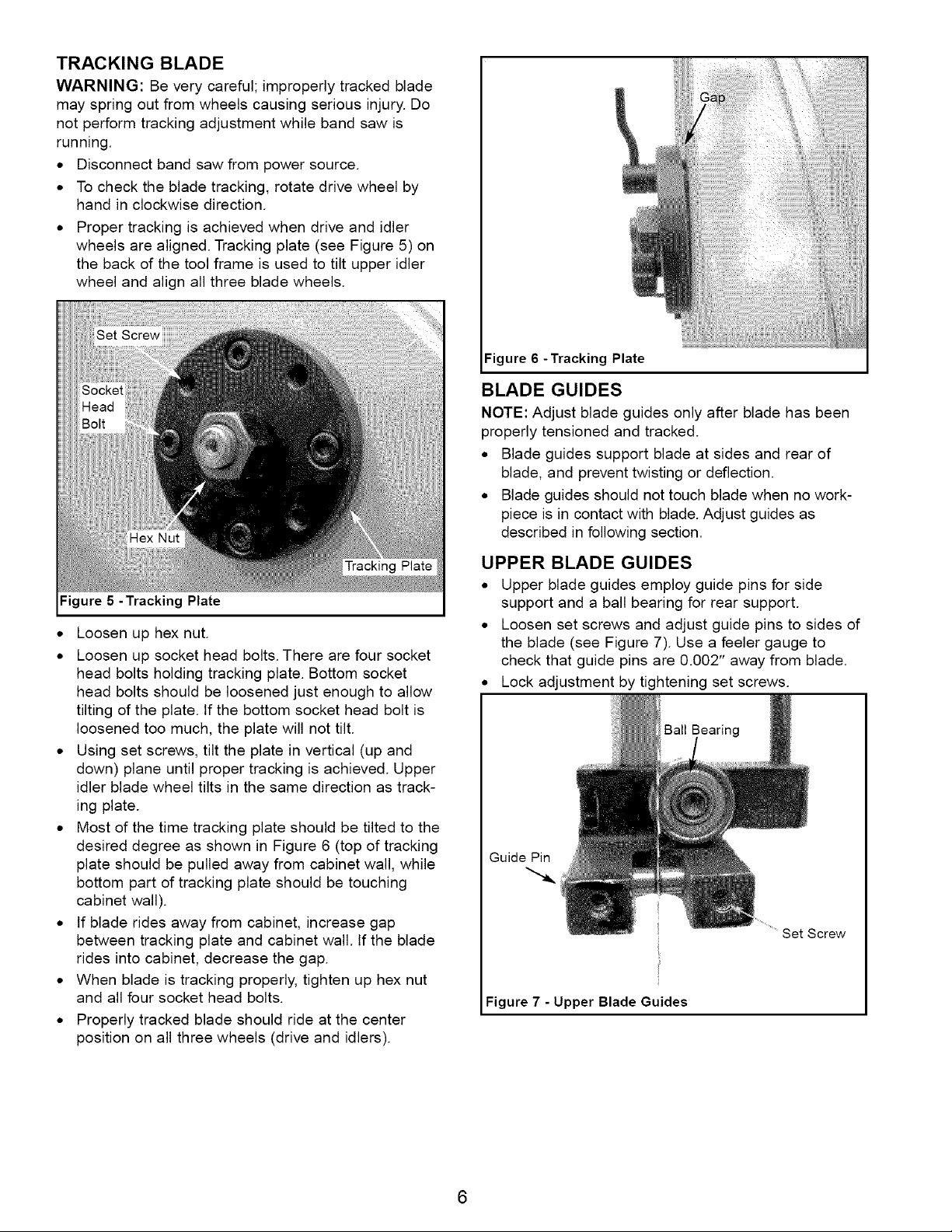
• Most of the time tracking plate should be tilted to the
desired degree as shown in Figure 6 (top of tracking
plate should be pulled away from cabinet wall, while
bottom part of tracking plate should be touching
cabinet wall).
• If blade rides away from cabinet, increase gap
between tracking plate and cabinet wall. If the blade
rides into cabinet, decrease the gap.
• When blade is tracking properly, tighten up hex nut
and all four socket head bolts.
• Properly tracked blade should ride at the center
position on all three wheels (drive and idlers).
:igure 6 -Tracking Plate
BLADE GUIDES
NOTE: Adjust blade guides only after blade has been
properly tensioned and tracked.
• Blade guides support blade at sides and rear of
blade, and prevent twisting or deflection.
• Blade guides should not touch blade when no work-
piece is in contact with blade. Adjust guides as
described in following section.
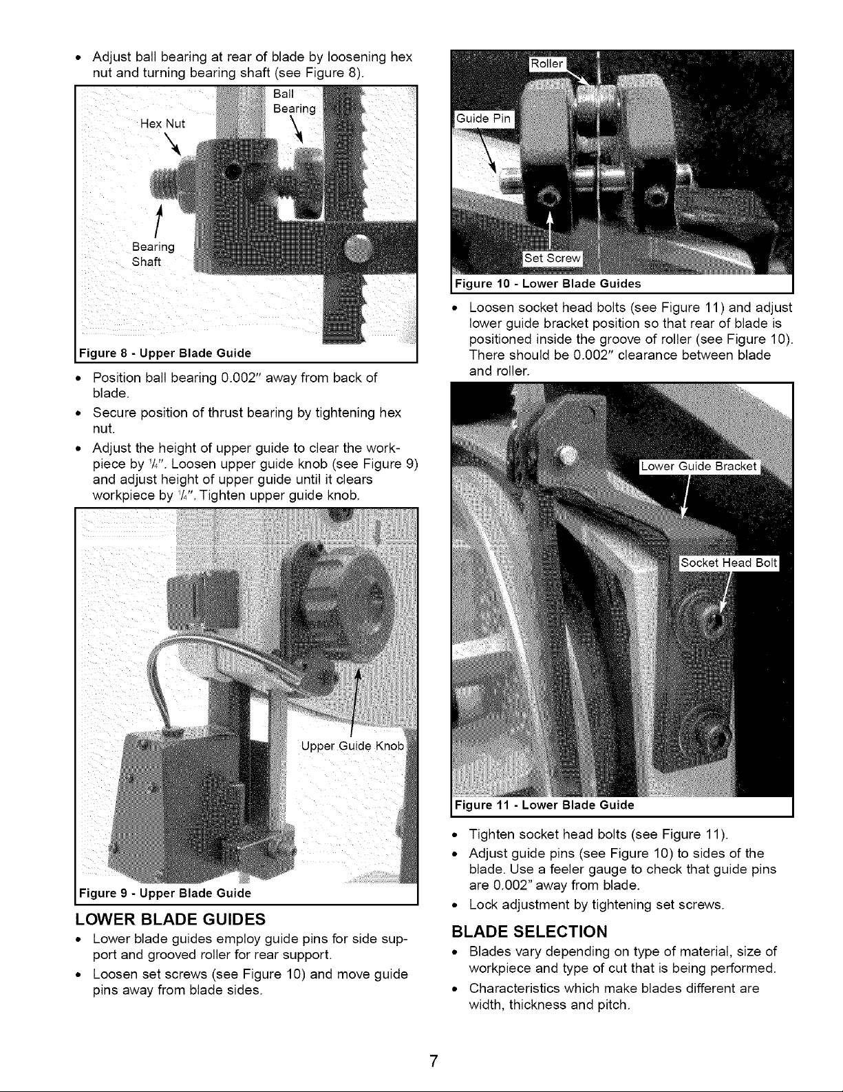
UPPER BLADE GUIDES
• Upper blade guides employ guide pins for side
support and a ball bearing for rear support.
• Loosen set screws and adjust guide pins to sides of
the blade (see Figure 7). Use a feeler gauge to
check that guide pins are 0.002" away from blade.
• Lock adjustment by tightening set screws.
Ball Bearing
Guide Pin
Set Screw
Figure 7 - Upper Blade Guides
6
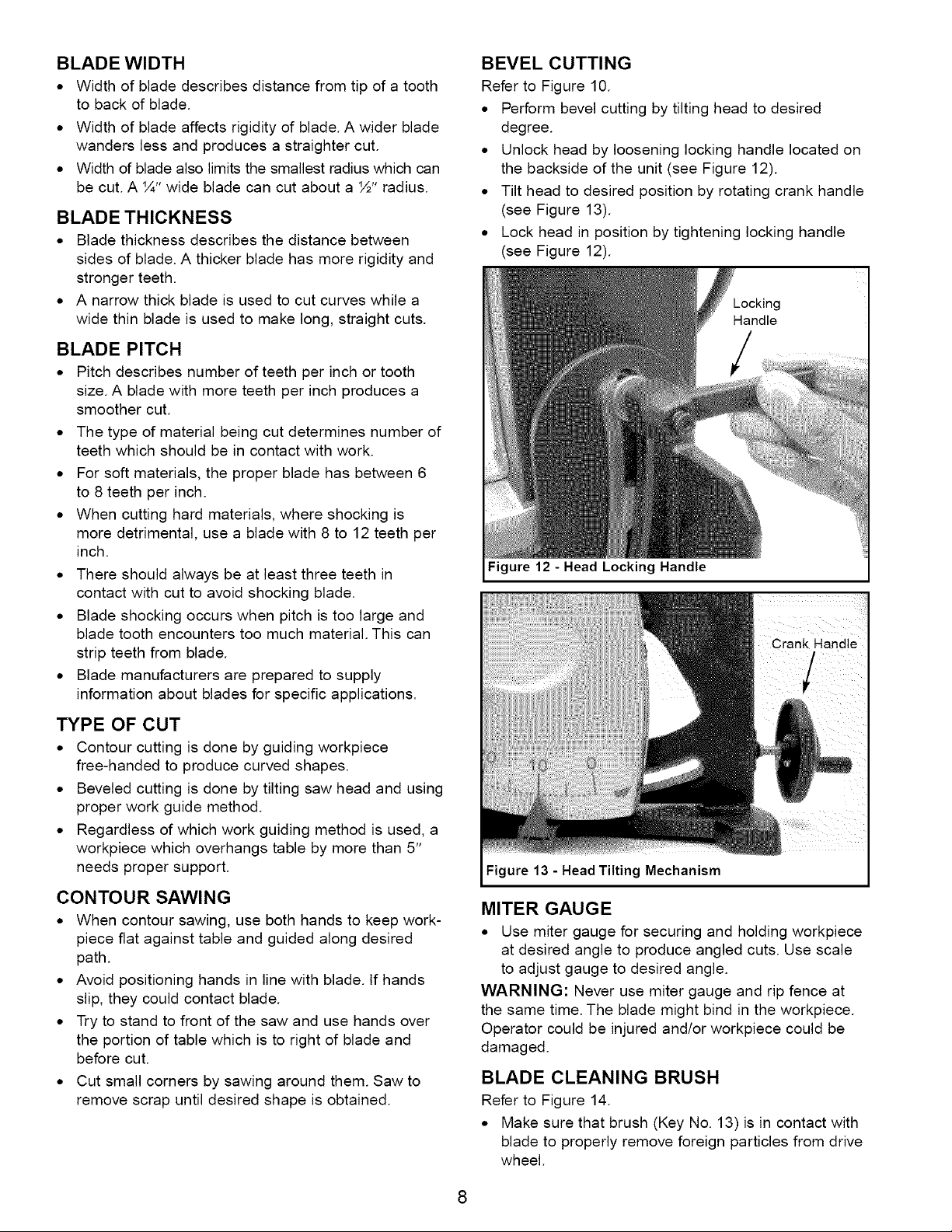
• Adjust ball bearing at rear of blade by loosening hex
nut and turning bearing shaft (see Figure 8).
Ball
Hex Nut
l
Bearing
Shaft
Figure 8 - Upper Blade Guide
• Position ball bearing 0.002" away from back of
blade.
• Secure position of thrust bearing by tightening hex
nut.
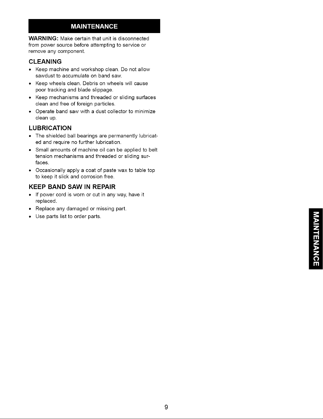
• Adjust the height of upper guide to clear the work-
piece by '/4". Loosen upper guide knob (see Figure 9)
and adjust height of upper guide until it clears
workpiece by V4".Tighten upper guide knob.
Figure 10 - Lower Blade Guides
• Loosen socket head bolts (see Figure 11) and adjust
lower guide bracket position so that rear of blade is
positioned inside the groove of roller (see Figure 10).
There should be 0.002" clearance between blade
and roller.
Figure 9 - Upper Blade Guide
LOWER BLADE GUIDES
• Lower blade guides employ guide pins for side sup-
port and grooved roller for rear support.
• Loosen set screws (see Figure 10) and move guide
pins away from blade sides.
Figure 11 - Lower Blade Guide
• Tighten socket head bolts (see Figure 11).
• Adjust guide pins (see Figure 10) to sides of the
blade. Use a feeler gauge to check that guide pins
are 0.002" away from blade.
• Lock adjustment by tightening set screws.
BLADE SELECTION
• Blades vary depending on type of material, size of
workpiece and type of cut that is being performed.
• Characteristics which make blades different are
width, thickness and pitch.
BLADE WIDTH
• Width of blade describes distance from tip of a tooth
to back of blade.
• Width of blade affects rigidity of blade. A wider blade
wanders less and produces a straighter cut.
• Width of blade also limits the smallest radius which can
be cut. A IA" wide blade can cut about a ½" radius.
BLADE THICKNESS
• Blade thickness describes the distance between
sides of blade. A thicker blade has more rigidity and
stronger teeth.
• A narrow thick blade is used to cut curves while a
wide thin blade is used to make long, straight cuts.
BLADE PITCH
• Pitch describes number of teeth per inch or tooth
size. A blade with more teeth per inch produces a
smoother cut.
• The type of material being cut determines number of
teeth which should be in contact with work.
• For soft materials, the proper blade has between 6
to 8 teeth per inch.
• When cutting hard materials, where shocking is
more detrimental, use a blade with 8 to 12 teeth per
inch.
• There should always be at least three teeth in
contact with cut to avoid shocking blade.
• Blade shocking occurs when pitch is too large and
blade tooth encounters too much material. This can
strip teeth from blade.
• Blade manufacturers are prepared to supply
information about blades for specific applications.
BEVEL CUTTING
Refer to Figure 10.
• Perform bevel cutting by tilting head to desired
degree.
• Unlock head by loosening locking handle located on
the backside of the unit (see Figure 12).
• Tilt head to desired position by rotating crank handle
(see Figure 13).
• Lock head in position by tightening locking handle
(see Figure 12).
Figure 12 - Head Locking Handle
TYPE OF CUT
• Contour cutting is done by guiding workpiece
free-handed to produce curved shapes.
• Beveled cutting is done by tilting saw head and using
proper work guide method.
• Regardless of which work guiding method is used, a
workpiece which overhangs table by more than 5"
needs proper support.
CONTOUR SAWING
• When contour sawing, use both hands to keep work-
piece flat against table and guided along desired
path.
• Avoid positioning hands in line with blade. If hands
slip, they could contact blade.
• Try to stand to front of the saw and use hands over
the portion of table which is to right of blade and
before cut.
• Cut small corners by sawing around them. Saw to
remove scrap until desired shape is obtained.
Figure 13 -Head Tilting Mechanism
MITER GAUGE
• Use miter gauge for securing and holding workpiece
at desired angle to produce angled cuts. Use scale
to adjust gauge to desired angle.
WARNING: Never use miter gauge and rip fence at
the same time. The blade might bind in the workpiece.
Operator could be injured and/or workpiece could be
damaged.
BLADE CLEANING BRUSH
Refer to Figure 14.
• Make sure that brush (Key No. 13) is in contact with
blade to properly remove foreign particles from drive
wheel.
8
WARNING: Make certain that unit is disconnected
from power source before attempting to service or
remove any component.
CLEANING
• Keep machine and workshop clean. Do not allow
sawdust to accumulate on band saw.
• Keep wheels clean. Debris on wheels will cause
poor tracking and blade slippage.
• Keep mechanisms and threaded or sliding surfaces
clean and free of foreign particles.
• Operate band saw with a dust collector to minimize
clean up.
LUBRICATION
• The shielded ball bearings are permanently lubricat-
ed and require no further lubrication.
• Small amounts of machine oil can be applied to belt
tension mechanisms and threaded or sliding sur-
faces.
• Occasionally apply a coat of paste wax to table top
to keep it slick and corrosion free.
KEEP BAND SAW IN REPAIR
• If power cord is worn or cut in any way, have it
replaced.
• Replace any damaged or missing part.
• Use parts list to order parts.
 Loading...