

Craftsman 351214140 Owner’s Manual

Operator's Manual
BAND SAW WITH STAND
Model No.
351.214140
CAUTION: Read and follow
all Safety Rules and Operating
Instructions before First Use
of this Product.
Sears, Roebuck and Co., Hoffman Estates, IL 60179 U.S.A.
www.sears.com/craftsman
25923.00 Draft (12/19/07)
Warranty.................................... 2
SafetyRules............................... 2-3
Unpacking.................................. 3
Assembly................................. 3-4
Installation................................. 4-5
Operation................................ 5-10
Maintenance............................. 10-11
Troubleshooting........................... 12-13
PartsIllustrationsandLists.................. 14-17
ONE-YEAR FULL WARRANTY ON
CRAFTSMAN TOOL
If this Craftsman tool fails due to a defect in material or
workmanship within one year from the date of purchase,
call 1-800-4-MY-HOME® TO ARRANGE FOR FREE
REPAIR (or replacement if repair proves impossible).
If this tool is used for commercial or rental purposes, this
warranty will apply for only 90 days from the date of
purchase.
This warranty applies only while this tool is in the
United States.
This warranty gives you specific legal rights and you may
also have other rights which vary from state to state.
Sears, Roebuck and Co., Hoffman Estates, IL 60179
WARNING: For your own safety, read all of the
instructions and precautions before operating tool.
CAUTION: Always follow proper operating procedures
as defined in this manual -- even if you are familiar
with use of this or similar tools. Remember that being
careless for even a fraction of a second can result in
severe personal injury.
BE PREPARED FOR JOB
• Wear proper apparel. Do not wear loose clothing,
gloves, neckties, rings, bracelets or other jewelry
which may get caught in moving parts of machine.
• Wear protective hair covering to contain long hair.
• Wear safety shoes with non-slip soles.
• Wear safety glasses complying with United States
ANSI Z87.1. Everyday glasses have only impact
resistant lenses. They are NOT safety glasses.
• Wear face mask or dust mask if operation is dusty.
• Be alert and think clearly. Never operate power tools
when tired, intoxicated or when taking medications
that cause drowsiness.
PREPARE WORK AREA FOR JOB
• Keep work area clean. Cluttered work areas invite
accidents.
• Do not use power tools in dangerous environments.
Do not use power tools in damp or wet locations. Do
not expose power tools to rain.
• Work area should be properly lighted.
• Proper electrical receptacle should be available for
tool. Three-prong plug should be plugged directly
into properly grounded, three-prong receptacle.
• Extension cords should have a grounding prong and
the three wires of the extension cord should be of
the correct gauge.
• Keep visitors at a safe distance from work area.
• Keep children out of workplace. Make workshop
childproof. Use padlocks, master switches or remove
switch keys to prevent any unintentional use of
power tools.
TOOL SHOULD BE MAINTAINED
• Always unplug tool prior to inspection.
• Consult manual for specific maintaining and
adjusting procedures.
• Keep tool lubricated and clean for safest operation.
• Remove adjusting tools. Form habit of checking to
see that adjusting tools are removed before switch-
ing machine on.
• Keep all parts in working order. Check to determine
that the guard or other parts will operate properly
and perform their intended function.
• Check for damaged parts. Check for alignment of
moving parts, binding, breakage, mounting and any
other condition that may affect a tool's operation.
• A guard or other part that is damaged should be
properly repaired or replaced. Do not perform
makeshift repairs. (Use parts list provided to order
replacement parts.)
KNOW HOW TO USE TOOL
• Use right tool for job. Do not force tool or attachment
to do a job for which it was not designed.
• Disconnect tool when changing blade.
• Avoid accidental start-up. Make sure that the tool is
in the "off" position before plugging in.
• Do not force tool. It will work most efficiently at the
rate for which it was designed.
• Keep hands away from moving parts and cutting
surfaces.
• Never leave tool running unattended. Turn the power
off and do not leave tool until it comes to a complete
stop.
• Do not overreach. Keep proper footing and balance.
• Never stand on tool. Serious injury could occur if tool
is tipped or if blade is unintentionally contacted.
• Know your tool. Learn the tool's operation, applica-
tion and specific limitations.
• Use recommended accessories (refer to page 17).
Use of improper accessories may cause risk of
injury to persons.
© Sears, Roebuck and Co. 2
. Handle workpiece correctly. Protect hands from pos-
sible injury.
° Turn machine off if it jams. Blade jams when it digs
too deeply into workpiece. (Motor force keeps it
stuck in the work.) Do not remove jammed or cut off
pieces until the saw is turned off, unplugged and the
blade has stopped.
WARNING: The operation of any power tool can result
in foreign objects being thrown into the eyes, which can
result in severe eye damage.
Always wear safety goggles complying with United
States ANSI Z87.1 (shown on package) before com-
mencing power tool operation. Safety goggles are avail-
able through your Sears catalog.
Check for shipping damage. If damage has occurred, a
claim must be filed with carrier. Check for complete-
ness. Immediately report missing parts to dealer.
The band saw comes assembled as one unit. Additional
parts which need to be fastened to the saw should be
located and accounted for before assembling (see
Figure 1).
A Pulleys Cover Assembly (1)
B Vertical Table (1)
C Vertical Table Reinforcing Bracket (1)
D Workstop Assembly (1)
E Crank Handle Assembly (1)
Parts bag includes: #10-24 x _" pan head screw,
#10-24 hex nut, two ¼-20 x ½" hex head bolts, two
¼" flat washers, ¼"-20 x _" flat head screw and ¼"-20
hex nut.
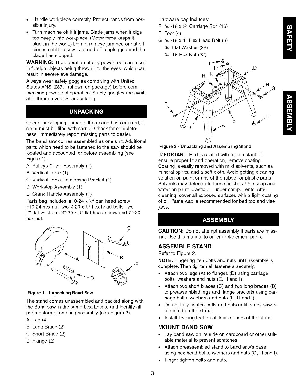
Hardware bag includes:
E _J'-18 x ½"Carriage Bolt (16)
F Foot (4)
G _6"-18 x 1" Hex Head Bolt (6)
H _6" Flat Washer (28)
I _J'-18 Hex Nut (22)
H
I HJ_" _ "/D
Figure 2 - Unpacking and Assembling Stand
IMPORTANT: Bed is coated with a protectant. To
ensure proper fit and operation, remove coating.
Coating is easily removed with mild solvents, such as
mineral spirits, and a soft cloth. Avoid getting cleaning
solution on paint or any of the rubber or plastic parts.
Solvents may deteriorate these finishes. Use soap and
water on paint, plastic or rubber components. After
cleaning, cover all exposed surfaces with a light coating
of oil. Paste wax is recommended for bed top and vise
jaws.
/
C
Figure 1 - Unpacking Band Saw
The stand comes unassembled and packed along with
the Band saw in the same box. Locate and identify all
parts before attempting assembly (see Figure 2).
A Leg (4)
B Long Brace (2)
C Short Brace (2)
D Flange (2)
CAUTION: Do not attempt assembly if parts are miss-
ing. Use this manual to order replacement parts.
ASSEMBLE STAND
Refer to Figure 2.
NOTE: Finger tighten bolts and nuts until assembly is
complete. Then tighten all fasteners securely.
. Attach two legs (A) to flanges (D) using carriage
bolts, washers and nuts (E, H and I).
. Attach two short braces (C) and two long braces (B)
to preassembled legs and flange brackets using car-
riage bolts, washers and nuts (E, H and I).
. Do not fully tighten bolts and nuts until bands saw is
mounted on the stand.
. Install leveling feet on all four corners of the stand.
MOUNT BAND SAW
° Lay band saw on its side on cardboard or other suit-
able material to prevent scratches
• Attach preassembled stand to band saw's base
using hex head bolts, washers and nuts (G, H and I).
• Finger tighten bolts and nuts.
3
. Carefully set the band saw and stand assembly
upright on the floor.
. Fully tighten all bolts and nuts.
. Adjust the leveling feet as necessary.
INSTALL CRANK HANDLE
• Line up set screw on crank handle with flat on the
lead screw shaft.
• Slide crank handle on the shaft and tighten set
screw.
INSTALL PULLEY COVER
Refer to Figure 16, page 16.
. Remove v-belt.
. Slide left side slot in the cover plate over transmis-
sion shaft.
. Lift up the motor and align its shaft with second slot
in the cover plate.
. Slide second slot in the pulley cover plate over motor
shaft.
. Install V-belt in proper pulleys combination for
desired blade speed. See Blade Speed Chart on
page 8.
o Tension V-belt by adjusting motor position and block-
ing it with thumb screw Key No. 42. Properly ten-
sioned V-belt should deflect about _" when applying
pressure with your thumb.
. Align mounting holes in the pulleys cover plate with
corresponding holes on the frame and secure it with
hex head bolts (Key No. 32) and washers (Key No.
31).
ATTACH WORK STOP ASSEMBLY
Refer to Figure 15, page 14.
• Insert end of work stop rod (Key No. 40) into bed
(Key No. 36). Secure position of rod with set screw
(Key No. 34).
• Slide work stop (Key No. 41) onto work stop rod and
secure with set screw (Key. No. 15).
• Adjust the work stop as described in Operation,
page 10.
ELECTRICAL CONNECTIONS
WARNING: Make sure unit is off and disconnected
from power source any time wiring is inspected.
POWER SOURCE
Band Saw is prewired for 115 volt, 60 HZ power source.
See figure 3 for wiring schematic.
The motor is designed for operation on the voltage and
frequency specified. Normal loads will be handled safe-
ly on voltages not more than 10% above or below the
specified voltage.
Running the unit on voltages which are not within the
range may cause overheating and motor burn-out.
Heavy loads require that the voltage at motor terminals
be no less than the voltage specified. Power supply to
the motor is controlled by a single pole toggle switch.
GROUNDING INSTRUCTIONS
WARNING: Improper connection of equipment
grounding conductor can result in the risk of electrical
shock. Equipment should be grounded while in use to
protect operator from electrical shock.
. Check with a qualified electrician if grounding
instructions are not understood or if in doubt as to
whether the tool is properly grounded.
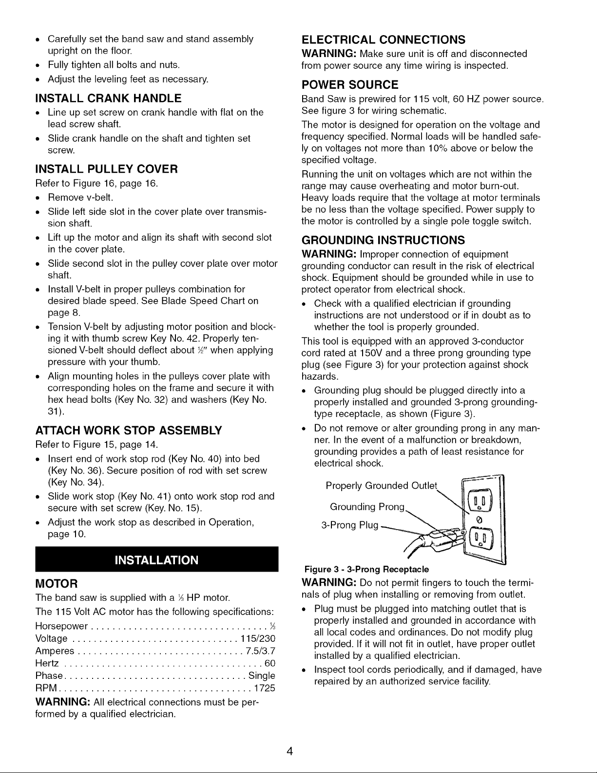
This tool is equipped with an approved 3-conductor
cord rated at 150V and a three prong grounding type
plug (see Figure 3) for your protection against shock
hazards.
. Grounding plug should be plugged directly into a
properly installed and grounded 3-prong grounding-
type receptacle, as shown (Figure 3).
. Do not remove or alter grounding prong in any man-
ner. In the event of a malfunction or breakdown,
grounding provides a path of least resistance for
electrical shock.
Properly Grounded Outlet
Grounding Prong,
3-Prong Plug
MOTOR
The band saw is supplied with a _ HP motor.
The 115 Volt AC motor has the following specifications:
Horsepower .................................
Voltage ............................... 115/230
Amperes ............................... 7.5/3.7
Hertz ..................................... 60
Phase .................................. Single
RPM .................................... 1725
WARNING: All electrical connections must be per-
formed by a qualified electrician.
Figure 3 - 3-Prong Receptacle
WARNING: Do not permit fingers to touch the termi-
nals of plug when installing or removing from outlet.
. Plug must be plugged into matching outlet that is
properly installed and grounded in accordance with
all local codes and ordinances. Do not modify plug
provided. If it will not fit in outlet, have proper outlet
installed by a qualified electrician.
. Inspect tool cords periodically, and if damaged, have
repaired by an authorized service facility.
4
• Green (or green and yellow) conductor in cord is the
grounding wire. If repair or replacement of the elec-
tric cord or plug is necessary, do not connect the
green (or green and yellow) wire to a live terminal.
Where a 2-prong wall receptacle is encountered, it
must be replaced with a properly grounded 3-prong
receptacle installed in accordance with National Electric
Code and local codes and ordinances.
WARNING: This work should be performed by a quali-
fied electrician.
A temporary 3-prong to 2-prong grounding adapter (see
Figure 4) is available for connecting plugs to a two pole
outlet if it is properly grounded.
Grounding Lug, _ Make Sure
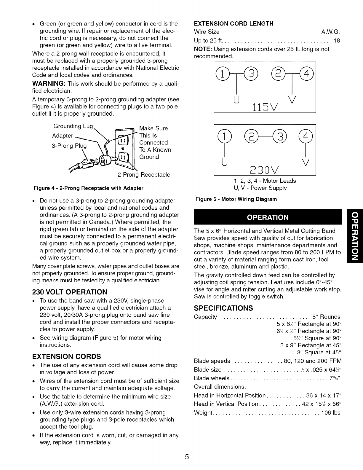
EXTENSION CORD LENGTH
Wire Size A.W.G.
Up to 25 ft.................................. 18
NOTE: Using extension cords over 25 ft. long is not
recommended.
U V
115V
3-Prong Connected
AdapteS_ This Is
2-Prong Receptacle
Figure 4 - 2-Prong Receptacle with Adapter
• Do not use a 3-prong to 2-prong grounding adapter
unless permitted by local and national codes and
ordinances. (A 3-prong to 2-prong grounding adapter
is not permitted in Canada.) Where permitted, the
rigid green tab or terminal on the side of the adapter
must be securely connected to a permanent electri-
cal ground such as a properly grounded water pipe,
a properly grounded outlet box or a properly ground-
ed wire system.
Many cover plate screws, water pipes and outlet boxes are
not properly grounded. To ensure proper ground, ground-
ing means must be tested by a qualified electrician.
To A Known
Ground
230 VOLT OPERATION
• To use the band saw with a 230V, single-phase
power supply, have a qualified electrician attach a
230 volt, 20/30A 3-prong plug onto band saw line
cord and install the proper connectors and recepta-
cles to power supply.
• See wiring diagram (Figure 5) for motor wiring
instructions.
EXTENSION CORDS
• The use of any extension cord will cause some drop
in voltage and loss of power.
• Wires of the extension cord must be of sufficient size
to carry the current and maintain adequate voltage.
• Use the table to determine the minimum wire size
(A.W.G.) extension cord.
• Use only 3-wire extension cords having 3-prong
grounding type plugs and 3-pole receptacles which
accept the tool plug.
• If the extension cord is worn, cut, or damaged in any
way, replace it immediately.
U V
B30V
1,2, 3, 4 - Motor Leads
U, V - Power Supply
Figure 5 - Motor Wiring Diagram
The 5 x 6" Horizontal and Vertical Metal Cutting Band
Saw provides speed with quality of cut for fabrication
shops, machine shops, maintenance departments and
contractors. Blade speed ranges from 80 to 200 FPM to
cut a variety of material ranging form cast iron, tool
steel, bronze, aluminum and plastic.
The gravity controlled down feed can be controlled by
adjusting coil spring tension. Features include 00-45°
vise for angle and miter cutting an adjustable work stop.
Saw is controlled by toggle switch.
SPECIFICATIONS
Capacity ............................ 5" Rounds
5 x 6_" Rectangle at 90°
6_ x _" Rectangle at 90°
5_" Square at 90°
3 x 9" Rectangle at 45°
3" Square at 45°
Blade speeds ................ 80, 120 and 200 FPM
Blade size ....................... 1/2x .025 x 64_"
Blade wheels .............................. 73/8"
Overall dimensions:
Head in Horizontal Position ............ 36 x 14 x 17"
Head in Vertical Position ............. 42 x 151/2x 56"
Weight ................................. 106 Ibs
5
SAFETY PRECAUTIONS
WARNING: Always observe the following safety pre-
cautions.
. Whenever adjusting or replacing any parts on the
band saw turn, switch off and remove plug from
power source.
. Make sure the stops are positioned and that the
automatic shut-off is operating.
. Check that the gear box has the proper amount of
lubricant.
. Make sure the blade guides are positioned correctly.
. Use the appropriate blade for the workpiece that is
being cut.
. Use a sharp blade. Replace dull blades or blades
which are missing teeth.
. Make sure the blade is tensioned properly and going
in the right direction.
. Use the proper blade speed for the work.
. For optimum performance, do not stall the motor or
reduce the speed. Use the proper feed pressure.
. Secure the workpiece in a stable position.
. Check that all guards are attached.
. After turning the switch on, let the blade come to full
speed. Then lower the blade onto the workpiece slowly.
. Keep hands away from the blade and all moving parts.
. Always wear eye protection or face shield.
HORIZONTAL STOP
Refer to Figure 15, page 14.
Horizontal stop bolt (Key No. 33) controls the position of
the head at the end of the cut. Head should contact the
horizontal stop when teeth are 1/8"below the surface of
the workbed.
HORIZONTAL STOP ADJUSTMENT
Refer to Figure 15, page 14.
• Place head in the horizontal position.
• Loosen the nuts (Key No. 35) on the horizontal stop
bolt. Adjust the horizontal stop bolt so that the teeth
are 1_,,below the surface of the workbed.
• Tighten the nuts to lock the position.
AUTOMATIC SHUTOFF
The switch is shut off when the blade passes through
the plane of the workbed. The switch should be shut off
as soon as the cut is finished.
IMPORTANT: Make sure the action of the switch is not
restricted by the horizontal stop.
LUBRICATION
Refer to Figure 16, page 16.
. All ball bearings are permanently lubricated and
should not require further lubrication.
. If the tracking wheel or head pivot is disassembled
for any reason, wipe off the old and reapply new
grease before assembly.
. The drive gears run in an oil bath and will not require
a lubricant change more often than once a year,
unless the lubricant is accidently contaminated or a
leak occurs because of improper replacement of the
gear box cover. During the first few days of opera-
tion, the worm gear drive will run hot. Unless the
temperature exceeds 200° F,there is no cause for
alarm.
. Under normal operation, gearbox oil should be
replaced once a year.
. The gearbox is designed to take 6 ounces of Mobil
630 gear oil.
. To replace gearbox oil:
1. Remove gearbox cover and drain old oil (there is
no oil plug)
2. Pour 6 ounces of fresh Mobil 630 gear oil in the
gearbox.
3. Install new gasket.
4. Install gearbox cover and fully tighten all bolts.
. The seal between the gearbox and the cover plate is
a gasket (Key No. 29). If cover plate is removed, the
surface should be cleaned and a new gasket should
be applied.
BLADE GUIDES
Band saw blade has to be twisted relative to the plane
in which it rotates. Blade must be properly positioned
relative to the workbed.
Blade guides hold the cutting portion of the blade in a
plane which is perpendicular to both the workbed and
the stationary vise and keep the blade in line with its
natural path around the blade wheels.
Inner guide bearings on the upper and lower guide assem-
blies keep the blade in line with the blade wheels. Outer
guide bearings keep the blade against the inner bearings.
Entire guide assembly is positioned at the factory to
produce the proper twist and should not need adjust-
ment, however, the position of blade guides should be
checked often.
NOTE: Since the blade position is related to both table
and the vise jaws, the relative position of the jaw to the
table is important. When assembled, the stationary jaw
must be perpendicular to the surface of the workbed.
CHECKING BLADE GUIDES
Refer to Figure 16, pages 16.
. Check that the blade teeth are perpendicular to the
machined surface of the base.
. Spread the blade guides as far apart as possible.
. Check that vise jaws are parallel and set for 90° cutoff.
. Position the vise jaws to have the maximum separa-
tion that will not interfere with the blade guides.
. With the head in horizontal position, use a square
against face of rear vise jaw and check that jaw is
90° to the side of blade.
. Check that the blade is in line with tracking and drive
wheels (Key Nos. 11 and 50).
. Raise the head.
6
 Loading...