

Craftsman 351211970 Owner’s Manual
Operator's Manual
®
MILL DRILL WITH
Model No.
351.211970
STAND
CAUTION: Read and follow
all Safety Rules and Operating
Instructions before First Use
of this Product.
Sears, Roebuck and Co., Hoffman Estates, IL 60179 U.S.A.
www.sears.com/craftsman
25140.00 Draft (02/19/07)
Warranty.................................... 2
SafetyRules............................... 2-3
Unpacking.................................. 3
Assembly................................. 3-4
Installation................................. 4-5
Operation................................. 6-7
Maintenance............................... 7-8
Troubleshooting.............................. 9
PartsIllustrationsandLists.................. 10-19
ONE-YEAR FULL WARRANTY ON
CRAFTSMAN PROFESSIONAL TOOL
If this Craftsman tool fails due to a defect in material or
workmanship within one year from the date of purchase,
call 1-800-4-MY-HOME® TO ARRANGE FOR FREE
REPAIR (or replacement if repair proves impossible).
This warranty does not include expendable parts, such
as lamps, batteries, bits or blades.
If this tool is ever used for commercial or rental purposes,
this warranty will apply for only 90 days from the date of
purchase.
This warranty gives you specific legal rights and you may
also have other rights which vary from state to state.
Sears, Roebuck and Co., Hoffman Estates, IL 60179
WARNING: For your own safety, read all of the
instructions and precautions before operating tool.
CAUTION: Always follow proper operating procedures
as defined in this manual -- even if you are familiar
with use of this or similar tools. Remember that being
careless for even a fraction of a second can result in
severe personal injury.
BE PREPARED FOR JOB
• Wear proper apparel. Do not wear loose clothing,
gloves, neckties, rings, bracelets or other jewelry
which may get caught in moving parts of machine.
• Wear protective hair covering to contain long hair.
• Wear safety shoes with non-slip soles.
• Wear safety glasses complying with United States
ANSI Z87.1. Everyday glasses have only impact
resistant lenses. They are NOT safety glasses.
• Wear face mask or dust mask if operation is dusty.
• Be alert and think clearly. Never operate power tools
when tired, intoxicated or when taking medications
that cause drowsiness.
PREPARE WORK AREA FOR JOB
• Keep work area clean. Cluttered work areas invite
accidents.
• Do not use power tools in dangerous environments.
Do not use power tools in damp or wet locations. Do
not expose power tools to rain.
• Work area should be properly lighted.
• Proper electrical receptacle should be available for
tool. Three-prong plug should be plugged directly
into properly grounded, three-prong receptacle.
• Extension cords should have a grounding prong and
the three wires of the extension cord should be of
the correct gauge.
• Keep visitors at a safe distance from work area.
• Keep children out of workplace. Make workshop
childproof. Use padlocks, master switches or remove
switch keys to prevent any unintentional use of
power tools.
TOOL SHOULD BE MAINTAINED
• Always unplug tool prior to inspection.
• Consult manual for specific maintaining and
adjusting procedures.
• Keep tool lubricated and clean for safest operation.
• Remove adjusting tools. Form habit of checking to
see that adjusting tools are removed before switch-
ing machine on.
• Keep all parts in working order. Check to determine
that the guard or other parts will operate properly
and perform their intended function.
• Check for damaged parts. Check for alignment of
moving parts, binding, breakage, mounting and any
other condition that may affect a tool's operation.
• A guard or other part that is damaged should be
properly repaired or replaced. Do not perform
makeshift repairs. (Use parts list provided to order
replacement parts.)
KNOW HOW TO USE TOOL
• Use right tool for job. Do not force tool or attachment
to do a job for which it was not designed.
• Disconnect tool when changing drill bit or cutter.
• Avoid accidental start-up. Make sure that the tool is
in the "off" position before plugging in.
• Do not force tool. It will work most efficiently at the
rate for which it was designed.
• Keep hands away from moving parts and cutting
surfaces.
• Never leave tool running unattended. Turn the power
off and do not leave tool until it comes to a complete
stop.
• Do not overreach. Keep proper footing and balance.
• Never stand on tool. Serious injury could occur if tool
is tipped or if drill bit or cutter is unintentionally
contacted.
2
• Know your tool. Learn the tool's operation, applica-
tion and specific limitations.
• Use recommended accessories (refer to page 15).
Use of improper accessories may cause risk of
injury to persons.
• Handle workpiece correctly. Protect hands from pos-
sible injury.
• Turn machine off if it jams. Drill bit or cutter jams
when it digs too deeply into workpiece. (Motor force
keeps it stuck in the work.) Do not remove workpiece
until the mill drill is turned off, unplugged and the
spindle has stopped.
• Clamp workpiece or brace against column to prevent
rotation.
• Feed work into a bit or cutter against the direction of
rotation of bit or cutter.
• Use recommended speed for mill drill accessory and
workpiece material.
CAUTION: Think safety! Safety is a combination of
operator common sense and alertness at all times
when tool is being used.
WARNING: The operation of any power tool can result in
foreign objects being thrown into the eyes, which can
result in severe eye damage. Always wear safety goggles
complying with United States ANSI Z87.1 (shown on
package) before commencing power tool operation.
Safety goggles are available through your Sears catalog.
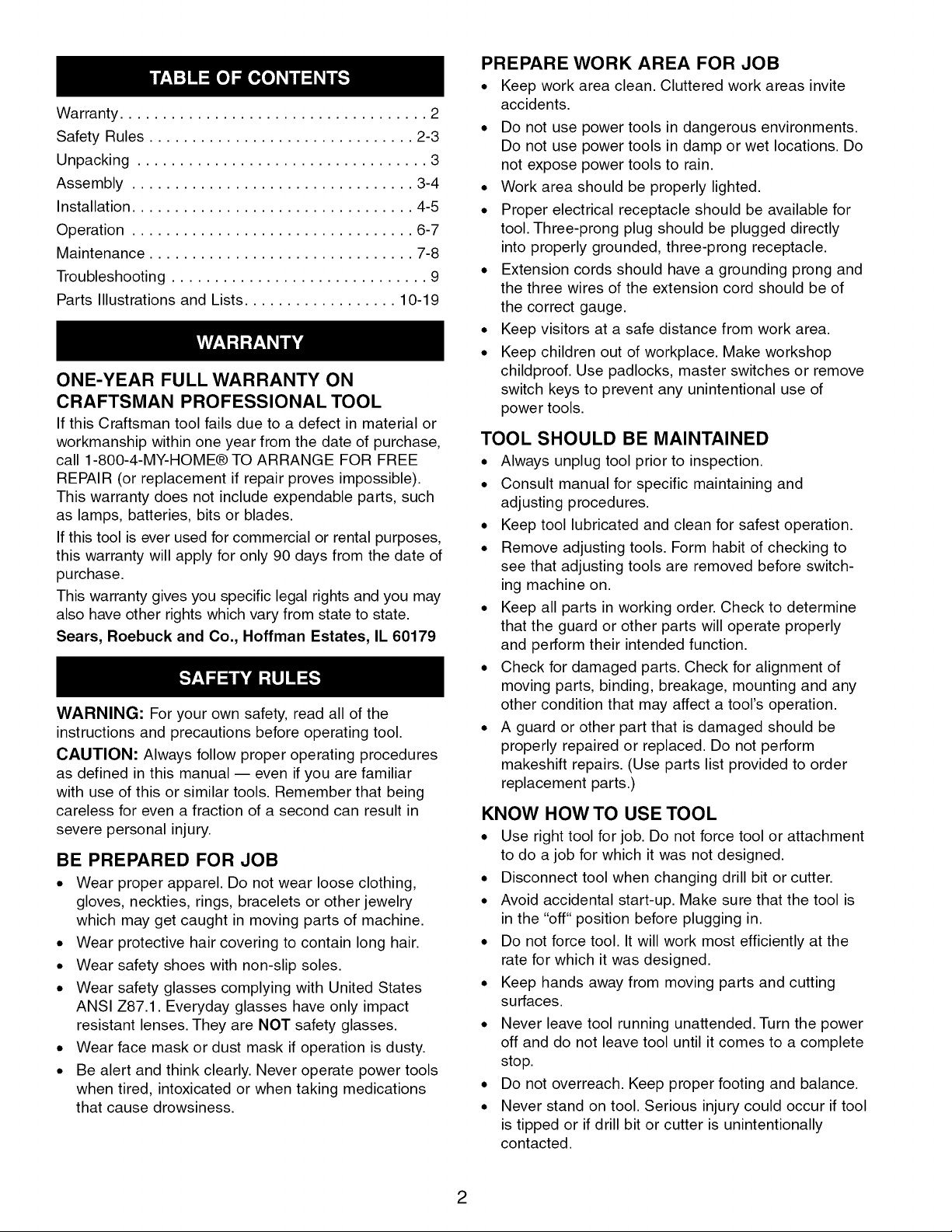
Refer to Figure 1.
Check for shipping damage. If damage has occurred, a
claim must be filed with carrier. Check for complete-
ness. Immediately report missing parts to dealer.
Carefully open crate and remove loose parts box.
Unbolt mill drill from shipping pallet and remove from
crate using heavy duty lifting equipment such as an
overhead crane.
WARNING: Be careful not to touch overhead power
lines, piping, lighting, etc. if lifting equipment is used.
Mill Drill weighs approximately 650 Ibs. Proper tools,
equipment and qualified personnel should be employed
in all phases of unpacking and installation.
Mill drill is shipped assembled except for certain parts
shipped loose in a wooden box. Locate and account for
the following parts:
A Drill chuck arbor
B %" Drill chuck with key
C Face mill arbor
D 3" Face milling cutter
E Three feed handwheels
F R8/MT3 Adapter
G Drawbar
Stand is shipped unassembled.
A
/
_ C D
/E F
Figure 1 - Unpacking
IMPORTANT: Table is coated with a protectant. To
ensure proper fit and operation, remove coating.
Coating is easily removed with mild solvents, such as
mineral spirits, and a soft cloth. Avoid getting solution
on paint or any of the rubber or plastic parts. Solvents
may deteriorate these finishes. Use soap and water on
paint, plastic or rubber components. After cleaning,
cover all exposed surfaces with a light coating of oil.
Paste wax is recommended for table top.
WARNING: Never use highly volatile solvents. Non
flammable solvents are recommended to avoid possible
fire hazard.
Refer to Figure 4, 7, 8, 9 and 11.
CAUTION: Do not attempt assembly if parts are miss-
ing. Use operator's manual to order replacement parts.
Mill drill must be mounted to a flat level surface. Use
shims or machine mounts if necessary. Do not mount
machine in direct sunlight. Heat caused by sunlight may
deform plastic parts on machine.
If stand is used, be sure to bolt mill drill to stand and
level stand to floor to minimize vibration. Use hex head
bolts, hex nuts and leveling pads (Figure 10, Key Nos.
8, 11 and 12) to align the mill drill. Tighten all nuts and
bolts that may have loosened in shipping. Secure mill
drill base to stand or bench.
ASSEMBLE STAND
Refer to Figure 11.
• Place both supports (Key No. 5) upside down on
floor.
• Attach feet (Key No. 9) and plate (Key No. 7) to each
support using hex head bolts, washers and hex nuts
(Key No. 2, 3 and 4). Finger tighten fasteners at this
time.
• Repeat on other side of supports with feet and plate
(Key No. 14).
• Turn unit right side up.
• Install left and right panels (Key Nos. 6 and 13).
Gently spread supports so that tabs on panels fit
into slots located on supports.
• Secure all fasteners from steps 2 and 3.
3
. Place chip pan (Key No. 1) on top of supports, locat-
ing the bottom rail of the chip pan inside the sup-
ports.
. Secure chip pan to supports using hex head bolts
and flat washers (Key Nos. 2 and 3).
MOUNT MILL DRILL TO STAND
Refer to Figure 11.
Place mill drill on stand with mounting holes aligned.
Bolt mill drill base to stand with four hex head bolts and
four flat washers (Key Nos. 3 and 10).
MOUNT TABLE HANDWHEELS
Refer to Figure 9.
Thread handles (Key No. 11) into feed handwheels (Key
No. 12). Secure handwheels to the ends of longitudinal
lead screw (Key No. 35) and cross lead screw (Key No.
20) using set screws (Key No. 30).
INSTALL DRAWBAR AND ARBOR
Refer to Figures 7 and 8.
Insert draw bar (Figure 8, Key No. 52) into top of spin-
dle. Be sure that arbor and spindle taper are clean of all
dirt, metal chips, oil, etc. Insert chuck or face mill arbor
(Figure 7, Key Nos. 52 and 55) into spindle and rotate
arbor to engage spindle key in arbor keyway. Push
arbor into spindle and thread draw bar into end of
arbor. Use a wrench to tighten draw bar securely.
Refer to Figures 3, 4 and 5.
MOTOR
The 115/230 Volt AC motor has the following
specifications:
Horsepower (Continuous Duty) ................. 1
Voltage ............................... 115/230
Amps ................................. 16.2/8.1
Hertz ..................................... 60
Phase .................................. Single
RPM .................................... 1725
POWER SOURCE
The motor is designed for operation on the voltage and
frequency specified. Normal loads will be handled safe-
ly on voltages not more than 10% above or below the
specified voltage.
Running the unit on voltages which are not within the
range may cause overheating and motor burn-out.
Heavy loads require that the voltage at motor terminals
be no less than the voltage specified.
GROUNDING INSTRUCTIONS
WARNING: Improper connection of equipment
grounding conductor can result in the risk of electrical
shock. Equipment should be grounded while in use to
protect operator from electrical shock.
Check with a qualified electrician if grounding instruc-
tions are not understood or if in doubt as to whether the
tool is properly grounded.
This tool is equipped with an approved 3 conductor
cord rated at 300V. A qualified electrician should wire
appropriate 3-prong plug to mill drill line cord.
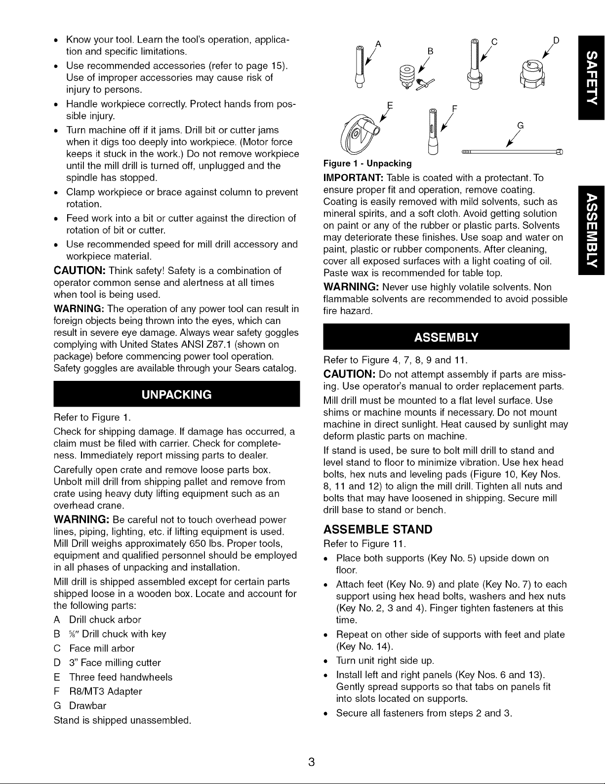
Grounding plug should be plugged directly into a prop-
erly installed and grounded 3-prong grounding-type
receptacle, as shown (Figure 2).
Properly Grounded Outlet --_;
Grounding Prong
3-Prong Plug II
Figure 2 - 3-Prong Receptacle
Do not remove or alter grounding prong in any manner.
In the event of a malfunction or breakdown, grounding
provides a path of least resistance for electrical shock.
WARNING: Do not permit fingers to touch the termi-
nals of plug when installing or removing from outlet.
Plug must be plugged into matching outlet that is prop-
erly installed and grounded in accordance with all local
codes and ordinances. Do not modify plug provided. If it
will not fit in outlet, have proper outlet installed by a
qualified electrician.
Inspect tool cords periodically, and if damaged, have
them repaired by an authorized service facility.
Green (or green and yellow) conductor in cord is the
grounding wire. If repair or replacement of the electric
cord or plug is necessary, do not connect the green (or
green and yellow) wire to a live terminal.
Where a 2-prong wall receptacle is encountered, it
must be replaced with a properly grounded 3-prong
receptacle installed in accordance with National Electric
Code and local codes and ordinances.
WARNING: This work should be performed by a quali-
fied electrician.
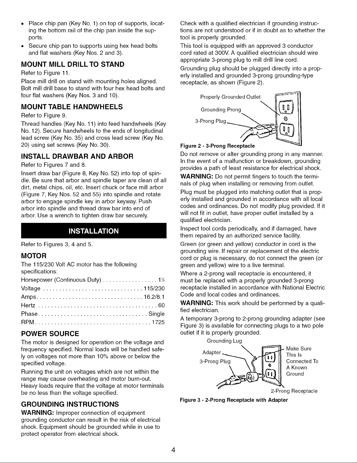
A temporary 3-prong to 2-prong grounding adapter (see
Figure 3) is available for connecting plugs to a two pole
outlet if it is properly grounded.
Grounding Lug
Adapter This Is
3-Prong ConnectedTo
__ Make Sure
Figure 3 - 2-Prong Receptacle with Adapter
A Known
Ground
2-Prong Receptacle
4
Do not use a 3-prong to 2-prong grounding adapter
unless permitted by local and national codes and ordi-
nances. (A 3-prong to 2-prong grounding adapter is not
permitted in Canada.) Where permitted, the rigid green
tab or terminal on the side of the adapter must be
securely connected to a permanent electrical ground
such as a properly grounded water pipe, a properly
grounded outlet box or a properly grounded wire system.
Many cover plate screws, water pipes and outlet boxes
are not properly grounded. To ensure proper ground,
grounding means must be tested by a qualified electrician.
EXTENSION CORDS
• The use of any extension cord will cause some drop
in voltage and loss of power.
• Wires of the extension cord must be of sufficient size
to carry the current and maintain adequate voltage.
• Use the table to determine the minimum wire size
(A.W.G.) extension cord.
• Use only 3-wire extension cords having 3-prong
grounding type plugs and 3-pole receptacles which
accept the tool plug.
• If the extension cord is worn, cut or damaged in any
way, replace it immediately.
EXTENSION CORD LENGTH
Wire Size A.W.G.
Up to 50 ft. (115 volts) ........................ 12
Up to 50 ft. (230 volts) ........................ 16
NOTE: Using extension cords over 50 ft. long is not
recommended.
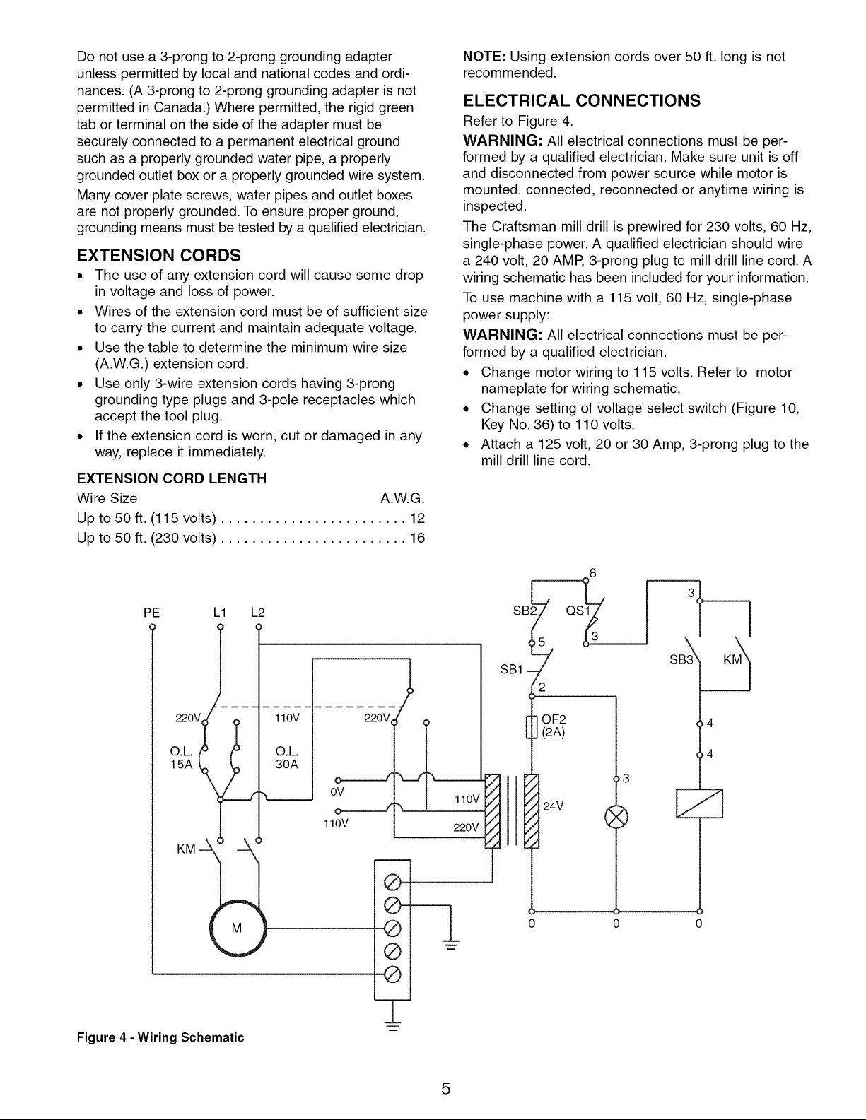
ELECTRICAL CONNECTIONS
Refer to Figure 4.
WARNING: All electrical connections must be per-
formed by a qualified electrician. Make sure unit is off
and disconnected from power source while motor is
mounted, connected, reconnected or anytime wiring is
inspected.
The Craftsman mill drill is prewired for 230 volts, 60 Hz,
single-phase power. A qualified electrician should wire
a 240 volt, 20 AMP, 3-prong plug to mill drill line cord. A
wiring schematic has been included for your information.
To use machine with a 115 volt, 60 Hz, single-phase
power supply:
WARNING: All electrical connections must be per-
formed by a qualified electrician.
• Change motor wiring to 115 volts. Refer to motor
nameplate for wiring schematic.
• Change setting of voltage select switch (Figure 10,
Key No. 36) to 110 volts.
• Attach a 125 volt, 20 or 30 Amp, 3-prong plug to the
mill drill line cord.
PE L1 L2
220y
O.L.
15A
110V
O.L.
30A
OV
1lOV
220V
®
@---
o q
®
®
220V
OF2
(2A)
0 0
]
4
4
E
Figure 4 - Wiring Schematic
_====_
5
Refer to Figures 5, 7, 8 and 9.
Craftsman 12-Speed Mill Drill Model 21197 is a rugged-
ly constructed machine providing accurate milling,
drilling and boring capabilities. The fully enclosed R-8
spindle has heavy-duty tapered thrust bearings at top
and bottom of quill, adjustable depth stop with scale,
fine feed adjustment handwheel with .001" graduations
and quill lock down handle for securely clamping spin-
dle at desired depth. One piece cast iron head rotates
360 ° and travels vertically by rack and pinion.
Hinged pulley cover allows fast and easy speed
changes. Large 31_ x 9¾" table has dovetail ways with
adjustable gibs and bronze lead screw nuts for accurate
and rigid table positioning. Table has four %" T-slots,
zero-setting handwheel dials with .001" graduations,
adjustable stops for longitudinal feed and cross feed
way cover.
A 1_/2HE 1725 RPM, 115/230 volt, 60 Hz single-phase
motor and 115v work lamp are included. Prewired for
230v.
Craftsman Mill Drill comes with a heavy-duty stand.
Stand is 14 gauge steel providing strength and rigidity.
Stand features mounting flanges for mounting stand to
floor, large chip pan, mounting bolts and leveling pads.
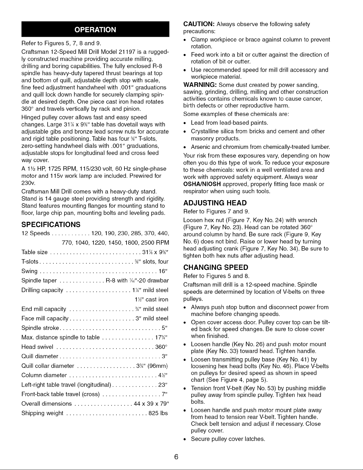
SPECIFICATIONS
12 Speeds ............ 120, 190, 230,285, 370, 440,
770, 1040, 1220, 1450, 1800, 2500 RPM
Table size ............................ 31_ x 9_"
T-slots ............................. %"slots, four
Swing .................................... 16"
Spindle taper .............. R-8 with W'-20 drawbar
Drilling capacity .................... 1¼" mild steel
1_" cast iron
End mill capacity .................... ¾" mild steel
Face mill capacity .................... 3" mild steel
Spindle stroke ............................... 5"
Max. distance spindle to table ................ 17_"
Head swivel .............................. 360°
Quill diameter ............................... 3"
Quill collar diameter .................. 3_" (96mm)
Column diameter ........................... 4_"
Left-right table travel (longitudinal) .............. 23"
Front-back table travel (cross) .................. 7"
Overall dimensions .................. 44 x 39 x 79"
Shipping weight ......................... 825 Ibs
CAUTION: Always observe the following safety
precautions:
• Clamp workpiece or brace against column to prevent
rotation.
• Feed work into a bit or cutter against the direction of
rotation of bit or cutter.
• Use recommended speed for mill drill accessory and
workpiece material.
WARNING: Some dust created by power sanding,
sawing, grinding, drilling, milling and other construction
activities contains chemicals known to cause cancer,
birth defects or other reproductive harm.
Some examples of these chemicals are:
• Lead from lead-based paints.
• Crystalline silica from bricks and cement and other
masonry products.
• Arsenic and chromium from chemically-treated lumber.
Your risk from these exposures vary, depending on how
often you do this type of work. To reduce your exposure
to these chemicals: work in a well ventilated area and
work with approved safety equipment. Always wear
OSHA/NIOSH approved, properly fitting face mask or
respirator when using such tools.
ADJUSTING HEAD
Refer to Figures 7 and 9.
Loosen hex nut (Figure 7, Key No. 24) with wrench
(Figure 7, Key No. 23). Head can be rotated 360 °
around column by hand. Be sure rack (Figure 9, Key
No. 6) does not bind. Raise or lower head by turning
head adjusting crank (Figure 7, Key No. 34). Be sure to
tighten both hex nuts after adjusting head.
CHANGING SPEED
Refer to Figures 5 and 8.
Craftsman mill drill is a 12-speed machine. Spindle
speeds are determined by location of V-belts on three
pulleys.
• Always push stop button and disconnect power from
machine before changing speeds.
• Open cover access door. Pulley cover top can be tilt-
ed back for speed changes. Be sure to close cover
when finished.
• Loosen handle (Key No. 26) and push motor mount
plate (Key No. 33) toward head. Tighten handle.
• Loosen transmitting pulley base (Key No. 41) by
loosening hex head bolts (Key No. 46). Place V-belts
on pulleys for desired speed as shown in speed
chart (See Figure 4, page 5).
• Tension front V-belt (Key No. 53) by pushing middle
pulley away from spindle pulley. Tighten hex head
bolts.
• Loosen handle and push motor mount plate away
from head to tension rear V-belt. Tighten handle.
Check belt tension and adjust if necessary. Close
pulley cover.
• Secure pulley cover latches.
6
 Loading...