

Craftsman 351211930 Owner’s Manual

Operator's Manual
CRRFTSMRN
aft
GRINDER WITH STAND
Model No.
351.211930
CAUTION: Read and follow
all Safety Rules and Operating
Instructions before First Use
of this Product.
Sears, Roebuck and Co., Hoffman Estates, IL 60179 U.S.A.
www ,sears.corn/craftsman
2527300 Draft (03/09/07)
Warranty .................................................... 2
Safety Rules ........................................ 2
Unpacking ............................................... 4
Assembly ................................................... 4
Installation .................................................. 4-5
Operation ................................................ 5-6
Maintenance .......................................... 6
Troubleshooting ............................................. 7
Parts lllustration and List ............................ 8-I I
Espaffoi .............................................................. 12-17
ONE-YEAR FULL WARRANTY ON
CRAFTSMAN PROFESSIONAL TOOL
If thisCraftsman toolfails due to a defect in material or
workmanshipwithinone year from the date of purchase,
call 1-800-4-MY-HOME® TO ARRANGE FOR FREE
REPAIR (or replacement if repairproves impossible).,
This warranty does not include expendable parts, such
as lamps, batteries or grinding and wire wheels
If this toot is ever used for commercial or rental purposes,
this warranty will apply for only 90 days from the date of
purchase..
This warranty gives you specific legal rights and you may
also have other rights which vary from state to state.
Sears, Roebuck and Co,, Hoffman Estates, IL 60179
WARNING: Some dust created by power sanding, sawing,
grinding, drilling and other construction activities contains
chemicals known to cause cancer, birth defects or other
reproductive harm
Some examples of these chemicals are:
- Lead from lead-based paints
,= Crystalline silica from bricks and cement and other
masonry products..
- Arsenic and chromium from chemically-treated lumber.
Your risk from these exposures vary, depending on how often
you do this type of work To reduce your exposure to these
chemicals: work in a well ventilated area and work with
approved safety equipment Always wear OSHNNIOSH
approved, properly fitting face mask or respirator when using
such tools
WARNING: For your own safety, read all of the instructions
and precautions before operating tool..
CAUTION: Always follow proper operating procedures as
defined in this manual even if you are familiar with use of this
or similar tools Remember that being careless for even a
fraction of a second can result in severe personal injury
BE PREPARED FOR JOB
• Wear proper apparel,, Do not wear loose clothing, gloves,
neckties, rings, bracelets or other jewelry which may get
caught in moving parts of machine
• Wear protective hair covering to contain long hair.
• Wear safety shoes with non-slip soles.
,, Wear safety glasses complying with United States ANSi
Z87..1. Everyday glasses have only impact resistant lenses
They are NOT safety glasses.
= Wear Face mask or dust mask if operation is dusty
• Be alert and think clearly Never operate power tools when
tired, intoxicated or when taking medications that cause
drowsiness..
PREPARE WORK AREA FOR JOB
,, Keep work area clean Cluttered work areas invite
accidents_
• Do not use power tools in dangerous environments.. Do not
use power tools in damp or wet locations Do not expose
power tools to rain..
• Work area should be properly lighted_
,, Proper electrical receptacle should be available for toot..
Three prong plug should be plugged directly into properly
grounded, three-prong receptacle.
• Extension cords should have a grounding prong and the three
wires of the extension cord should be of the correct gauge
• Keep visitors at a safe distance from work area..
- Keep children out of workplace. Make workshop childproof
Use padlocks, master switches or remove switch keys to
prevent any unintentional use of power tools.
TOOL SHOULD BE MAINTAINED
= Always unplug tool prior to inspecfion_
• Consult manual for specific maintaining and adjusting
procedures.r
- Keep tool lubricated and clean for safest operation..
,, Remove adjusting tools Form habit of checking to see that
adjusting tools are removed before switching machine on.
• Keep all parts in working order Check to determine that the
guard or other parts will operate properly and perform their
intended function.
• Check for damaged parts Check for alignment of moving
parts, binding, breakage, mounting and any other condition
that may affect a tool's operation
. A guard or other part that is damaged should be properly
repaired or replaced° Do not perform makeshift repairs.
(Use parts list provided to order replacement parts.)
KNOW HOW TO USE TOOL
. Use right tool for job. Do not force tool or attachment to do
a job for which it was not designed.
. Disconnect tool when changing grinding wheels..
• Avoid accidental start-up. Make sure that the tool is in the
"off" position before plugging in.
• Do not force tool. It wilt work most efficiently at the rate for
which it was designed
• Keep hands away from moving parts and grinding surfaces.
• Never leave tool running unattended Turn the power off
and do not leave tool until it comes to a complete stop.
• Do not overreach.. Keep proper footing and balance.
• Never stand on tool Serious injury could occur if tool is
tipped oVerr.
• Know your tool.. Learn the tool's operation, application and
specific limitations
© Sears, Roebuck and Co
2
o Use recommended accessories (refer to page 9). Use of
improper accessories may cause risk of injury to persons..
,, Do not overtighten wheel nut. Replace cracked wheel
immediately. Use only flanges supplied with the grinder
o Adjust distance between wheel and tool rest to maintain
'/,_" or less gap..
° Handle the workpiece correctly Whenever possible, use
tool rest to support workpiece during grinding operation.
Turn tool off if it jams=
,, Always use guards and eyeshields_
,, Clean grinding dust from beneath tool frequently.
CAUTION: Think safety] Safety is a combination of operator
common sense and alertness at all times when tool is being
used..
WARNING: Do not attempt to operate tool until it is com-
pletely assembled according to the instructions°
F
Refer to Figures 1, 2 and 3, pages 3 and 4.
Check for shipping damage., tf damage has occurred, a claim
must be filled with carrier. Check for completeness.
Immediately report missing parts to dealer
The grinder comes assembled as one uniL
Two extra wheels are included:
• 8" Grinding wheel 36 grit (course)
• 8" Grinding wheel 60 grit (medium)
Parts for stand and additional parts which need to be fas-
tened to grinder, should be located and accounted for before
assembling
To be certain the grinding wheels have not been damaged in
shipping, strike the edges slightly with a metal object.. A ring-
ing sound indfcates a good wheel, but a dull noise may signal
a fracture
WARNING: If you suspect a wheel of being fractured,
replace it immediately Fractured wheels may shatter, causing
serious injury
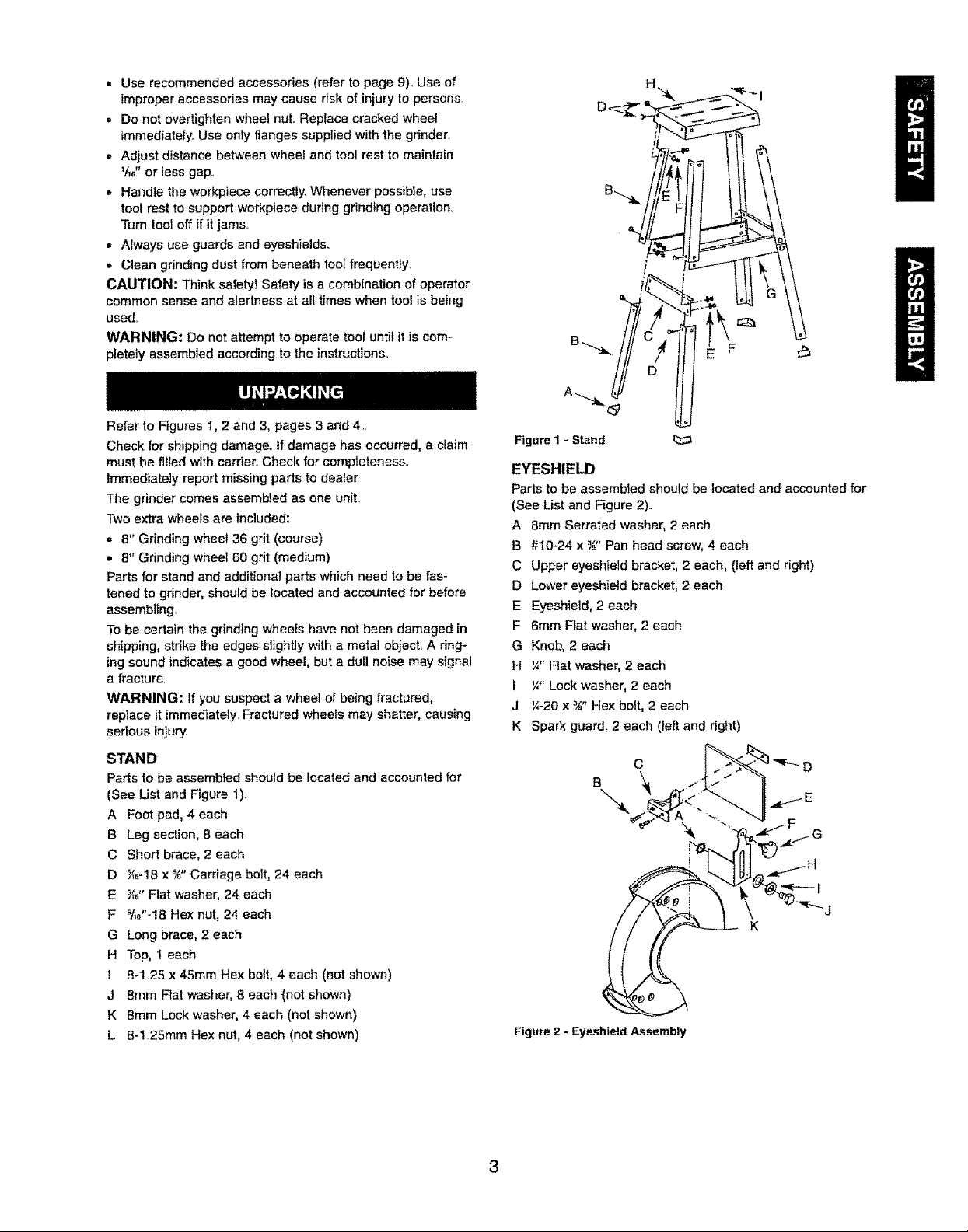
STAND
Parts to be assembled should be located and accounted for
(See List and Figure 1)
A Foot pad, 4 each
B Leg section, 8 each
C Short brace, 2 each
D _f_-18 x _" Carriage bolt, 24 each
E _,_" Flat washer, 24 each
F _/.,"=18 Hex nut, 24 each
G Long brace, 2 each
H Top, 1 each
1 8-1..25 x 45ram Hex bolt, 4 each (not shown)
J 8mm Flat washer, 8 each (not shown)
K 8ram Lock washer, 4 each (not shown)
L 8-1..25mm Hex nut, 4 each (not shown)
Figure1- Stand
EYESHIELD
Parts to be assembled should be located and accounted for
(See List and Figure 2).,
A 8ram Serrated washer, 2 each
B #I0-24 x ¾" Pan head screw, 4 each
C Upper eyeshie]d bracket, 2 each, (left and right)
D Lower eyeshield bracket, 2 each
E Eyeshield, 2 each
F 6mm Fiat washer, 2 each
G Knob, 2 each
H ¼" Flat washer, 2 each
I ¼" Lock washer, 2 each
J '/,-20 x ¾" Hex bolt, 2 each
K Spark guard, 2 each (left and right)
C D
B
'
Figure 2 - Eyeshleld Assembly
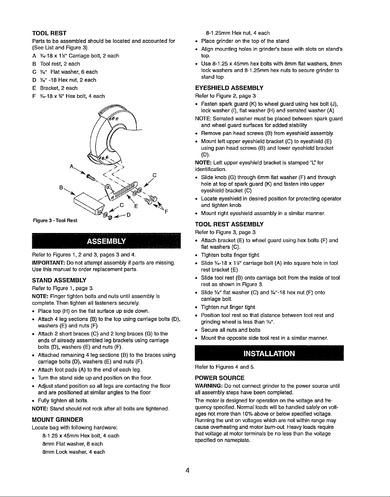
TOOLREST
Parts to be assembled should be located and accounted for
(See List and Figure 3).
A _;_18 x 1_" Carriage bolt, 2 each
B Tool rest, 2 each
C _" Fiat washer, 6 each
D _" -18 Hex nut, 2 each
E Bracket, 2 each
F _-18 x ¾" Hex bolt, 4 each
c
E
Figure 3 -Tool Rest
Refer to Figures 1, 2 and 3, pages 3 and 4.
IMPORTANT: Do not attempt assembly if parts are missing.
Use this manual to order replacement parts.
STAND ASSEMBLY
Refer to Figure 1, page 3.
NOTE: Finger tighten bolts and nuts until assembly is
complete. Then tighten all fasteners securely.
,, Place top (H) on the flat surface up side down..
,, Attach 4 leg sections (B) to the top using carriage bolts (D),
washers (E) and nuts (F).
,, Attach 2 short braces (C) and 2 long braces (G) to the
ends of already assembled leg brackets using carriage
bolts (D), washers (E) and nuts (F)
° Attached remaining 4 leg sections (B) to the braces using
carriage bolts (D), washers (E) and nuts (F)..
° Attach foot pads (A) to the end of each leg..
,, Turn the stand side up and position on the fioor..
= Adjust stand position so all legs are contacting the floor
and are positioned at similar angles to the floor
,, Fully tighten all bolts.
NOTE: Stand should not rock after all bolts are tightened°
MOUNT GRINDER
Locate bag with following hardware:
8-1.25 x 45mm Hex bolt, 4 each
8mm Flat washer, 8 each
8mm Lock washer, 4 each
8-1.25mm Hex nut, 4 each
, Place grinder on the top of the stand
,, Align mounting holes in grinder's base with siets on stand's
top.
,, Use 8-1..25 x 45mm hex bolts with 8mm flat washers, Bmm
lock washers and 8-1 ..25ram hex nuts to secure grinder to
stand top
EYESHIELD ASSEMBLY
Refer to Figure 2, page 3
,, Fasten spark guard (K) to wheel guard using hex bolt (J),
lock washer (i), flat washer (H) and serrated washer (A)
NOTE: Serrated washer must be placed between spark guard
and wheel guard surfaces for added stability
,, Remove pan head screws (B) from eyeshie]d assembly.
,, Mount left upper eyesh[eld bracket (C) to eyeshield (E)
using pan head screws (B) and lower eyeshield bracket
(U),,
NOTE: Left upper eyeshield bracket is stamped "C' for
identification.
° Slide knob (G) through 6mm fiat washer (F) and through
hole at top of spark guard (K) and fasten into upper
eyeshield bracket (C)
- Locate eyeshield in desired position for protecting operator
and tighten knob
- Mount right eyeshield assembly in a similar manner.
TOOL REST ASSEMBLY
Refer to Figure 3, page 3
° Attach bracket (E) to wheel guard using hex bolts (F) and
fiat washers (C)o
° Tighten bolts finger tight
° SIide _,1,-18x 1%" carriage bolt (A) into square hole in tool
rest bracket (E)
• Slide tool rest (B) onto carriage bolt from the inside of tool
rest as shown in Figure 3.
, Slide _" flat washer (C) and _I,"-18 hex nut (F) onto
carriage bolt..
• Tighten nut finger tight
• Position too_ rest so that distance between tool rest and
grinding wheel is tess than _,".
• Secure all nuts and bolts
- Mount the opposite side tool rest in a similar manner.
Refer to Figures 4 and 5.
POWER SOURCE
WARNING: Do not connect grinder to the power source until
all assembly steps have been completed,
The motor is designed for operation on the voltage and fre_
quency specified,, Normal loads will be handled safely on volt-
ages not more than 10% above or below specified voltage,
Running the unit on voltages which are not within range may
cause overheating and motor burn-out. Heavy loads require
that voltage at motor terminals be no tess than the voltage
specified on nameplate.
• Powersupplytothemotoriscontrolledbyasinglepole
lockingrockerswitchLRemovethekeytopreventunautho-
rizeduse,.
GROUNDING INSTRUCTIONS
WARNING: Improper connection of equipment grounding
conductor can result in the risk of electrical shock.. Equipment
should be grounded while in use to protect operator from
electrical shock
• Check with a qualified electrician if grounding instructions
are not understood or if in doubt as to whether the tool is
properly grounded
• This tool is equipped with an approved 3=conductor cord
rated at 300V and a 3-prong grounding type plug (Figure 2)
for your protection against shock hazards
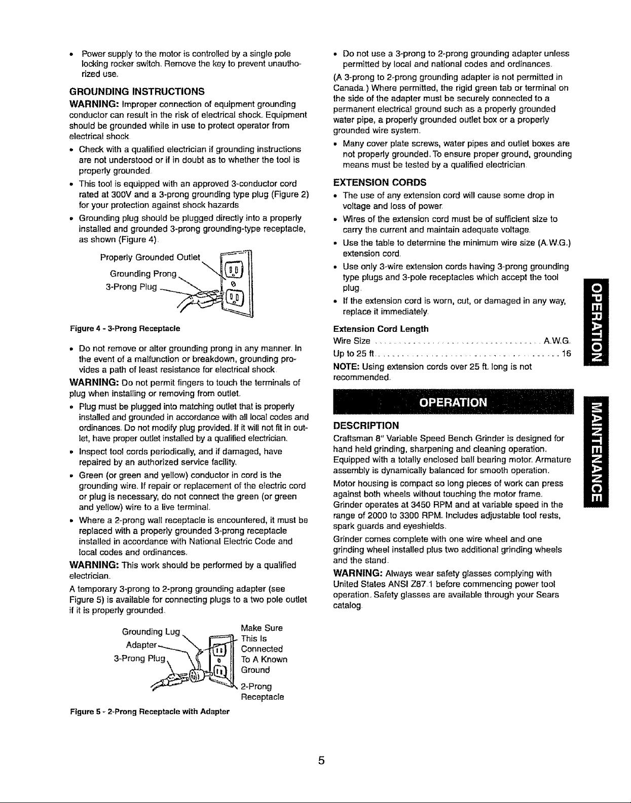
• Grounding plug should be plugged directly into a properly
installed and grounded 3-prong grounding-type receptacle,
as shown (Figure 4),
Prope dyG rounded Outiet =_...._Fr=..,_ __ _-.-n
Grounding Prong _,
3-Prong P}ug _.._.__
Figure 4 - 3-Prong Receptacle
• Do not remove or alter grounding prong in any manner, tn
the event of a maffunctton or breakdown, grounding pro-
vides a path of least resistance for electrical shock
WARNING: Do not permit fingers to touch the terminals of
plug when installing or removing from outlet.
,, Plug must be plugged into matching outlet that is propedy
installed and grounded in accordance with all local codes and
ordinances, Do not modify plug provided., ff it will not fit in out-
let, have proper outlet installed by a qualified electrician.
,, Inspect tool cords periodically, and if damaged, have
repaired by an authorized service facility..
• Green (or green and yellow) conductor in cord is the
grounding wire. If repair or replacement of the electric cord
or pSug is necessary, do not connect the green (or green
and yellow) wire to a live terminal,
,, Where a 2-prong wa_l receptacle is encountered, it must be
replaced with a properly grounded 3-prong receptacle
installed in accordance with National Electric Code and
local codes and ordinances..
WARNING: This work should be performed by a qualified
electrician.
A temporary 3-prong to 2-prong grounding adapter (see
Figure 5) is availabfe for connecting plugs to a two pole outlet
ff it is properly grounded.
Grounding Lug \
Adapter -_"_.._1
3 Prong P_. 1_
Figure 5 - 2-Prong Receptacle with Adapter
Make Sure
This Is
Connected
To A Known
Ground
2-Prong
Receptacle
• Do not use a 3-prong to 2-prong grounding adapter unless
permitted by local and national codes and ordinances.
(A 3-prong to 2-prong grounding adapter is not permitted in
Canada) Where permitted, the rigid green tab or terminal on
the side of the adapter must be securely connected to a
permanent electricat ground such as a properly grounded
water pipe, a properly grounded outtet box or a propedy
grounded wire system..
, Many cover plate screws, water pipes and outlet boxes are
not properly grounded, To ensure proper ground, grounding
means must be tested by a qualified electrician
EXTENSION CORDS
• The use of any extension cord wit!cause some drop in
voltage and lossof powe_
= Wires of the extension cord must be of sufficient size to
carry the currentand maintain adequate voltage,
• Use the table to determine the minimum wire size (A WG,.)
extension cord.
• Use only 3-wire extension cordshaving 3-prong grounding
type plugs and 3-pole receptacles which accept the tool
plug
• if the extensioncord is worn, cut, or damaged in any way,
replace it immediately,
Extension Cord Length
Wire Size ...................................... AW, G
Up to 25 ft .............................................................. 16
NOTE: Using extension cords ever 25 it, long is not
recommended.,
DESCRIPTION
Craftsman 8" Variable Speed Bench Grinder is designed for
hand heed grinding, sharpening and cleaning operetiom
Equipped with a totaliy enclosed ball beadng motor. Armature
assembly is dynamically balanced for smooth operation.
Motor housing is compact so long pieces of work can press
against both wheels without touching the motor frame..
Grinder operates at 3450 RPM and at variable speed in the
range of 2000 to 3300 RPMo includes adjustable tool rests,
spark guards and eyeshie[ds
Gdnder comes complete with one wire wheel and one
grinding wheel installed plus two additional grinding wheels
and the stand.
WARNING: Always wear safety glasses compfying with
United States ANSI Z87t before commencing power tool
operation. Safety glasses are available through your Sears
catalog
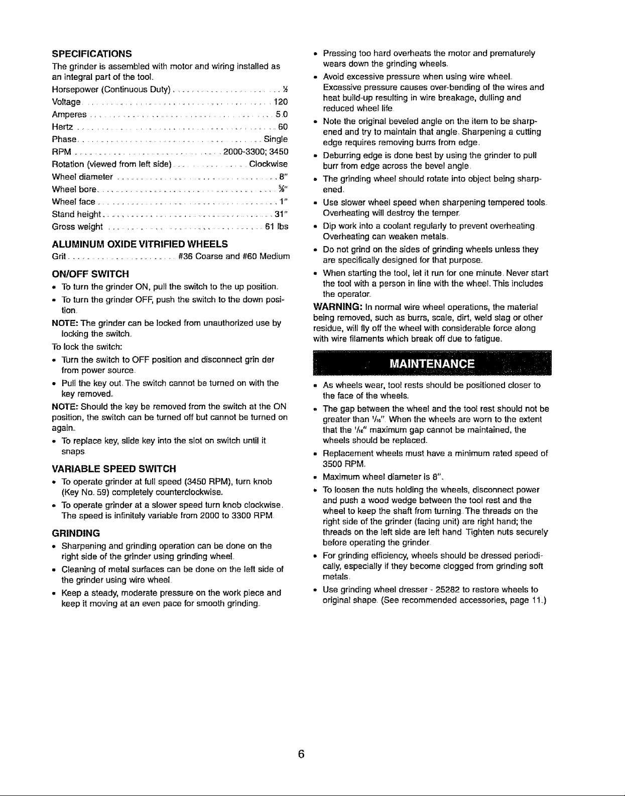
SPECIFICATIONS
The grinder is assembled with motor and wiring installed as
an integral part of the tool,.
Horsepower (Continuous Duty) .............................
Voltage ............................................................. 120
Amperes ..................................................... 5 O
Hertz ............................................. 60
Phase ................................................... Single
RPM .............................................. 2000-3300; 3450
Rotation (viewed from left side) ................. Clockwise
Wheel diameter ................................................... 8"
Wheel bore ............................................ s#,
Wheel face ................................................. 1"
Stand height .............................................. 31"
Gross weight ....................................... 61 lbs
ALUMINUM OXIDE VITRIFIED WHEELS
Grit .................................. #36 Coarse and _t60 Medium
ONIOFF SWITCH
,J To turn the grinder ON, pull the switch to the up position..
• To turn the grinder OFF, push the switch to the down posi-
tion
NOTE: The grinder can be locked from unauthorized use by
locking the switch_.
To lock the switch:
• Turn the switch to OFF position and disconnect grin der
from power source
• Pu!] the key out, The switch cannot be turned on with the
key removed,,
NOTE: Should the key be removed from the switch at the ON
position, the switch can be turned off but cannot be turned on
again,,
• To replace key, slide key into the slot on switch until it
snaps
VARIABLE SPEED SWITCH
° To operate grinder at full speed (3450 RPM), turn knob
(Key No., 59) completely counterclockwise.
° To operate grinder at a slower speed turn knob clockwise,
The speed is infinitely variable from 2000 to 3300 RPM
GRINDING
• Sharpening and grinding operation can be done on the
right side of the grinder using grinding wheel
• Cleaning of metal surfaces can be done on the left side of
the grinder using wire wheel
• Keep a steady, moderate pressure on the work piece and
keep it moving at an even pace for smooth gdnding.r
• Pressing too hard overheats the motor and prematurely
wears down the grinding wheels.
• Avoid excessive pressure when using wire wheel,,
Excessive pressure causes over-bending of the wires and
heat build-up resulting in wire breakage, dulling and
reduced wheel life
- Note the original beveled angle on the item to be sharp-
ened and try to maintain that angle, Sharpening a cutting
edge requires removing burrs from edge,
- Deburring edge is done best by using the grinder to pull
burr from edge across the bevel angle,
- The grinding wheel should rotate into object being sharp-
ened.
• Use slower wheel speed when sharpening tempered tools
Overheating wilt destroy the temper.
,, Dip work into a coolant regularly to prevent overheating
Overheating can weaken metals.
,, Do not grind on the sides of grinding wheels unless they
are specifically designed for that purpose.,
• When starting the tool, let it run for one minute, Never start
the toot with a person in line with the wheel This includes
the operator.
WARNING: In normal wire wheel operations, the material
being removed, such as burrs, scale, dirt, weld slag or other
residue, wilt fly off the wheel with considerable force along
with wire filaments which break off due to fatigue,
,, As wheels wear, toot rests should be positioned closer to
the face of the wheels.,
- The gap between the wheel and the tool rest should not be
greater than 't,," When the wheels are worn to the extent
that the V,_,"maximum gap cannot be maintained, the
wheels should be replaced.,
,, Replacement wheels must have a minimum rated speed of
3500 RPM
• Maximum wheel diameter is 8".
• To loosen the nuts holding the wheels, disconnect power
and push a wood wedge between the toot rest and the
wheel to keep the shaft from turning The threads on the
right side of the grinder (facing unit) are right hand; the
threads on the left side are left hand Tighten nuts securely
before operating the grinder
. For grinding efficiency, wheels should be dressed periodi-
cally, especially if they become clogged from gdnding soft
metals,
• Use grinding wheel dresser - 25282 to restore wheels to
original shape, (See recommended accessories, page I1.)
6
 Loading...