

Craftsman 32052751 Owner’s Manual
Operator's Manual
CRFIFTSMFIN°
C3 1/2" DRILL/DRIVER
Model No. 5275.1
• WARRANTY
®
LISTED
_WARNING: To reduce the risk of injury,
the user must read and understand the
Operator's Manual before using this product.
Sears Brands Management Corporation, Hoffman Estates,
IL 60179 U.S.A.
www.craftsman.com
• SAFETY
• DESCRIPTION
• ASSEMBLY
• OPERATION
• MAINTENANCE
• ESPANOL
i _-_:] ! _ [O_ [O']_O]_i / _ _i _'_
Warranty Page 2
Safety Symbols Pages 4-5
Safety Instructions Pages 6-8
Description Pages 9-10
Assembly Page 11
Operation Pages 12-18
Maintenance Pages 19-20
Troubleshooting Page 21
Parts List Pages 22-24
CRAFTSMAN LIMITED WARRANTY
FOR ONE YEAR from the date of sale, this product is warranted against any
defects in material or workmanship.
WITH PROOF OF SALE, a defective product will be replaced free of charge.
For warranty coverage details to obtain free replacement, visit the web
page: www.craftsman.com/warranty
This ONE YEAR warranty is void if this product is ever used while providing
commercial services or if rented to another person. For 90 DAY commercial
and rental use terms, see the Craftsman warranty web page.
This warranty gives you specific legal rights, and you may also have other
rights which vary from state to state.
Sears Brands Management Corporation, Hoffman Estates, IL 60179.
SAVE THESE INSTRUCTIONS!
READ ALL INSTRUCTIONS!
This drill/driver has many features for making its use more pleasant and
enjoyable. Safety, performance, and dependability have been given top priority
in the design of this product making it easy to maintain and operate.
2 © Sears Brands, LLC

DANGER: People with electronic devices, such as pacemakers, should
consult their physician(s) before using this product. Operation of electrical
equipment in close proximity to a heart pacemaker could cause interference or
failure of the pacemaker.
_WARNING: Some dust created by power sanding, sawing, grinding, drilling
and other construction activities contains chemicals known to the state of
California to cause cancer, birth defects or other reproductive harm. Some
examples of these chemicals are:
• Lead from lead-based paints
• Crystalline silica from bricks and cement and other masonry products, and
• Arsenic and chromium from chemically-treated lumber.
Your risk from these exposures varies, depending on how often you do this type
of work. To reduce your exposure to these chemical: work in a well ventilated
area, and work with approved safety equipment, such as those dust masks that
are specially designed to filter out microscopic particles.
_,'%1= q uk'i[,,,,_o_
The purpose of safety symbols is to attract your attention to possible dangers.
The safety symbols and the explanations with them deserve your careful
attention and understanding. The symbol warnings do not, by themselves,
eliminate any danger. The instructions and warnings they give are no substitutes
for proper accident prevention measures.
WARNING: Be sure to read and understand all safety instructions in this
manual, including all safety alert symbols such as "DANGER," "WARNING," and
"CAUTION" before using this tool. Failure to follow all instructions listed in this
manual may result in electric shock, fire, and/or serious personal injury.
SYMBOL SIGNAL MEANING
SAFETY ALERT SYMBOL: indicates DANGER, WARNING, or CAUTION; may
be used in conjunction with other symbols or pictographs.
DANGER: Indicates a hazardous situation which, if not avoided, will result in
death or serious injury.
WARNING: Indicates a hazardous situation which, if not avoided, could
result in death or serious injury.
CAUTION: Indicates a hazardous situation which, if not avoided, could
result in minor or moderate injury.
Damage prevention and Information Messages
These inform the user of important information and/or instructions that could
Beadto equipment or other property damage if they are not followed. Each
message is preceded by the word "NOTICE", as in the example below.
NOTICE: Equipment and/or property damage may result if these instructions are
not followed.
WARNING: To ensure safety and reliability, all repairs should be performed
by a qualified service technician.
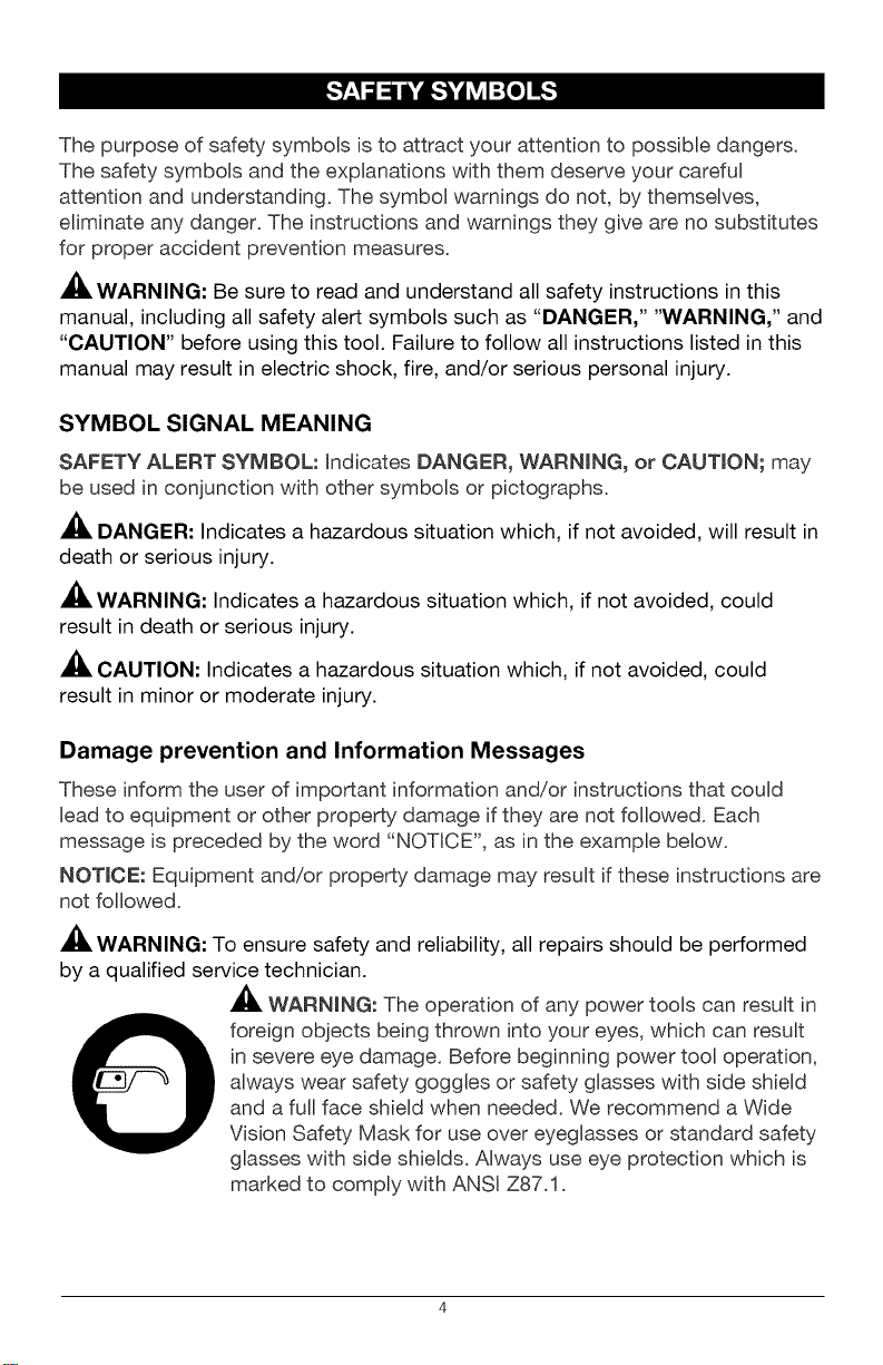
_, WARNmNG: The operation of any power tools can result in
foreign objects being thrown into your eyes, which can result
in severe eye damage. Before beginning power tool operation,
always wear safety goggles or safety glasses with side shield
and a full face shield when needed. We recommend a Wide
Vision Safety Mask for use over eyeglasses or standard safety
glasses with side shields. Always use eye protection which is
marked to comply with ANSI Z87.1.
SAVE THESE INSTRUCTIONS
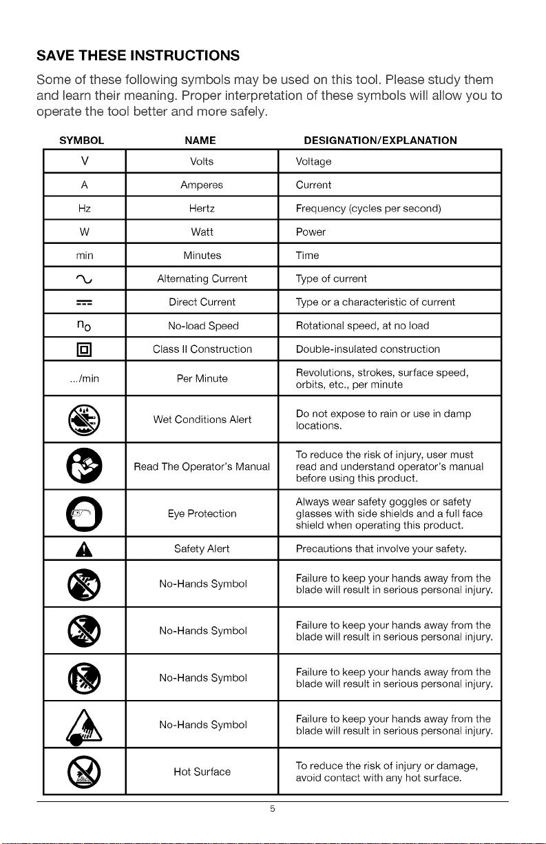
Some of these following symbols may be used on this tool. Please study them
and Beam their meaning. Proper interpretation of these symbols will allow you to
operate the tool better and more safely.
SYMBOL NAME DESIGNATION/EXPLANATION
V Volts Voltage
A Amperes Current
Hz Hertz Frequency (cycles per second)
W Watt Power
min Minutes Time
Alternating Current Type of current
---'== Direct Current Type or a characteristic of current
n o No-load Speed Rotational speed, at no load
[] Class II Construction Double-insulated construction
.../min Per Minute Revolutions, strokes, surface speed,
Wet Conditions Alert Do not expose to rain or use in damp
Read The Operator's Manual read and understand operator's manual
O Always wear safety goggles or safety
_, Alert Precautions that involve
Eye Protection glasses with side shields and a full face
Safety your safety.
No-Hands Symbol Failure to keep your hands away from theblade wil! result in serious personal injury.
No-Hands Failure to keep your hands away from the
No-Hands Failure to keep your hands away from the
No-Hands Symbol Failure to keep your hands away from the
Symbol
Symbol
orbits, etc., per minute
locations.
To reduce the risk of injury, user must
before using this product.
shield when operating this product.
blade wil! result in serious personal injury.
blade wil! result in serious personal injury.
blade wil! result in serious personal injury.
Hot Surface To reduce the risk of injury or damage,
avoid contact with any hot surface.
5
GENERAL POWER TOOL SAFETY WARNINGS
WARNING: Read all safety warnings and instructions. Failureto follow the
warnings and instructions may result in electric shock, fire and/or serious injury.
Save all warnings and instructions for future reference.
The term "power tool" inthe warnings refers to your mains=operated (corded)
power tool or battery=operated (cordless) power tool.
WORK AREA SAFETY
• Keep work area clean and well lit. Cluttered or dark areas invite accidents.
• Do not operate power tools in explosive atmospheres, such as in the
presence of flammable liquids, gases or dust. Power tools create sparks
which may ignite the dust or fumes.
• Keep children and bystanders away while operating a power tool.
Distractions can cause you to lose control.
ELECTRICAL SAFETY
• Power tool plugs must match the outlet. Never modify the plug in any
way. Do not use any adaptor plugswith earthed (grounded) power tools.
Unmodified plugs and matching outlets will reduce risk of electric shock
• Avoid body contact with earthed or grounded surfaces such as pipes,
radiators, ranges and refrigerators. There is an increasedrisk of electric
shock if your body is earthed or grounded.
• Do not expose power tools to rain or wet conditions. Water entering a
power tool will increase the risk of electric shock.
• Donot abuse the cord. Never use the cord for carrying, pulling or
unpluggingthe power tool. Keep cord away from heat, oil,sharp edges or
moving parts. Damaged or entangled cords increase the riskof electric shock.
• When operating a power tool outdoors, use an extension cord suitable
for outdoor use. Use of a cord suitable for outdoor use reduces the risk of
electric shock.
If operating a power tool in a damp location is unavoidable, use a
ground fault circuit interrupter (GFCI) protected power supply. Use of a
GFCI reduces the risk of electric shock.
PERSONAL SAFETY
• Stay alert, watch what you are doing and use common sense when
operating a power tool. Do not use tool while tired or under the
influence of drugs, alcohol, or medication. A moment of inattention while
operating power tools may result in serious personal injury.
• Use personal protective equipment. Always wear eye protection. Protective
equipment such as dust mask, non-skid safety shoes, hard hat, or hearing
protection used for appropriate conditions will reduce personal injuries.
• Prevent unintentional starting. Ensure the switch is in the off-position
before connecting to power source and/or battery pack, picking up or
carrying the tool. Carrying power tools with your finger on the switch or
energizing in power tools that have the switch on invites accidents.
• Remove any adjusting key or wrench before turning the power tool
on. A wrench or a key left attached to a rotating part of the power tool may
result in personal injury.
• Do not overreach. Keep proper footing and balance at all times. This
enables better control of the power tool in unexpected situations.
• Dress properly. Do not wear loose clothing or jewelry. Keep your hair,
clothing and gloves away from moving parts. Loose clothes, jewelry or
long hair can be caught in moving parts.
• If devices are provided for the connection of dust extraction and
collection facilities, ensure these are connected and properly used. Use
of these devices can reduce dust-related hazards.
POWER TOOL USE AND CARE
• Do not force the power tool. Use the correct power tool for your
application. The correct power tool will do the job better and more safely at
the rate for which it was designed.
• Do not use the power tool if the switch does not turn it on and off. Any
power tool that cannot be controlled with the switch is dangerous and must
be repaired.
• Disconnect the plug from the power source and/or the battery pack
from the power tool before making any adjustments, changing
accessories, or storing power tools. Such preventive safety measures
reduce the risk of starting the power tool accidentally.
• Store idle power tools out of the reach of children and do not allow
persons unfamiliar with the power tool or these instructions to operate
the power tool. Power tools are dangerous in the hands of untrained users.
• Maintain power tools. Check for misalignment or binding of moving
parts, breakage of parts and any other condition that may affect the
power tool's operation. If damaged, have the power tool repaired
before use. Many accidents are caused by poorly maintained power tools.
Keep cutting tools sharp and clean. Properly maintained cutting tools with
sharp cutting edges are less likely to bind and are easier to control.
Use the power tool, accessories, tool bits, etc. in accordance with
these instructions, taking into account the working conditions and the
work to be performed. Use of the power tool for operations different from
those intended could result in a hazardous situation.
BATTERY TOOL USE AND CARE
• Recharge only with the charger specified by the manufacturer. A
charger that is suitable for one type of battery pack may create a risk of fire
when used with another battery pack.
• Use power tools only with specifically designated battery packs. Use of
any other battery packs may create a risk of injury and fire.
• When battery pack is not in use, keep it away from other metal objects,
like paper clips, coins, keys, nails, screws or other small metal objects
that can make a connection from one terminal to another. Shorting the
battery terminals together may cause burns or a fire.
• Under abusive conditions, liquid may be ejected from the battery;
avoid contact. If contact accidentally occurs, flush with water. If liquid
contacts eyes, additionally seek medical help. Liquid ejected from the
battery may cause irritation or burns.
SERVICE
Have your power tool serviced by a qualified repair person using only
identical replacement parts. This will ensure that the safety of the power
tool is maintained.
Follow instructions in the Maintenance section of this manual. Use of
unauthorized parts or failure to follow Maintenance instructions may create
a risk of shock or injury.
SPECIFIC SAFETY RULES FOR DRILL DRIVER
• Know your drill/driver. Read operator's manual carefully. Learn the
applications and limitations, as well as the specific potential hazards related
to this tool. Following this rule will reduce the risk of electric shock, fire or
serious injury.
• Hold power tools by their insulated gripping surfaces when performing
an operation where the cutting tool may contact hidden wiring. If a
cutting accessory contacts a "live" wire, it may make exposed metal parts
of the power tool "live" and could give the operator an electric shock.
• Use auxiliary handle(s), if supplied with the tool. Loss of control can
cause personal injury.
ID]_o]_]]_ij[o) _I
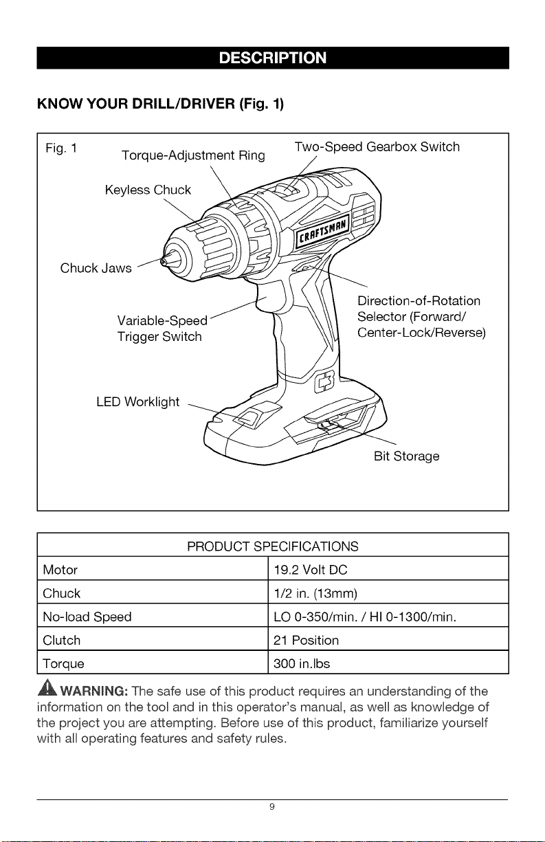
KNOW YOUR DRILL/DRIVER (Fig. 1)
Fig. 1 Torque-Adjustment Ring Two-Speed Gearbox Switch
Keyless_
Chuck Jaws J
1--
............ _ b _ Direction-of-Rotation
Variable-Speed \ Selector (Forward/
Trigger Switch 1 Center-L°cWReverse)
LED Worklight
Bit Storage
PRODUCT SPECIFICATIONS
Motor 19.2 Volt DC
Chuck 1/2 in. (13mm)
No-load Speed LO 0-350/min. / HI 0-1300/min.
Clutch 21 Position
Torque 300 in.lbs
,_ WARNmNG: The safe use of this product requires an understanding of the
information on the tool and in this operatods manual, as well as knowledge of
the project you are attempting. Before use of this product, familiarize yourself
with all operating features and safety rules.
ADJUSTABLE TORQUE
The drill/driver has a 21=position clutch: 1 drill position and 20 torque positions.
TWO-SPEED GEARBOX
The two=speed gearbox is designed for ddlling or driving at LO or HJ speeds.
A slide switch is located on top of your drill/driver for selecting the
appropriate speed.
VARIABLE SPEED
The variable=speed trigger switch delivers higher speed with increased trigger
pressure and Bower speed with decreased trigger pressure.
KEYLESS CHUCK
The keyless chuck allows you to hand=tighten or release the drill bit in the
chuck jaws.
FORWARD/CENTER-LOCK/REVERSE SELECTOR
The drill/driver has a direction=of=rotation selector located above the trigger
switch for changing the direction of bit rotation. Setting the trigger switch in the
OFF (center=lock) position helps reduce the possibility of accidental starting
when not in use.
LED WORKLIGHT
The LED worklight, located on the base of the drill/driver, illuminates when
the trigger switch is depressed. This feature provides extra light for
increased visibility.
10
_WARNING: If any parts are broken or missing, do not attempt to attach
the battery pack or operate the drill/driver until the broken or missing parts are
replaced. Failure to do so could result in possible serious injury.
WARNING: Do not attempt to modify this drill/driver or create accessories
not recommended for use with this drill/driver. Any such alteration or
modification is misuse and could result in a hazardous condition leading to
possible serious injury.
WARNING: To prevent accidental starting that could cause serious personal
injury, always remove the battery pack from the drill/driver when changing bits.
UNPACKING
This product has been shipped completely assembled.
• Carefully remove the tool and any accessories from the carton. Make sure
that all items listed in the packing list are included.
• Inspect the tool carefully to make sure no breakage or damage occurred
during shipping.
• Do not discard the packing material until you have carefully inspected and
satisfactorily operated the tool.
• If any parts are damaged or missing, please return the tool to the place
of purchase.
PACKING LIST
Drill/driver and operator's manual.
11
[e]"J:I,_:_i[e]_I
This product will accept Craftsman C3 19.2V lithium-ion battery packs. For
complete charging instructions, refer to the Operator's Manual for the battery
packs and chargers.
WARNING: To prevent accidental starting that could cause serious personal
injury, always remove the battery pack from the tool when assembling parts,
making adjustments, installing or removing bits, cleaning, or when it is not
in use.
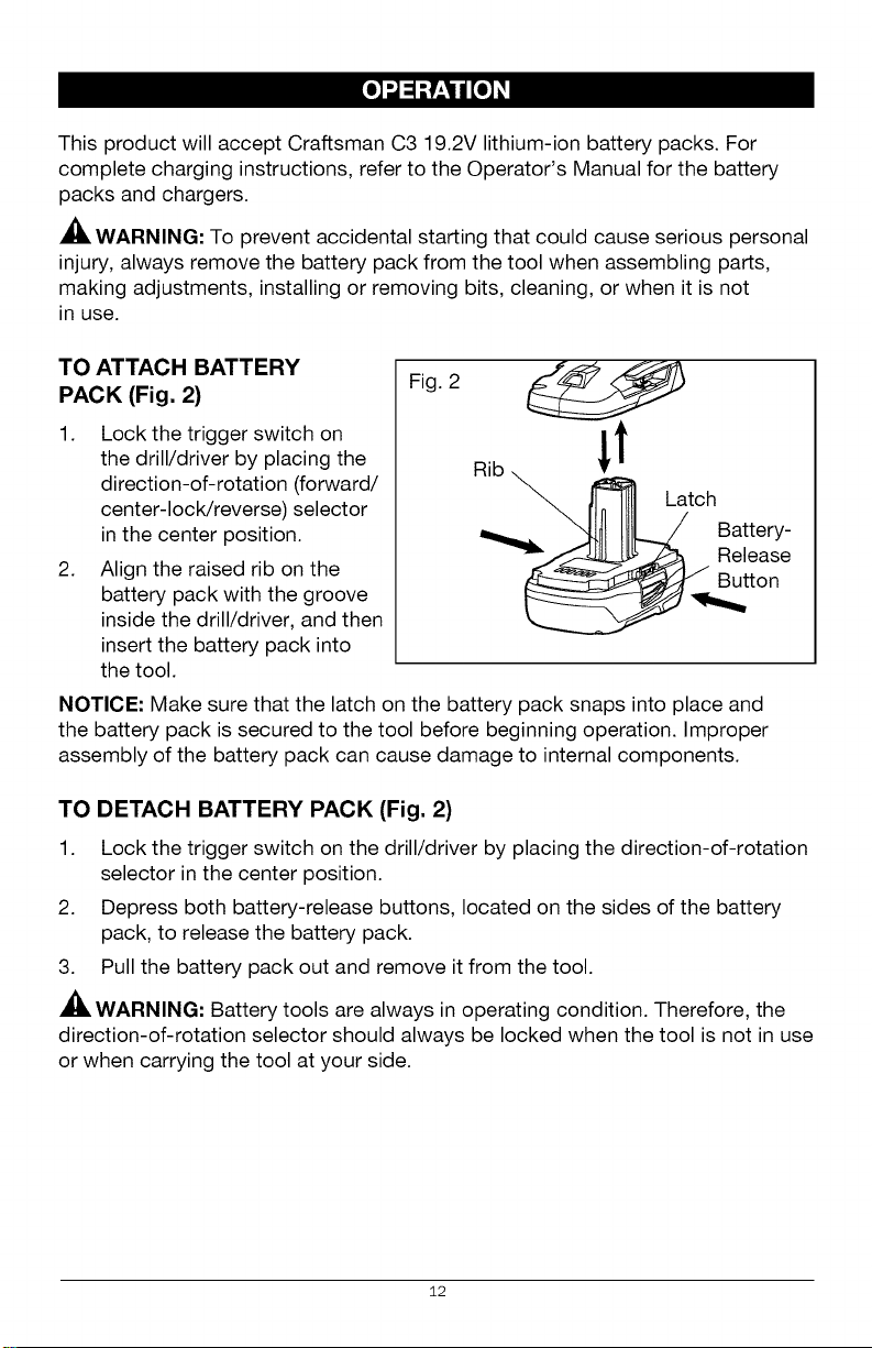
TO ATTACH BATTERY
PACK (Fig. 2)
1. Lock the trigger switch on
the drill/driver by placing the
direction-of-rotation (forward/
center-lock/reverse) selector
in the center position.
2. Align the raised rib on the
battery pack with the groove
inside the drill/driver, and then
insert the battery pack into
the tool.
NOTICE: Make sure that the latch on the battery pack snaps into place and
the battery pack is secured to the tool before beginning operation. Improper
assembly of the battery pack can cause damage to internal components.
Fig. 2
TO DETACH BATTERY PACK (Fig. 2)
1. Lock the trigger switch on the drill/driver by placing the direction-of-rotation
selector in the center position.
2. Depress both battery-release buttons, located on the sides of the battery
pack, to release the battery pack.
3. Pull the battery pack out and remove it from the tool.
WARNING: Battery tools are always in operating condition. Therefore, the
direction-of-rotation selector should always be locked when the tool is not in use
or when carrying the tool at your side.
12
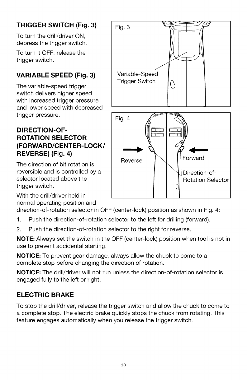
TRIGGER SWITCH (Fig. 3)
To turn the drill/driver ON,
depress the trigger switch.
To turn it OFF, release the
trigger switch.
Figvir3iable_Spee d I 1
VARIABLE SPEED (Fig. 3)
The variable-speed trigger
switch delivers higher speed
with increased trigger pressure
and lower speed with decreased
trigger pressure.
Trigger Switch .(_ I .I
Fig. 4
DIRECTION-OF-
ROTATION SELECTOR
(FORWARD/CENTER-LOCK/
REVERSE) (Fig. 4)
The direction of bit rotation is
reversible and is controlled by a
selector located above the
Reverse
I I "1,Direction-of-
trigger switch.
With the drill/driver held in
l _ R°tati°n Select°r
normal operating position and
direction-of-rotation selector in OFF (center-lock) position as shown in Fig. 4:
1. Push the direction-of-rotation selector to the left for drilling (forward).
2. Push the direction-of-rotation selector to the right for reverse.
NOTE: Always set the switch in the OFF (center-lock) position when tool is not in
use to prevent accidental starting.
NOTICE: To prevent gear damage, always allow the chuck to come to a
complete stop before changing the direction of rotation.
NOTICE: The drill/driver will not run unless the direction-of-rotation selector is
engaged fully to the left or right.
ELECTRIC BRAKE
To stop the drill/driver, release the trigger switch and allow the chuck to come to
a complete stop. The electric brake quickly stops the chuck from rotating. This
feature engages automatically when you release the trigger switch.
13
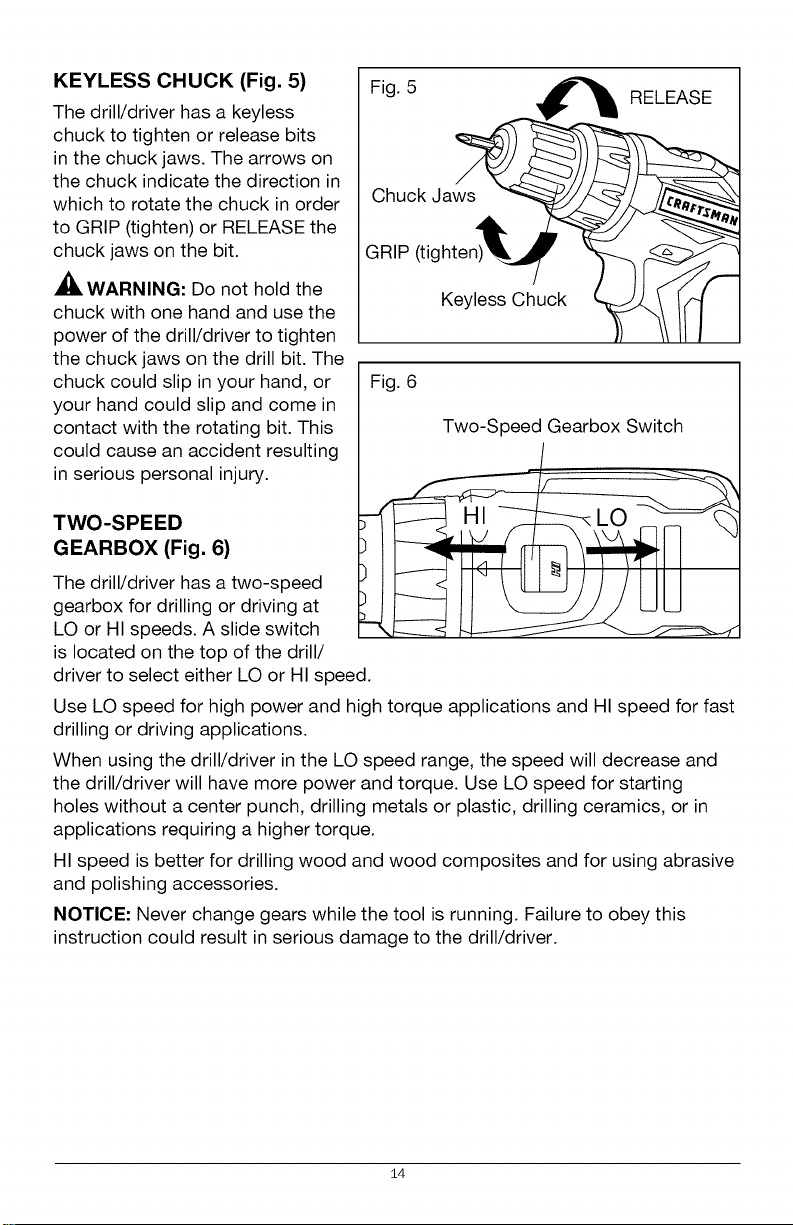
KEYLESS CHUCK (Fig. 5)
The drill/driver has a keyless
chuck to tighten or release bits
in the chuck jaws. The arrows on
the chuck indicate the direction in
which to rotate the chuck in order
to GRIP (tighten) or RELEASE the
chuck jaws on the bit.
WARNING: Do not hold the
chuck with one hand and use the
power of the drill/driver to tighten
the chuck jaws on the drill bit. The
chuck could slip in your hand, or
your hand could slip and come in
contact with the rotating bit. This
could cause an accident resulting
in serious personal injury.
Fig. 5
Chuck Jaws
GRIP (tighten)
Keyless Chuck
Fig. 6
Two-Speed Gearbox Switch
RELEASE
TWO-SPEED
GEARBOX (Fig. 6)
The drill/driver has a two-speed
gearbox for drilling or driving at
LO or HI speeds. A slide switch
is located on the top of the drill/
driver to select either LO or HI speed.
Use LO speed for high power and high torque applications and HI speed for fast
drilling or driving applications.
When using the drill/driver in the LO speed range, the speed will decrease and
the drill/driver will have more power and torque. Use LO speed for starting
holes without a center punch, drilling metals or plastic, drilling ceramics, or in
applications requiring a higher torque.
HI speed is better for drilling wood and wood composites and for using abrasive
and polishing accessories.
NOTICE- Never change gears while the tool is running. Failure to obey this
instruction could result in serious damage to the drill/driver.
14
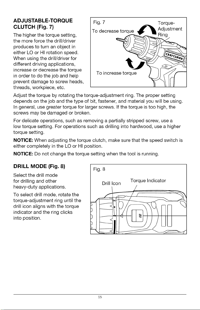
ADJUSTABLE-TORQUE
CLUTCH (Fig. 7)
TFogde7creasetorque _ Tdlqst_ent
The higher the torque setting,
the more force the drill/driver
produces to turn an object in
either LO or HI rotation speed.
When using the drill/driver for
different driving applications,
increase or decrease the torque
in order to do the job and help
prevent damage to screw heads,
To increase torq_ue_J_
threads, workpiece, etc.
Adjust the torque by rotating the torque-adjustment ring. The proper setting
depends on the job and the type of bit, fastener, and material you will be using.
In general, use greater torque for larger screws. If the torque is too high, the
screws may be damaged or broken.
For delicate operations, such as removing a partially stripped screw, use a
low torque setting. For operations such as drilling into hardwood, use a higher
torque setting.
NOTICE: When adjusting the torque clutch, make sure that the speed switch is
either completely in the LO or HI position.
NOTICE: Do not change the torque setting when the tool is running.
DRILL MODE (Fig. 8)
Select the drill mode
for drilling and other
heavy-duty applications.
To select drill mode, rotate the
torque-adjustment ring until the
drill icon aligns with the torque
indicator and the ring clicks
into position.
Fig. 8
Drill Icon Torque Indicator
15
 Loading...