

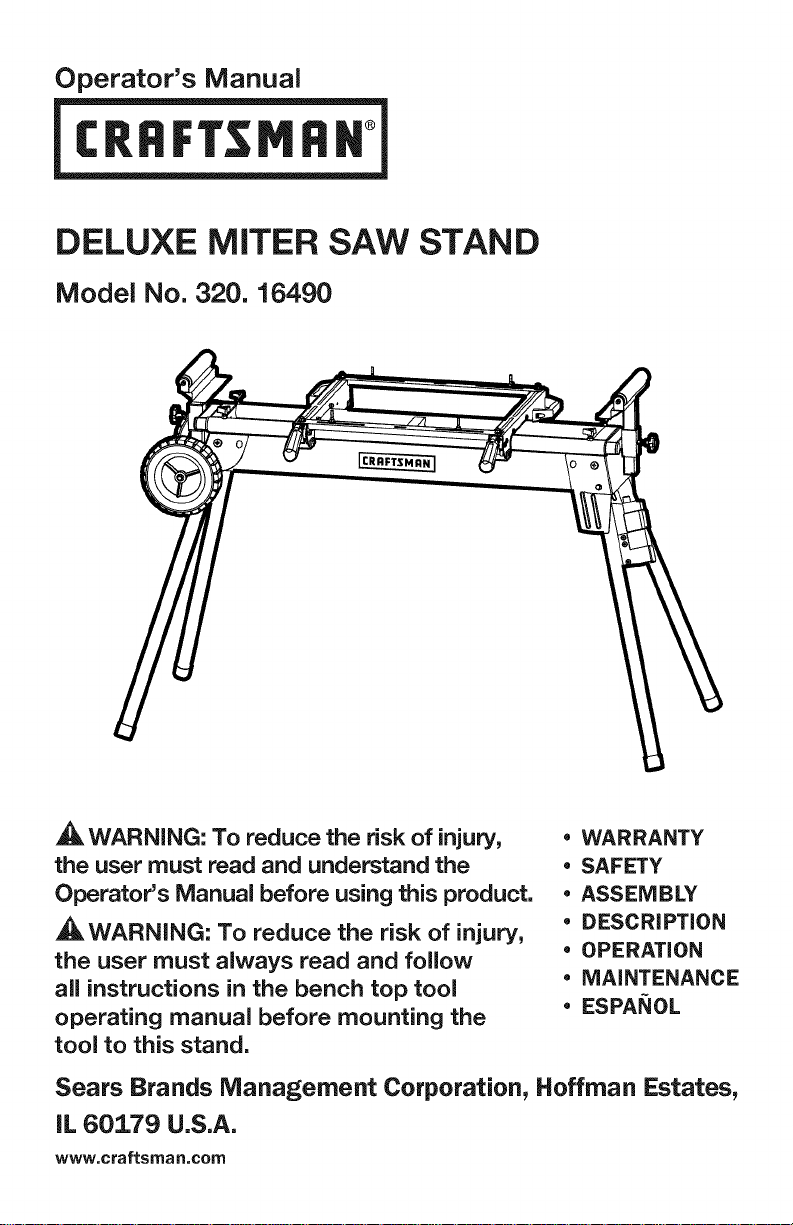
DELUXE MITER SAW STAND
Model No. 320. 16490
WARNING: To reduce the risk of injury,
the user must read and understand the
Operator's Manual before using this product.
_WARNING: To reduce the risk of injury,
the user must always read and follow
all instructions in the bench top tool
• WARRANTY
• SAFETY
• ASSEMBLY
• DESCRiPTiON
• OPERATION
• MAINTENANCE
• ESPANOL
operating manual before mounting the
tool to this stand.
Sears Brands Management Corporation, Hoffman Estates,
IL 60179 U.S.A.
www,craftsman,com

Warranty Page 2
Safety Symbols Pages 4-5
Safety Instructions Pages 6-7
Description Page 8
Assembly Pages 9-10
Operation Pages 11-18
Maintenance Page 18
Parts List Pages 19-21
CRAFTSMAN ONE YEAR FULL WARRANTY
FOR ONE YEAR from the date of purchase, this product is warranted
against any defects in material or workmanship. A defective product will be
replaced free of charge.
For warranty coverage details to obtain free replacement, visit the web
site: www.craftsman.com
This warranty is void if this product is ever used while providing commercial
services or if rented to another person.
This warranty gives you specific legal rights, and you may also have other
rights which vary from state to state.
Sears Brands Management Corporation, Hoffman Estates, IL 60179
This miter saw work stand has many features for making its use more pleasant
and enjoyable. Safety, performance, and dependability have been given top
priority in the design of this product making it easy to maintain and operate.
SAVE THESE iNSTRUCTiONS!
READ ALL iNSTRUCTiONS!
Page 2 16490 ManuaLRevised_12 0604
_,WARNING: Some dust created by power sanding, sawing, grinding, drilling
and other construction activities contains chemicals known to the state of
California to cause cancer, birth defects or other reproductive harm. Some
examples of these chemicals are:
• Lead from lead-based paints,
Crystalline silica from bricks and cement and other masonry products,and
Arsenic and chromium from chemically-treated lumber.
Your risk from these exposures varies, depending on how often you do this type
of work. To reduce your exposure to these chemicals: work in a well ventilated
area, and work with approved safety equipment, such as those dust masks that
are specially designed to filter out microscopic particles.
The purpose of safety symbols is to attract your attention to possible dangers.
The safety symbols and the explanations with them deserve your careful
attention and understanding. The symbol warnings do not, by themselves,
eliminate any danger. The instructions and warnings they give are no substitutes
for proper accident prevention measures.
16490 Manual_Revised_12-0604 Page 3
,_ WARNING: Be sure to read and understand all safety instructions in this
Operator's Manual, including all safety alert symbols such as "DANGER",
"WARNING", and "CAUTION" before using this stand. Failure to follow all
instructions listed below may result in electric shock, fire, and/or serious
personal injury.
SYMBOL SIGNAL MEANING
SAFETY ALERT SYMBOL: Indicates DANGER, WARNING, OR CAUTION; may
be used in conjunction with other symbols or pictographs.
,_ DANGER: Indicates a hazardous situation which, if not avoided, will result in
death or serious injury.
,_ WARNING: Indicates a hazardous situation which, if not avoided, could
result in death or serious injury.
_, CAUTION: Indicates a hazardous situation which, if not avoided, could result
in minor or moderate injury.
Damage prevention and Information Messages
These inform the user of important information and/or instructions that could
lead to equipment or other property damage if they are not followed. Each
message is preceded by the word "NOTICE", as in the example below:
NOTICE: Equipment and/or property damage may result if these instructions are
not followed.
,_, WARNING: To ensure safety and reliability, all repairs should be performed
by a qualified service technician.
_IL WARNING: The operation of any power tools can result in
foreign objects being thrown into your eyes, which can result
in severe eye damage. Before beginning power tool operation,
always wear safety goggles or safety glasses with side shield
and a full face shield when needed. We recommend a Wide
Vision Safety Mask for use over eyeglasses or standard safety
glasses with side shields. Always use eye protection that is
marked to comply with ANSI Z87.1.
Page 4 16490 Manual_Revised_12 0604
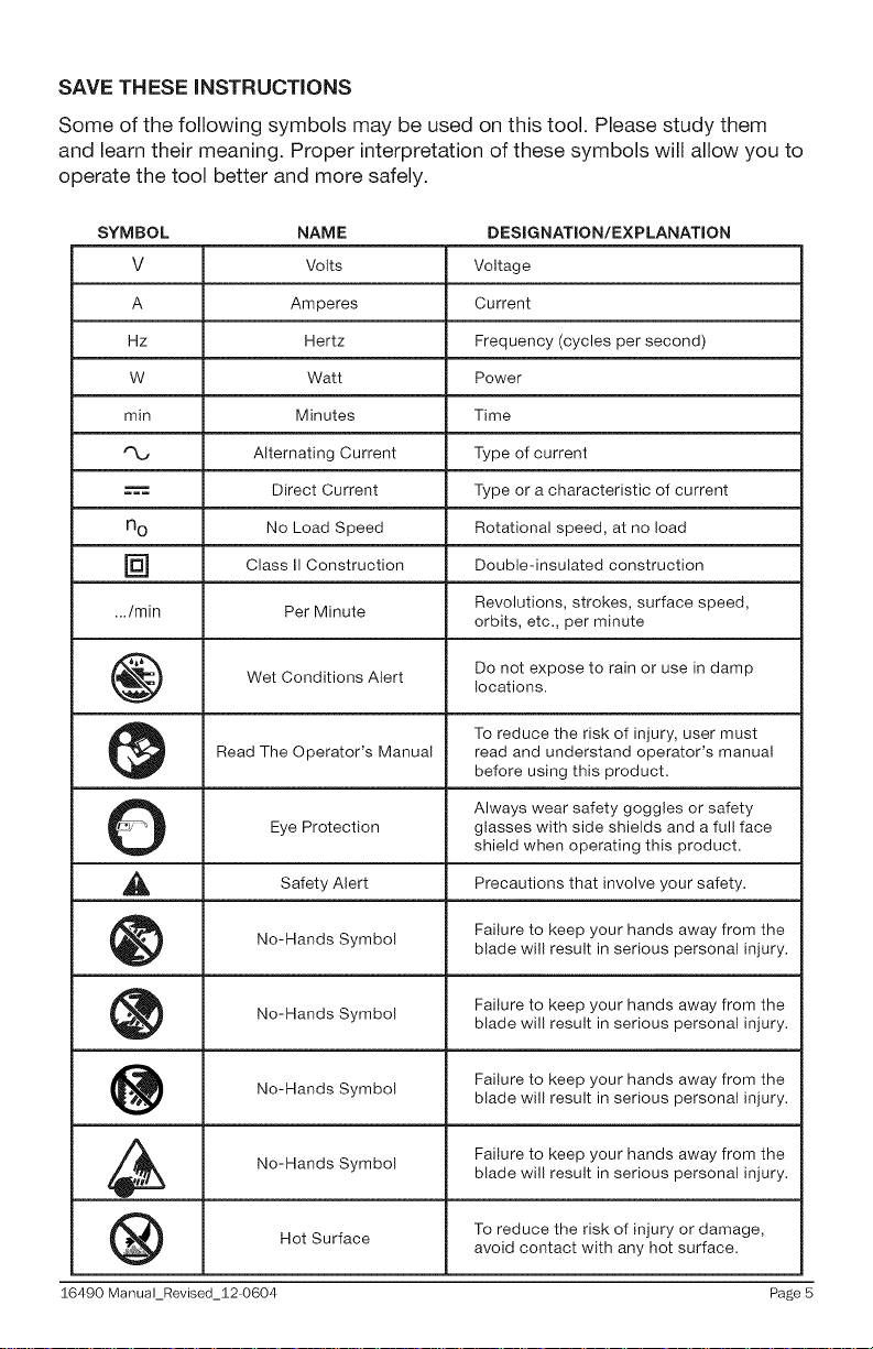
SAVE THESE iNSTRUCTiONS
Some of the following symbols may be used on this tool. Please study them
and learn their meaning. Proper interpretation of these symbols will allow you to
operate the tool better and more safely.
SYMBOL NAME DESIGNATION/EXPLANATION
V Volts Voltage
A Amperes Current
Hz Hertz Frequency (cycles per second)
W Watt Power
min Minutes Time
Alternating Current Type of current
====== Direct Current Type or a characteristic of current
n o No Load Speed Rotational speed, at no load
] Class II Construction Double-insulated construction
.../min Per Minute Revolutions, strokes, surface speed,
Wet Conditions Alert Do not expose to rain or use in damp
Read The Operator's Manual read and understand operator's manual
O Always wear safety goggles or safety
_1_ Alert Precautions that involve
Eye Protection glasses with side shields and a full face
Safety
No-Hands Symbol blade will result in serious personal injury.
No-Hands Failure to keep your hands away from the
No-Hands Symbol blade will result in serious personal injury.
No-Hands Symbol blade will result in serious personal injury.
Symbol
orbits, etc., per minute
locations.
To reduce the risk of injury, user must
before using this product.
shield when operating this product.
safety.
your
Failure to keep your hands away from the
blade will result in serious personal injury.
Failure to keep your hands away from the
Failure to keep your hands away from the
To reduce the risk of injury or damage,Hot Surface avoid contact with any hot surface.
16490 Manual_Revised_12-0604 Page 5
GENERAL SAFETY RULES
,_ WARNING: Read and understand all instructions. Failure to follow all
instructions in this Operator's Manual may result in electric shock, fire, and/or
serious personal injury.
Save all warnings and instructions for future reference.
READ AND SAVE THESE INSTRUCTIONS
,_ CAUTION: Do not modify or use this stand for any application other than
that for which it was designed.
ELECTRICAL SAFETY
= Power tool plugs must match the outlet. Never modify the plug in any
way. Do not use any adapter plugs with grounded power tools. Unmodified
plugs and matching outlets will reduce the risk of electric shock.
= Avoid body contact with grounded surfaces, such as pipes, radiators,
ranges, and refrigerators. There is an increased risk of electric shock if
your body is grounded.
= Do not expose power tools to rain or wet conditions. Water entering a
power tool will increase the risk of electric shock.
= Do not abuse the cord. Never use the cord for carrying, pulling, or
unplugging the power tool. Keep the cord away from heat, oil, sharp
edges, or moving parts. Damaged or entangled cords increase the risk of
electric shock.
When operating a power tool outdoors, use an extension cord suitable
for outdoor use. Use of a cord suitable for outdoor use reduces the risk of
electric shock.
if operating a power tool in a damp location is unavoidable, use a
ground fault circuit interrupter (GFCl} protected supply. Use of a GFCI
reduces the risk of electric shock.
SAFETY FOR WORK STAND
= Know your stand. Do not attempt to assemble or operate your miter saw
stand until you have read the safety instructions in this section.
= Only use your miter saw stand on a hard, dry and flat surface.
= Keep your work area clean and weU lit. Cluttered or dark areas invite accidents.
= Do not overreach. Keep proper footing and balance at all times.
= Do not load the miter saw stand with more than 330 Ibs.
Page 6 16490 ManuaLRevised_12 0604
• Store properly. Do not store the miter saw stand outdoors or in a
damp location.
• Do not stand or climb on miter saw stand. It could tip over, causing
serious injury.
• Do not permit children to use the stand unsupervised. It is not a toy.
• Be sure all locking pins are in the set-up position holes before using your
miter saw and miter saw miter saw stand.
= Take care when moving the stand, especially when a miter saw is mounted.
= Dress properly. Do not wear loose clothing or jewelry. Keep your hair,
clothing and gloves away from moving parts. Loose clothes, jewelry or long
hair can be caught in moving parts. Always wear non-slip footwear. Tie back
long hair. Roll long sleeves above the elbow.
= Always firmly attach the miter saw used with this stand. Do not attempt to
use the miter saw on your work stand until the miter saw is fastened firmly.
Be aware of tipping. When a large piece is cut from one end of a job, the
remaining piece may be heavy enough to tip the Miter Saw Stand. Always
ensure the workpiece is well supported.
Always keep all guards in place. Be sure all power tool guards are in good
working order and are in proper adjustment and alignment.
Always keep your hands away from the cutting area.
16490 Manual_Revised_12-0604 Page 7
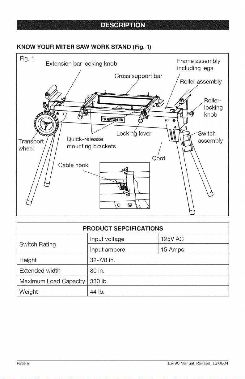
KNOW YOUR MITER SAW WORK STAND (Fig. 1}
Fig. 1
wheel
Extension bar locking knob
Quick-release
mounting brackets
Cable hook
PRODUCT SEPCIFICATIONS
Cross support bar
Lockin_ lever
Cord
Frame assembly
including legs
Roller-
locking
knob
}witch
assembly
Switch Rating
Height
Extended width
Maximum Load Capacity
Weight
Page 8 16490 ManuaLRevised_12 0604
Input voltage 125V AC
Input ampere 15 Amps
32-7/8 in.
80 in.
330 lb.
44 lb.
,_ WARNING: If any parts are broken or missing, do not attempt to operate the
stand until the broken or missing part is replaced. Failure to do so could result in
possible serious injury.
,_ WARNING: Do not attempt to modify this stand or create accessories not
recommended for use with this stand. Any such alteration or modification is
misuse and could result in a hazardous condition leading to serious injury.
UNPACKING
* Carefully remove all the parts and accessories from the carton. Make sure
that all the items listed in the packing list are included.
* Inspect the stand carefully to make sure no that breakage or damage
occurred during shipping.
* Do not discard the packing material until you have carefully inspected and
satisfactorily operated the stand.
* If any parts are damaged or missing, please return the stand to the place
of purchase.
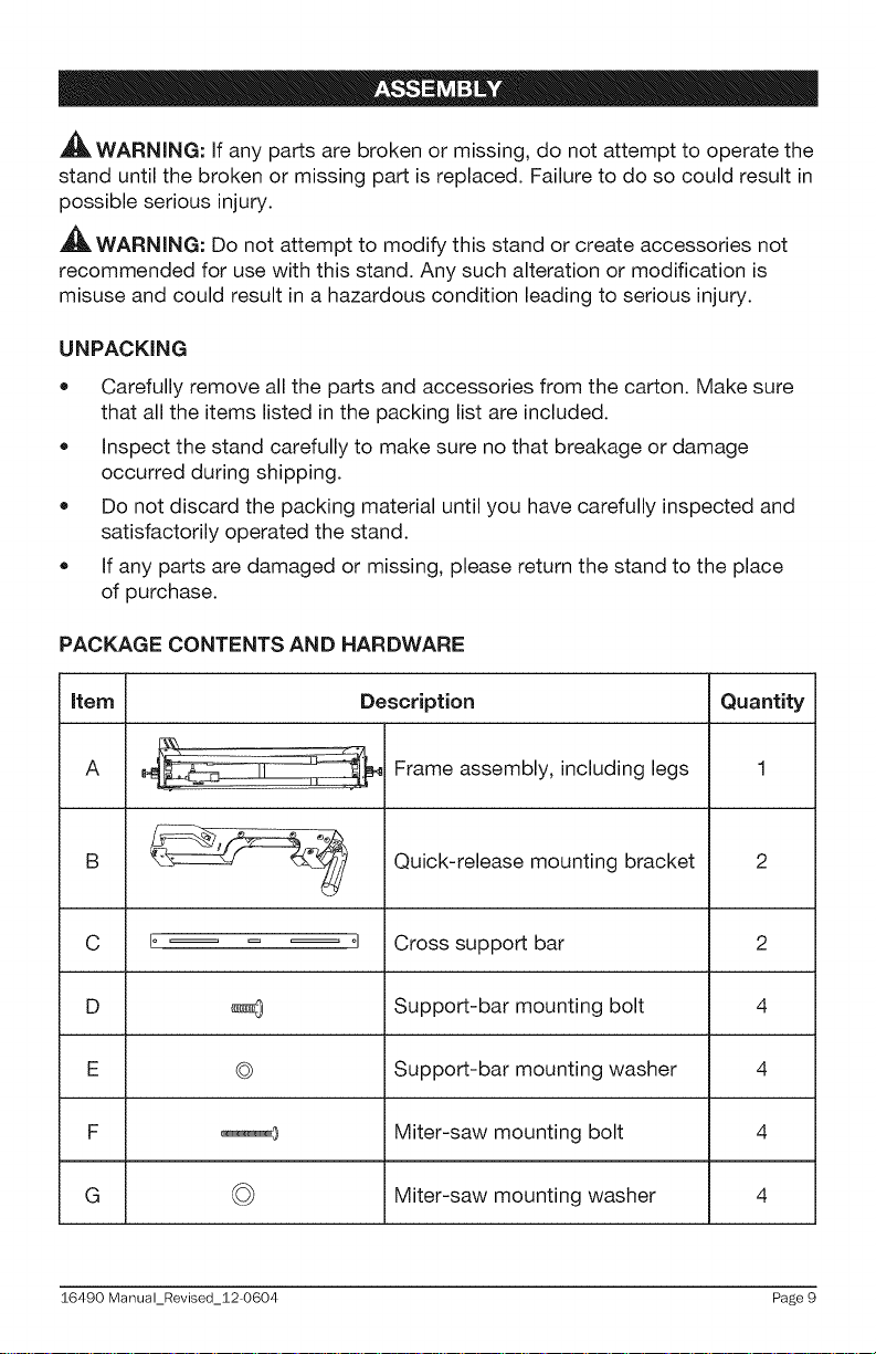
PACKAGE CONTENTS AND HARDWARE
item Quantity
A
_ Frame assembly, including legs
B
C zl Cross support bar 2
D Support-bar mounting bolt 4
E Support-bar mounting washer 4
F Miter-saw mounting bolt 4
G Miter-saw mounting washer 4
$6490 Manual_Revised_S2-0604 Page 9
©
©
Description
Quick-release mounting bracket
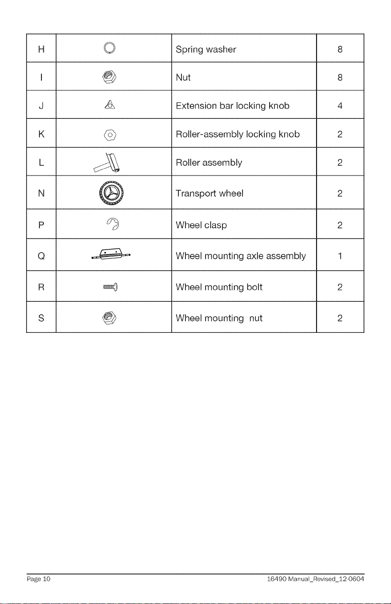
H 0 Spring washer 8
I @ Nut 8
J _ Extension bar locking knob 4
K _ Roller-assembly locking knob 2
L c:_ Roller assembly 2
N _ _ Transport wheel 2
p d_ Wheel clasp 2
Q Wheel mounting axle assembly 1
R _ Wheel mounting bolt 2
S _ Wheel mounting nut 2
Page 10 16490 ManuaLRevised_12 0604
A
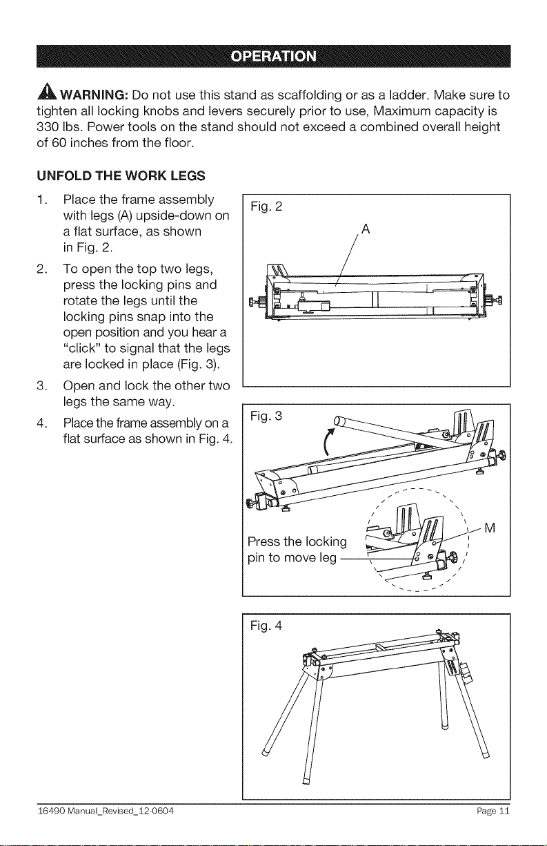
,_b, WARNING: Do not use this stand as scaffolding or as a ladder. Make sure to
tighten all locking knobs and levers securely prior to use, Maximum capacity is
330 Ibs. Power tools on the stand should not exceed a combined overall height
of 60 inches from the floor.
UNFOLD THE WORK LEGS
1. Place the frame assembly
with legs (A) upside-down on
a flat surface, as shown
in Fig. 2.
2. To open the top two legs,
press the locking pins and
rotate the legs until the
locking pins snap into the
open position and you hear a
"click" to signal that the legs
are locked in place (Fig. 3).
3. Open and lock the other two
legs the same way.
4. Place the frame assembly on a
flat surface as shown in Fig. 4.
Fig. 2
A
/ \
M/ _
Press the locking
3in to move leg _,//"
Fig. 4
16490 Manual_Revised_12-0604 Page 11
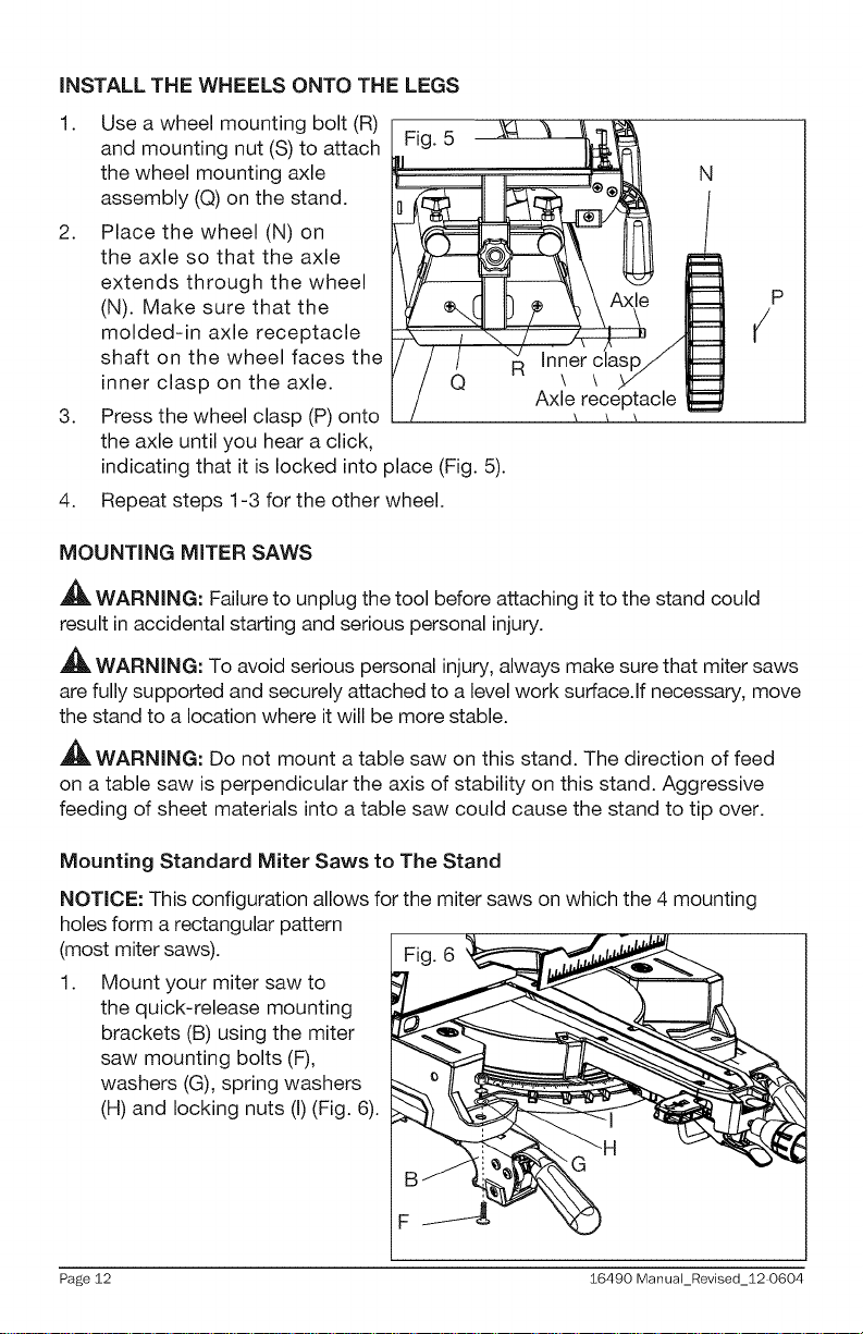
iNSTALL THE WHEELS ONTO THE LEGS
1.
Use a wheel mounting bolt (R)
and mounting nut (S) to attach Fig. 5
the wheel mounting axle
N
assembly (Q) on the stand.
2.
Place the wheel (N) on
the axle so that the axle
extends through the wheel
(N). Make sure that the
molded-in axle receptacle
shaft on the wheel faces the
inner clasp on the axle.
3.
Press the wheel clasp (P) onto
the axle until you hear a click,
indicating that it is locked into place (Fig. 5).
4.
Repeat steps 1-3 for the other wheel.
MOUNTING MITER SAWS
_1_ WARNING: Failure to unplug the tool before attaching it to the stand could
result in accidental starting and serious personal injury.
WARNING: To avoid serious personal injury, always make sure that miter saws
are fully supported and securely attached to a level work surface.If necessary, move
the stand to a location where it will be more stable.
,_ WARNING: Do not mount a table saw on this stand. The direction of feed
on a table saw is perpendicular the axis of stability on this stand. Aggressive
feeding of sheet materials into a table saw could cause the stand to tip over.
Mounting Standard Miter Saws to The Stand
NOTICE: This configuration allows for the miter saws on which the 4 mounting
holes form a rectangular pattern
(most miter saws).
1. Mount your miter saw to
the quick-release mounting
brackets (B) using the miter
saw mounting bolts (F),
washers (G), spring washers
(H) and locking nuts (I) (Fig. 6).
Page 12 16490 ManuaLRevised_12 0604
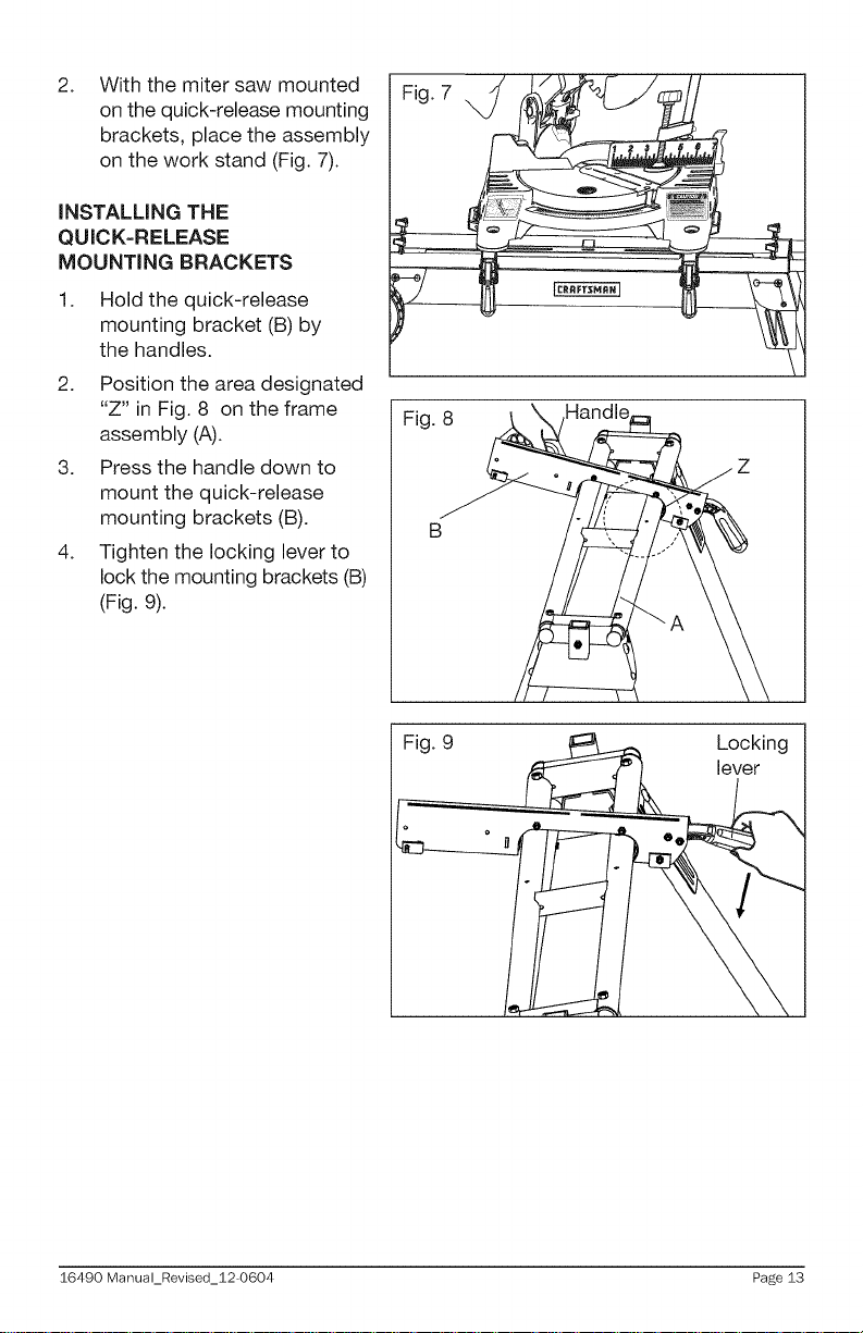
With the miter saw mounted
2. Fig. 7
on the quick-release mounting
brackets, place the assembly
on the work stand (Fig. 7).
iNSTALLiNG THE
QUICK=RELEASE
MOUNTING BRACKETS
1.
Hold the quick-release
mounting bracket (B) by
the handles.
2. Position the area designated
"Z" in Fig. 8 on the frame
assembly (A).
3. Press the handle down to
mount the quick-release
mounting brackets (B).
4. Tighten the locking lever to
lock the mounting brackets (B)
(Fig. 9).
Fig. 8
B
\
Fig. 9 _ Locking
16490 Manual_Revised_12-0604 Page 13
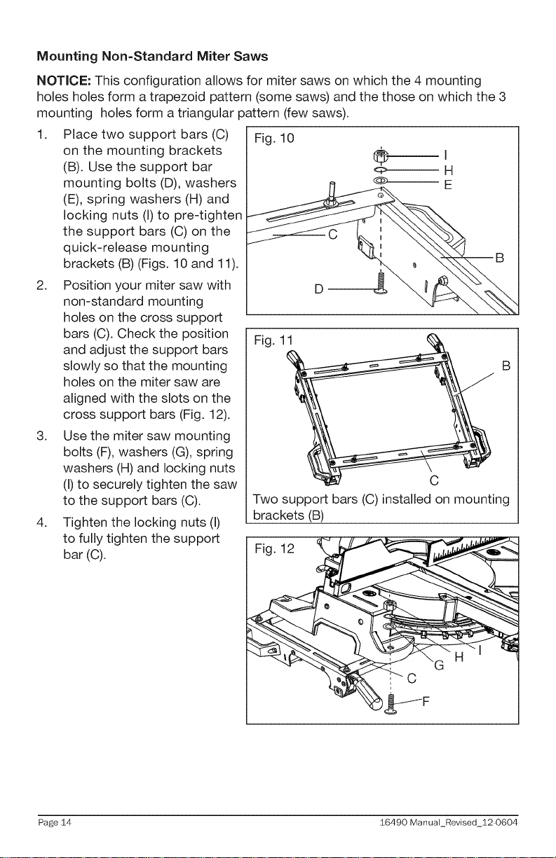
Mounting Non=Standard Miter Saws
NOTICE: This configuration allows for miter saws on which the 4 mounting
holes holes form a trapezoid pattern (some saws) and the those on which the 3
mounting holes form a triangular pattern (few saws).
1. Place two support bars (C)
on the mounting brackets
(B). Use the support bar
mounting bolts (D), washers
(E), spring washers (H) and
locking nuts (I) to pre-tighten
the support bars (C) on the
quick-release mounting
brackets (B) (Figs. 10 and 11).
2. Position your miter saw with
non-standard mounting
holes on the cross support
bars (C). Check the position
and adjust the support bars
slowly so that the mounting
holes on the miter saw are
aligned with the slots on the
cross support bars (Fig. 12).
3. Use the miter saw mounting
bolts (F), washers (G), spring
washers (H) and locking nuts
(I)to securely tighten the saw
to the support bars (C).
4. Tighten the locking nuts (I)
to fully tighten the support
bar (C).
Fig. 10
Fig. 11
C
Two support bars (C)installed on mounting
brackets (B)
Fig. 12
B
C
Page 14 16490 Manual_Revised_12 0604
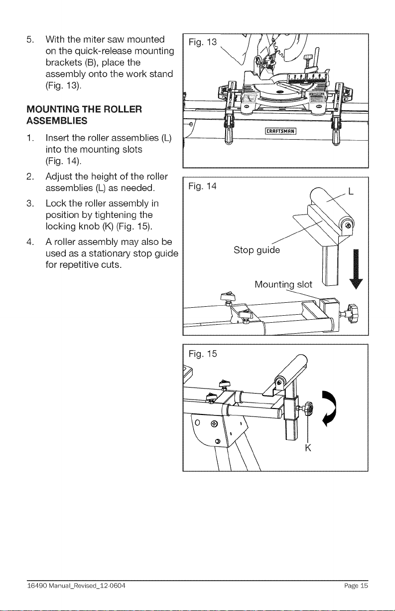
5. With the miter saw mounted
on the quick-release mounting
brackets (B), place the
assembly onto the work stand
(Fig. 13).
MOUNTING THE ROLLER
ASSEMBLIES
1. Insert the roller assemblies (L)
into the mounting slots
(Fig. 14).
2. Adjust the height of the roller
assemblies (L) as needed.
3. Lock the roller assembly in
position by tightening the
locking knob (K) (Fig. 15).
4. A roller assembly may also be
used as a stationary stop guide
for repetitive cuts.
Fig. 14
St°p_ii
Fig. 15
K
16490 Manual_Revised_12-0604 Page 15
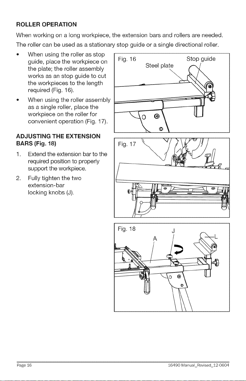
ROLLER OPERATION
When working on a long workpiece, the extension bars and rollers are needed.
The roller can be used as a stationary stop guide or a single directional roller.
• When using the roller as stop
guide, place the workpiece on
the plate; the roller assembly
works as an stop guide to cut
the workpieces to the length
required (Fig. 16).
When using the roller assembly
as a single roller, place the
workpiece on the roller for
convenient operation (Fig. 17).
ADJUSTING THE EXTENSION
BARS (Fig. 18}
1. Extend the extension bar to the
required position to properly
support the workpiece.
2. Fully tighten the two
extension-bar
locking knobs (J).
I
Fig. 16 Stop guide
Steel plate
Fig. 17
Fig. 18
A
Page 16 16490 ManuaLRevised_12 0604
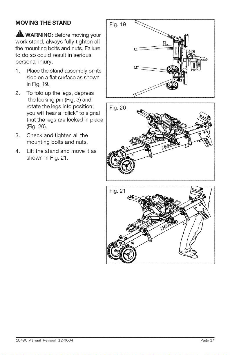
MOVING THE STAND
WARNING: Before moving your
work stand, always fully tighten all
the mounting bolts and nuts. Failure
to do so could result in serious
personal injury.
1. Place the stand assembly on its
side on a flat surface as shown
in Fig. 19.
2. To fold up the legs, depress
the locking pin (Fig. 3) and
rotate the legs into position;
you will hear a "click" to signal
that the legs are locked in place
(Fig. 20).
3. Check and tighten all the
mounting bolts and nuts.
4. Lift the stand and move it as
shown in Fig. 21.
Fig. 19
Fig. 20
Fig. 21
16490 Manual_Revised_12-0604 Page 17
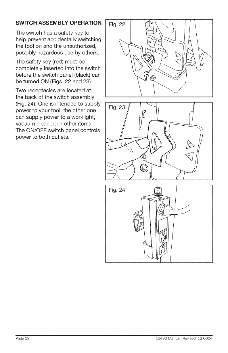
SWITCH ASSEMBLY OPERATION
The switch has a safety key to
help prevent accidentally switching
the tool on and the unauthorized,
possibly hazardous use by others.
The safety key (red) must be
completely inserted into the switch
before the switch panel (black) can
be turned ON (Figs. 22 and 23).
Two receptacles are located at
the back of the switch assembly
(Fig. 24). One is intended to supply
power to your tool; the other one
can supply power to a worklight,
vacuum cleaner, or other items.
The ON/OFF switch panel controls
power to both outlets.
Fig. 22
Fig. 24
J
Page 18 16490 ManuaLRevised_12 0604
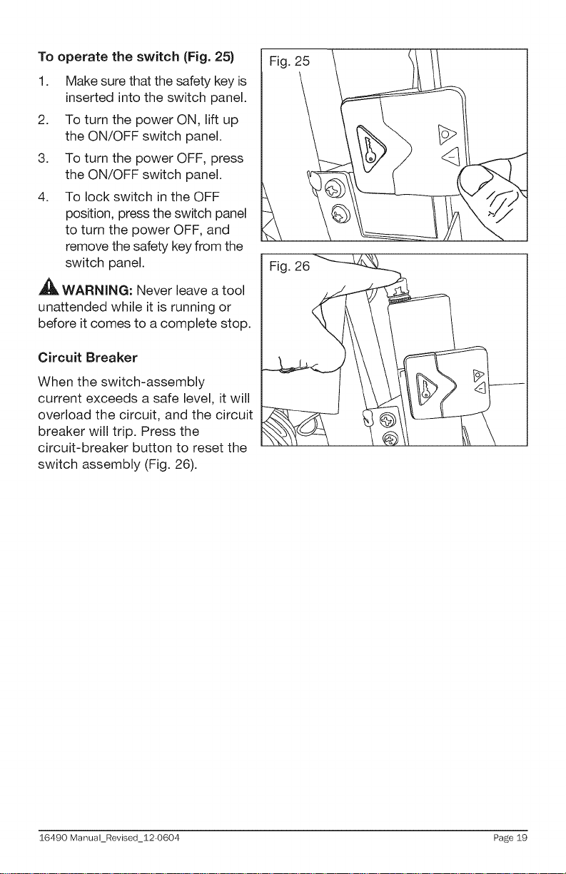
To operate the switch (Fig. 25)
1. Make sure that the safety key is
inserted into the switch panel.
2. To turn the power ON, lift up
the ON/OFF switch panel.
3. To turn the power OFF, press
the ON/OFF switch panel.
4. To lock switch in the OFF
position, press the switch panel
to turn the power OFF, and
remove the safety key from the
switch panel.
,_ WARNING: Never leave a tool
unattended while it is running or
before it comes to a complete stop.
Circuit Breaker
When the switch-assembly
current exceeds a safe level, it will
overload the circuit, and the circuit
breaker will trip. Press the
circuit-breaker button to reset the
switch assembly (Fig. 26).
Fig. 25
16490 Manual_Revised_12-0604 Page 19
,_ WARNING: When servicing, use only identical replacement parts. Use of any
other parts may create a hazard or cause product damage.
GENERAL MAINTENANCE
Avoid using solvents when cleaning plastic parts. Most plastics are susceptible
to damage from various types of commercial solvents and may be damaged by
their use. Use clean cloths to remove dirt, dust, oil, grease, etc.
WARNING: When servicing, use only identical replacement parts. Use of any
other parts may create a hazard or cause product damage. To ensure safety and
reliability, all repairs should be performed by a qualified service technician.
,_WARNING: Keep the miter saw stand dry, clean, and free from oil and
grease. Always use a clean cloth when cleaning. Never use brake fluids,
gasoline, petroleum based products or any strong solvent to clean the bench
grinder stand. Chemicals can damage, weaken or destroy plastic which may
result in serious personal injury.
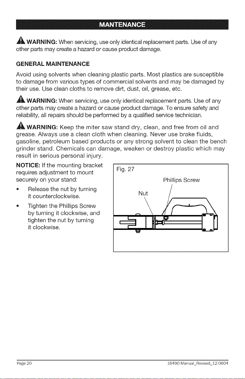
NOTICE: If the mounting bracket
requires adjustment to mount Fig. 27
securely on your stand: Phillips Screw
* Release the nut by turning
it counterclockwise. Nut
Tighten the Phillips Screw
by turning it clockwise, and
tighten the nut by turning
it clockwise.
Page 20 16490 ManuaLRevised_12 0604
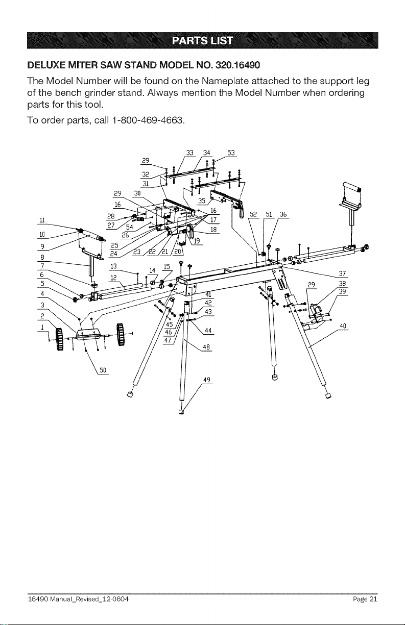
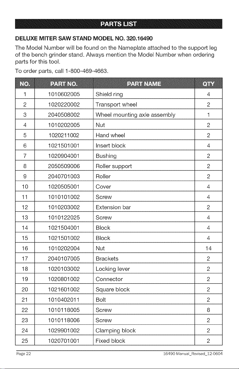
DELUXE MITER SAWSTAND MODEL NO. 320.16490
The Model Number will be found on the Nameplate attached to the support leg
of the bench grinder stand. Always mention the Model Number when ordering
parts for this tool.
To order parts, call 1-800-469-4663.
29
32
31
29 30 \
16
Ii
IO
9
8
7
6
5
4
3
28 52 51 36
33 34 53
48
/
I
37
38
4o
16490 Manual_Revised_12-0604 Page 21
DELUXE MITER SAW STAND MODEL NO. 320.16490
The Model Number will be found on the Nameplate attached to the support leg
of the bench grinder stand. Always mention the Model Number when ordering
parts for this tool.
To order parts, call 1-800-469-4663.
1010602005 Shield ring 4
2 1020220002 Transport wheel 2
3 2040508002 Wheel mounting axle assembly 1
4 1010202005 Nut 2
5 1020211002 Hand wheel 2
6 1021501001 Insert block 4
7 1020904001 Bushing 2
8 2050509006 Roller support 2
9 2040701003 Roller 2
10 1020505001 Cover 4
11 1010101002 Screw 4
12 1010203002 Extension bar 2
13 1010122025 Screw 4
14 1021504001 Block 4
15 1021501002 Block 4
16 1010202004 Nut 14
17 2040107005 Brackets 2
18 1020103002 Locking lever 2
19 1020801002 Connector 2
20 1021601002 Square block 2
21 1010402011 Bolt 2
22 1010118005 Screw 8
23 1010118006 Screw 2
24 1029901002 Clamping block 2
25 1020701001 Fixed block 2
Page 22 16490 ManuaLRevised_12 0604
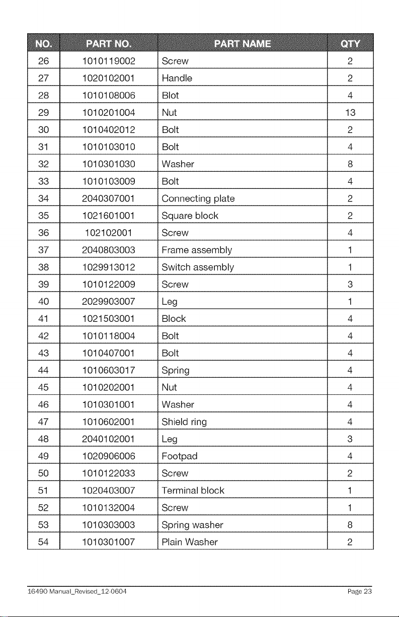
1010119002 Screw 2
27 1020102001 Handle 2
28 1010108006 Blot 4
29 1010201004 Nut 13
30 1010402012 Bolt 2
31 1010103010 Bolt 4
32 1010301030 Washer 8
33 1010103009 Bolt 4
34 2040307001 Connecting plate 2
35 1021601001 Square block 2
36 102102001 Screw 4
37 2040803003 Frame assembly 1
38 1029913012 Switch assembly 1
39 1010122009 Screw 3
40 2029903007 Leg 1
41 1021503001 Block 4
42 1010118004 Bolt 4
43 1010407001 Bolt 4
44 1010603017 Spring 4
45 1010202001 Nut 4
46 1010301001 Washer 4
47 1010602001 Shield ring 4
48 2040102001 Leg 3
49 1020906006 Footpad 4
50 1010122033 Screw 2
51 1020403007 Terminal block 1
52 1010132004 Screw 1
53 1010303003 Spring washer 8
54 1010301007 Plain Washer 2
16490 Manual_Revised_12-0604 Page 23
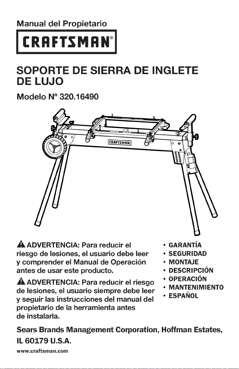
Manual del Propietario
SOPORTE DE SIERRA DE
DE LUJO
Modelo N° 320.16490
ADVERTENCIA: Para reducir el
riesgo de lesiones, el usuario debe leer
y comprender el Manual de Operaci6n
antes de usar este producto.
ADVERTENCIA: Para reducir el riesgo
de lesiones, el usuario siempre debe leer
y seguir las instrucciones del manual del
propietario de la herramienta antes
de instalarla.
INGLETE
• GARANTiA
• SEGURIDAD
• NIONTAJE
• DESCRIPCION
• OPERACi6N
• MANTENIMIENTO
• ESPANOL
Sears Brands Management Corporation, Hoffman Estates,
IL 60179 U.S.A.
www,craftsman,com
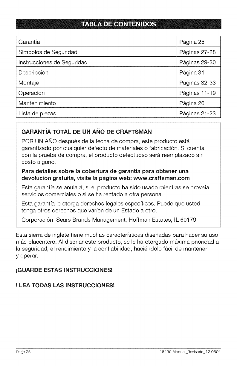
Garantia Pagina 25
Simbolos de Seguridad Paginas 27-28
Instrucciones de Seguridad Paginas 29-30
Descripcion Pagina 31
Montaje Paginas 32-33
Operacion Paginas 11-19
Mantenimiento Pagina 20
Lista de piezas Paginas 21-23
GARANTiA TOTAL DE UN A_lO DE CRAFTSMAN
POR UN ANO despues de la fecha de compra, este producto esta
garantizado por cualquier defecto de materiales o fabricaci6n. Si cuenta
con la prueba de compra, el producto defectuoso sera reemplazado sin
costo alguno.
Para detalles sobre la cobertura de garantia para obtener una
devoluci6n gratuita, visite la p_gina web: www.craftsman.com
Esta garantia se anulara, si el producto ha sido usado mientras se proveia
servicios comerciales o si se ha rentado a otra persona.
Esta garantia le otorga derechos legales especificos. Puede que usted
tenga otros derechos que varien de un Estado a otro.
Corporacion Sears Brands Management, Hoffman Estates, IL 60179
Esta sierra de inglete tiene muchas caracteristicas disefiadas para hacer su uso
mas placentero. AI disefiar este producto, se le ha otorgado maxima prioridad a
la seguridad, el rendimiento y la confiabilidad, haciendolo facil de mantener
y operar.
iGUARDE ESTAS INSTRUCCIONES!
! LEA TODAS LAS INSTRUCCIONES!
Page 25 16490 ManuaLRevisado_12 0604
,_ ADVERTENClA: Algunas particulas de polvo que se generan al lijar,
serruchar, afilar, o perforar, con herramientas electricas, asi como las
actividades de construccion, contienen quimicos que el estado de California
reconoce como causantes de cancer, nacimientos defectuosos u otros daSos
reproductivos. Algunos ejemplos de estos quimicos son:
• Plomo de pinturas hechas a base de plomo
Silice cristalizado de ladrillos y cemento y otros productos de albaSileria, y
Arsenio y cromo de la madera tratada quimicamente
El riesgo por el contacto con estos quimicos, varia dependiendo de cuan
frecuente realice este tipo de trabajo. Para reducir el contacto con estos
quimicos: trabaje en un Area bien ventilada, y con equipo con seguridad
aprobada; tales como mascaras para el polvo que esten especialmente
dise_adas para filtrar las particulas microscopicas.
El proposito de los simbolos de seguridad es el de dirigir su atencion hacia
los peligros posibles. Los simbolos de seguridad y las explicaciones que los
acompaSan merecen una cuidadosa atencion y entendimiento. Los simbolos
de advertencia no eliminan los peligros pot si mismos. Las instrucciones y
advertencias que proveen no son sustitutas de las medidas adecuadas de
prevencion de accidentes.
16490 Manual_Revisado_12-0604 Page 26
_, ADVERTENClA: AsegOrese de leer y comprender todas las instrucciones
de seguridad en este manual de operacion, incluyendo todos los simbolos
de seguridad de alerta tales como "PELIGRO", "ADVERTENClA", y
"PRECAUClON" antes de usar esta herramienta. El no seguir todas las
instrucciones que se indican a continuacion, puede ocasionar descarga
electrica, incendio, y/o grave lesion personal.
SIGNIFICADO DE LOS SIMBOLOS
SiMBOLO DE SEGURIDAD DE ALERTA: indica PELIGRO, ADVERTENCIA, o
PRECAUCION; pueden set usados junto con otros simbolos o pictogramas.
,_ PELIGRO: indica una situacion peligrosa que de no ser evitada, producira la
muerte o lesion grave.
,_ ADVERTENClA: indica una situacion potencialmente peligrosa que de no
set evitada, podria producir la muerte o lesion grave.
,_ PRECAUClON: indica una situacion potencialmente peligrosa que de no
set evitada podria producir lesiones menores o moderadas.
Prevenci6n de daSo y mensajes informativos
Le informan al usuario de informacion importante y/o instrucciones que podrian
producir daSo al equipo u otra propiedad si no se cumplen. Cada mensaje esta
precedido por la palabra "NOTA", como se muestra en el ejemplo aqui abajo:
AVlSO: Da_o al equipo u/o otra propiedad puede producirse si no se cumplen
estas instrucciones.
,_ ADVERTENClA: para asegurarse la seguridad y la confiabilidad, todas las
reparaciones deben realizarse pot un tecnico de servicio calificado.
_k
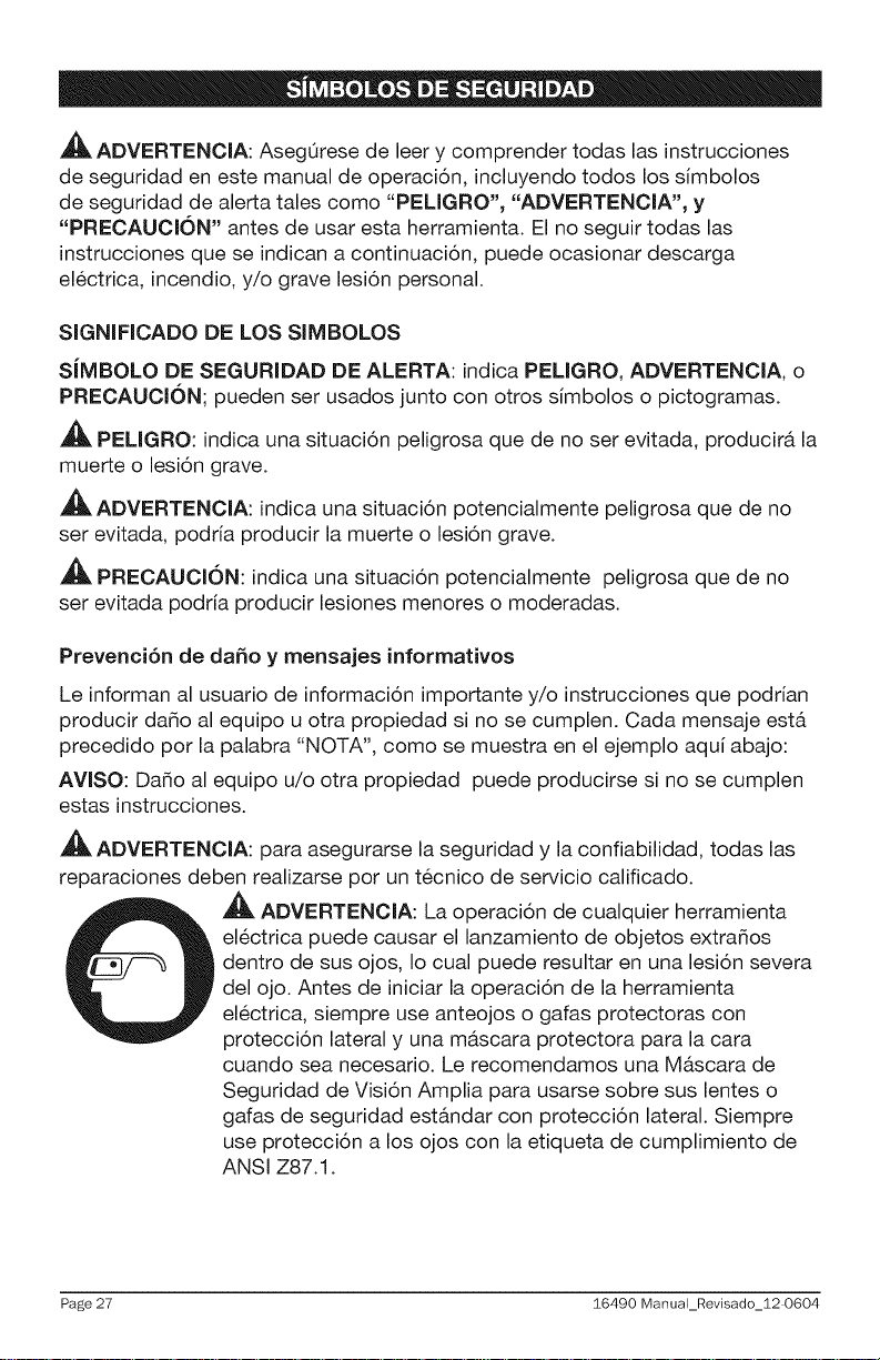
,_ ADVERTENClA: La operacion de cualquier herramienta
electrica puede causar el lanzamiento de objetos extraSos
dentro de sus ojos, Io cual puede resultar en una lesion severa
del ojo. Antes de iniciar la operacion de la herramienta
electrica, siempre use anteojos o gafas protectoras con
proteccion lateral y una mascara protectora para la cara
cuando sea necesario. Le recomendamos una MAscara de
Seguridad de Vision Amplia para usarse sobre sus lentes o
gafas de seguridad estandar con proteccion lateral. Siempre
use proteccion a los ojos con la etiqueta de cumplimiento de
ANSI Z87.1.
Page 27 :$6490 Manual_Revisado_12 0604
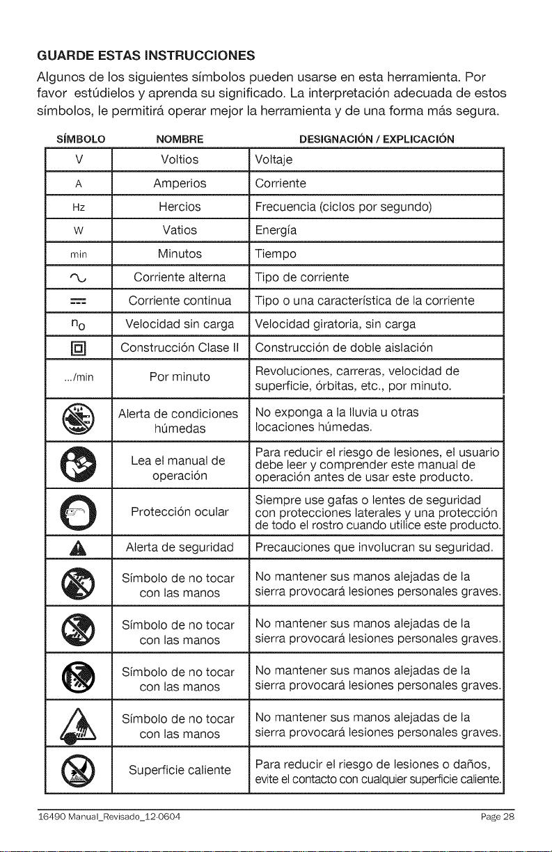
GUARDE ESTAS INSTRUCCIONES
Algunos de los siguientes simbolos pueden usarse en esta herramienta. Por
favor est6dielos y aprenda su significado. La interpretacion adecuada de estos
simbolos, le permitir& operar mejor la herramienta y de una forma mas segura.
SJMBOLO NOMBRE DESIGNACl6N / EXPLICACl6N
V Voltios Voltaje
A Amperios Corriente
Hz Hercios Frecuencia (ciclos por segundo)
w Vatios Energia
min Minutos Tiempo
"%, Corriente alterna Tipo de corriente
Corriente continua Tipo o una caracteristica de la corriente
no Velocidad sin carga Velocidad giratoria, sin carga
[] Construcci6n Ctase II Construcci6n de dobte aislaci6n
.../min Por minuto Revoluciones, carreras, velocidad de
superficie, 6rbitas, etc., por minuto.
Aterta de condiciones No exponga a la Iluvia u otras
hOmedas Iocaciones hOmedas.
Lea et manual de debe leer y comprender este manual de
operaci6n operaci6n antes de usar este producto.
O Siempre use gafas o lentes de seguridad
Protecci6n ocular con protecciones laterales y una protecci6n
Para reducir et riesgo de lesiones, et usuario
de todo el rostro cuando utilice este producto.
_1_ Aterta de seguridad Precauciones que involucran su seguridad.
Simbolo de no tocar No mantener sus manos atejadas de la
con las manos sierra provocara lesiones personales graves.
Simbolo de no tocar No mantener sus manos alejadas de la
con las manos sierra provocara lesiones personales graves.
Simbolo de no tocar No mantener sus manos atejadas de la
con las manos sierra provocara lesiones personales graves.
Simbolo de no tocar No mantener sus manos alejadas de lacon las manos sierra provocara lesiones personales graves.
Superficie caliente Para reducir el riesgo de lesiones o daNos,
eviteel contacto con cualquier superficie caliente.
16490 Manual_Revisado_12-0604 Page 28
 Loading...