

Craftsman 316.796140 Operator's Manual

Operator's Manual
4-Cycle
WEEDWACKER ®GAS TRIMMER
Model No. 316.796140
INCREN.RILL_r-(_
• SAFETY
• ASSEMBLY
• OPERATION
• MAINTENANCE
• PARTS LIST
• ESPANOL, R 17
CAUTION: Before using
\
this product, read this
manual and follow all
safety rules and operating
instructions.
Sears, Roebuck and Co., Hoffman Estates, IL 60179, U.S.A.
Visitour website: www, sears.com/craftsman
769-02059
CALIFORNIAPROPOSITION65WARNING
THE ENGINE EXHAUST FROM THIS PRODUCT CONTAINS
CHEMICALS KNOWN TO THE STATE OF CALIFORNIA TO
CAUSE CANCER, BIRTH DEFECTS OR OTHER
REPRODUCTIVE HARM,
TABLE OF CONTENTS
Rules for Safe Operation .......................... 2
Warranty Information ............................. 4
Assembly Instructions ............................ 5
Know Your Ung ................................. 5
Oil and Fuel Information ........................... 6
Stading/Stopping Instructions ...................... 7
Operating Instructions ............................ 8
Maintenance and Repair Instructions ............... 10
Cleaning and Storage ........................... 13
Troubleshooting Chart ........................... 14
Specifications ................................. 14
Parts Uet ..................................... 32
Service Numbers ........................ Backcover
SPARK ARRESTOR NOTE
NOTE: For users on U.S. Forest Land and in the states of
California, Maine, Oregon and Washington. All U.S. Forest
Land and the state of California (Public Resources Codes 4442
and 4443), Oregon and Washington require, by law that certain
internal combustion engines operated on forest brush and/or
grass-covered areas be equipped with a spark arrestor,
maintained in effective working order, or the engine be
constructed, equipped and maintained for the prevention of
fire. Check with your state or local authorities for regulations
pertaining to these requirements. Failure to follow these
requirements could subject you to liability or a fine. This unit is
factory equipped with a spark arrestor, If g requires
replacement, ask a Sears or other qualified service dealer to
install the Accessory Part #753-05297 Spark Arrestor Kit.
I A I the safety rules. Please reed these inetruetions
WARNING: When using the unit. you must follow
before operating the unit in order to ensure the
safety of the operator and any bystanders. Please
keep these instructions for later use.
All information, illustrations, and specifications in this manual
are based on the latest product information available at the
time of printing. We reserve the right to make changes at any
time without notice.
• IMPORTANT SAFETY INSTRUCTIONS •
READ ALL INSTRUCTIONS BEFORE OPERATING
• Read the instructions carefully. Be familiar with the controls
and proper use of the unit.
• Do not operate this unit when tired, ill, or under the influence
of alcohol, drugs, or medication.
• Children and teens under the age of 15 must not use the unit,
except for teens guided by an adult.
• All guards and safety attachments must be installed properly
before operating the unit.
• Inspect the unit before use. Replace damaged pads. Check
for fuel leaks. Make sure all fasteners are in place and secure.
Replace parts that are cracked, chipped, or damaged in any
way. Do not operate the unit with loose or damaged parts.
• Use only Hassle Free IllTM XRTA QUIET Spiral Line. Never use
metal-reinforced line, wire or rope. These can break off and
become dangerous projectiles.
• Be aware of risk of injury to the head, hands and feet.
• Clear the area to be cut before each use. Remove rocks,
broken glass, nails, wire, string and other objects which may be
thrown or become entangled in the cutting attachment. Clear
the area of children, bystanders and pets; keep them outside a
5O-foet (15 m) radius, at a minimum. Even then, they are still at
risk from thrown objects. Encourage bystanders to wear eye
protection. If you are approached, stop the unit immediately.
• Squeeze the throttle control and check that it returns
automatically to the idle position. Make all adjustments or
repairs before using unit.
WARNING: Gasoline is highly flammable, and its
vapors can explode if ignited. Take the following
precautions:
FUEL SAFETY WARNINGS FOR GAS UNITS
• Store fuel only in containers specifically designed and
approved for the storage of such materials.
• Avoid creating a source of ignition for spilled fuel. Do not
start the engine until fuel vapors dissipate.
• Always stop the engine and allow it to cool before filling the
fuel tank. Never remove the fuel tank cap or add fuel when
the engine is hot. Never operate the unit without the fuel cap
securely in place. Loosen the fuel tank cap slowly to relieve
any pressure in the tank.
• Add fuel in a clean, welbventileted outdoor area where there
are no sparks or flames. Remove the fuel cap slowly, and
only after the engine stops. Do not smoke while fueling. Wipe
up any spilled fuel from the unit immediately.
• Move the unit at least 30 feet (9.1 m) from the fueling source
and site before starting the engine. Do not smoke. Keep
sparks and open flames away from the area while adding
fuel or operating the unit.
WHILE OPERATING
• Never start or run the unit inside a closed room or building.
Breathing exhaust fumes can be fatal. Operate this unit only
in a well-ventilated outdoor area.
• Wear safety glasses or goggles that meet ANSI Z87.1
standards and are marked as such. Wear ear/hearing
protection when operating this unit. Wear a face or dust
mask if the operation is dusty.
• Wear hemW long pants, boots, gloves and a long sleeve shirt.
Do not wear loose clothing, iewelry, short pants, sandals or
go barefoot. Secure hair above shoulder level.
• The cutting attachment shield must aM,ays be in place while
operating the unit as a trimmer. Do not operate unit wffhout
both trimming lines extended, and the proper line installed. Do
not extend the trimming line beyond the length of the shield.
• This unit has a clutch. The cutting attachment remair_sstetionary
when the engine is idling. If it does not, take the unit to a Sears or
other qualified service dealer for an adjustment.
• Adiust the D-handle to your size in order to provide the best grip.
• Be sure the cutting attachment is not in contact with anything
before starting the unit.
• Usetheunitonlyindaylightorgoodartificiallight.
• Avoidaccidentalstarting.Bein the starting position
whenever pulling the starter rope. The operator and unit
must be in a stable position while starting. Rear to
Startiog/Stopping Instructions,
• Use the right tool. Only use this tool for its intended purpose.
• Do not overreach. Always keep proper footing and balance.
• Always hold the unit with both hands when operating. Keep
a firm grip on both handles or grips.
• Keep hands, face, and _et at a distance from all moving parts.
Do not touch or try to stop the cutting attachment when it rotates.
• Do not touch the engine, gear housing or muffler. These
parts get extremely hot from operation, even after the unit is
turned off.
• Do not operate the engine faster than the speed needed to
cut, trim or edge. Do not run the engine at high speed when
not cutting.
• Always stop the engine when cutting is delayed or _hen
walking from one cutting location to another.
• If you strike or become entangled with a foreign object, stop
the engine immediately and check for damage. Do not
operate before repairing damage. Do not operate the unit
with loose or damaged parts.
• Stop the unit, switch the engine to off, and disconnect the
spark plug for maintenance or repair.
• Use only replacement parts or accessories recommended for
this tool that are distributed by Sears or a Craftsman outlet.
Use of any replacement parts or accessories purchased
elsewhere may be hazardous, and will also void your warranty.
• Keep unit clean of vegetation and other materials. They may
become lodged between the cutting attachment and shield.
• To reduce fire hazard, replace a faulty muffler and spark
arrestor. Keep the engine and muffler free from grass, leaves,
excessive grease or carbon build up.
OTHER SAFETY WARNINGS
• Never store the unit with fuel in the tank, inside a building
where fumes may reach an open flame {pilot lights, etc.) or
sparks {switches, electrical motors, etc.).
• Allow the engine to cool before storing or transporting. Be
sure to secure the unit while transporting.
• Store the unit in a dry area, locked up or up high to prevent
unauthorized use or damage, out of the reach of children.
• Never douse or squirt the unit with water or any other liquid.
Keep handles dry, clean and free from debris. Clean after
each use, see Cleaning and Storage Instructions,
• Keep these instructions. Refer to them often and use them to
instruct other users. If you loan someone this unit, also loan
them these instructions.
SAVE THESE INSTRUCTIONS
SAFETY AND INTERNATIONAL SYMBOLS
This operator's manual describes safety and internstional symbols and piotographs that may appear on this product. Read the
operator's manual for complete safety, assembly, operating and maintenance and repair information.
SYMBOL MEANING
Indicates danger, warning or caution. May be used
,, SAFETY ALERT SYMBOL
in £onjunctiQn with other symbols or piafograpbs.
Read the operaTor s manuaJ(s)and follow aJlwarnings
O • WARNING - READ OPERATOR'S MANUAL
I the unit is _umed off.
a.qdsafety instructions. Failure to do so ca.q r_Jt in
seri_ injul_ tQt be 0pe_ator _cr bystanders,
WEAR EYE AND HEARING PROTECTION
WARNING: Thrown objects and loud noise can
cause severe eye injury and hearing loss. Wear eye
protection meeting ANSI Z87.1 staqdards and ear
protection when operating this unit. Use a full face
shield when needed
Do not touch a hot muffler, geaz housing or cylinder.
You may get burned. These parts get extremely hot
• HOT SURFACE WARNING
from operation. They remain hot for a short tim# after
• UNLyE_suDsEeDc_FUnE,L#esh un,e_ded tue,
SYMBOL MEANING
WARNING: Keep all bystanders, espeoiaJly
* KEEP BYSTANDERSAWAy
children aqd pets,at !east50 e_f (15hi) from the
Qperatng _tea.
N < _ • CHO*E CONTROL
I I111 t •FULL ohokeposition
2. • PARTIAL choke position
3. * RUN choke position
& • THROWN OBJECTS AND ROTATING GUTTER
WARNING: Do not operate without the cutting
/_CAN.,/"_*_ CAUSE SEVERE INJURY
attachment shield in place. Keep awaytrom the
otating Uttin a hm nt.
WARNING: Sharp bJadeon curling attachment
shield. To preventserious injury, do not touch the
• SHARP BLADE
lineCqffingBlade:
ON/START/RUN
.ON,OF.TOPGONTROL
• OIL
Refe( to ope!atqffS manqal fp[ the prppe! type of
oil.
_ ! OFi_O[FTSTOPCONTROL
TWO YEAR FULL WARRANTY ON CRAFTSMAN GAS TRIMMER
When used and maintained according to the operator's manual, ifthis gas trimmer fails due to a defect in material or workmanship
within two years from the date of purchase, return it to any Sears store, other Craftsman outlet, or Sears Parts & Repair Oentar in the
United States for free repair (or replacement if repair proves impossible). This warranty excludes cutting line, spark plug and air filter,
which are expendable parts that can wear out from normal use in less than two years. This warranty applies for only 30 days from the
date of purchase ifthis gas trimmer is used for commercial or rental purposes. This warranty gives you specific legal rights, and you
may also have other rights which vary from state to state.
Sears, Roebuck and Co., Hoffman Estates, IL 60179
California / EPA Emission Control Warranty Statement
Your Warranty Rights and Obligations
The Calgornia Air Resources Board, The Environmental Protection Agency and Sears, Roebuck and Co., are pleased to explain the
emission control system warranty on your 2005 and later small off-road engine. New small off-road engines must be designed, built
and equipped to meet stringent anti-smog standards. Sears, Roebuck and Co. must warrant the emission control system on your
small eff-road engine for the periods of time listed below provided there has been no abuse, neglect or improper maintenance of your
small eff-roed engine.
Your Emission control system may include parts such as the carburetor or fuel-injection system, the ignition system, and catalytic
converter. Also included may be hoses, belta, connectors and other emission-related assemblies.
Where a warrantable condition exists, Sears will repair your small off-road engine at no cost to you including diagnosis, parts and
labor.
The 2005 and later small off-road engines are warranted for two years. If any emission-related part on your engine is
defective, the part will be repaired or replaced by Sears.
Owner's Warranty Responsibilities
• As the small off-road engine owner, you are responsible for the performance of the required maintenance listed in your operator's
manual. Sears recommends that you retain all receipts covering maintenance on your small off-road engine, but Sears cannot deny
warranty soJely for the lack of receipts or for your failure to ensure the performance of all scheduled maintenance.
• As the small off-road engine owner, you should however be aware that Sears may deny you warranty coverage if your small off-
road engine or a part has failed due to abuse, neglect, improper maintenance or unapproved modifications.
• You are responsible for presenting your small off-toed engine to a Sears authorized service center as soon as problem exists. The
warranty repairs should be completed in a reasonable amount of time, not to exceed 30 days.
If you have any questions regarding your warranty rights and responsibilities, you should call f-8OO-4-MY-HOME ®.
Manufacturer's Warranty Coverage
• The warranty period begins on the date the engine or equipment is delivered to the retail purchaser.
• The manufacturer warrants to the initial owner and each subsequent purchaser, that the engine is free from defects in material and
workmanship which cause the failure of a warranted part for a period of two years.
• Repair and replacement of warranted part will be performed at no charge to the owner at an authorized Sears service center. For
the nearest location please contact Sears at: 1-80O-4-MY-HOME ®.
• Any warranted part which is not scheduled for replacement, as required maintenance or which isscheduled only for regular
inspection to the effect of "Repair or Replace as Necessary" is warranted for the period. Any warranted part which is scheduled for
replacement as required maintenance will be warranted for the period of time up to the first scheduled replacement point for that
part.
• The owner will not be charged for diagnostic labor which leads to the determination that a warranted part is defective if the
diagnostic work is performed at an authorized Sears Service Center.
• The manufacturer is liable for damages to other engine components caused by the failure of awarranted part still under warranty.
• Failures caused by abuse, neglect or improper maintenance are not covered under warranty.
• The use of add-on or modified parts can be grounds for disallowing awarranty claim. The manufacturer is not liable to cover failures
of warranted parts caused by the use of add-on or modified pads.
• In order to file a claim, go to your nearest authorized Sears Service Center. Warranty service or repairs will be provided at all
authorized Sears Service Centers.
• Any manufacturer approved replacement part may be used inthe performance of any warranty maintenance or repair of emission
related parts and will be provided without charge to the owner. Any replacement part that is equivalent in performance or durability
may be used in non-warranty maintenance or repair and will not reduce the warranty obligations of the manufacturer.
• The following components are included in the emission related warranty: engine, air filter, carburetor, primer, fuel lines, fuel pick
up/fuel figer, ignition module, spark plug and muffler.
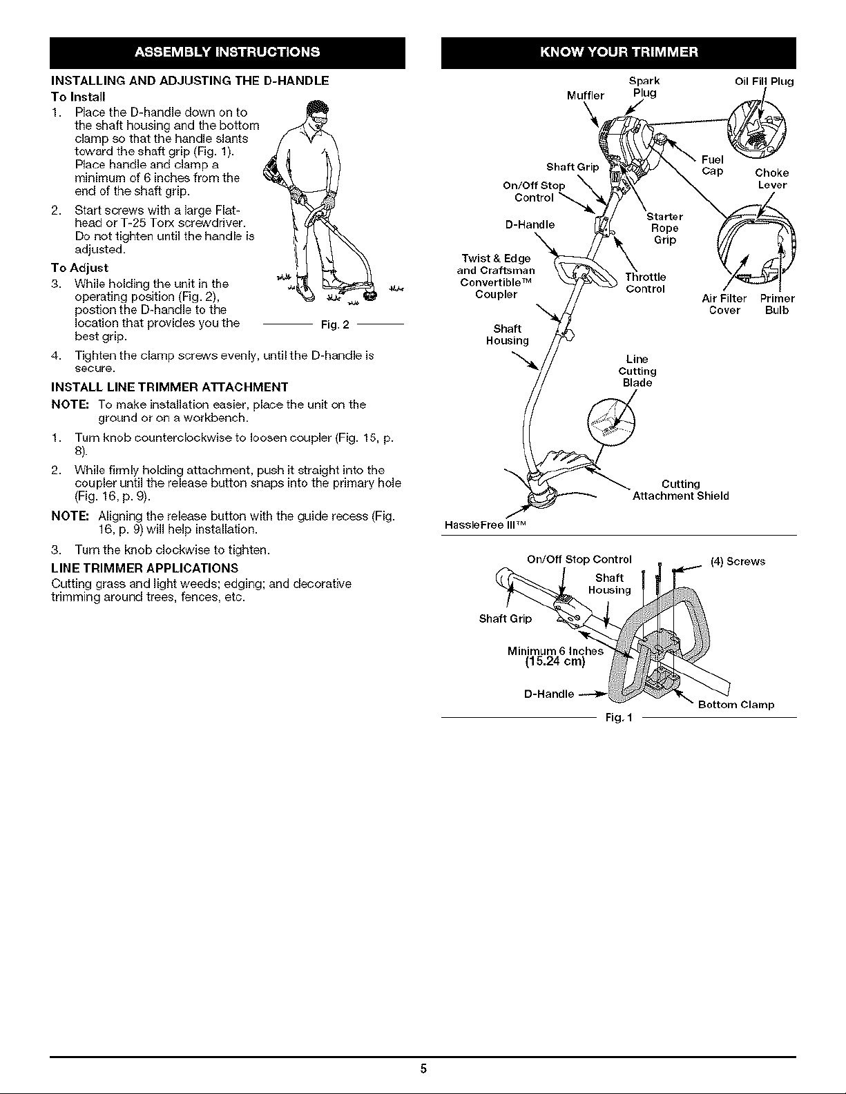
INSTALLING AND ADJUSTING THE D-HANDLE
To Install
Place the D-handle down on to
the shaft housing and the boffom
clamp so that the handle slants
toward the shaft grip (Fig. I).
Place handleand clamp a
minimum of 6 inches from the
end of the shaft grip.
2. Start screws with a large Flat-
head or T-25 Torx screwdriver.
Do not tighten until the handle is
adjusted.
To Adjust
3. While holding the unit in the
operating position (Fig. 2),
postion the D-handle to the
location that provides you the
Fig. 2
best grip.
4.
Tighten the clamp screws evenly, until the D-handle is
secure.
INSTALL LINE TRIMMER ATTACHMENT
NOTE: To make installation easier, place the unit on the
ground or on a workbench.
1. Turn knob counterclockwise to loosen coupler (Fig. 15, p.
8).
2. While firmly holding attachment, push it straight into the
coupler until the release button snaps into the primary hole
(Fig. 16, p. 9J.
NOTE: Aligning the release button with the guide recess (Fig.
16, p. 9)will help installation.
3. Turn the knob clockwise to tighten.
LINE TRIMMER APPLICATIONS
Cutting grass and light weeds; edging; and decorative
tdmming around trees, fences, etc.
4L_
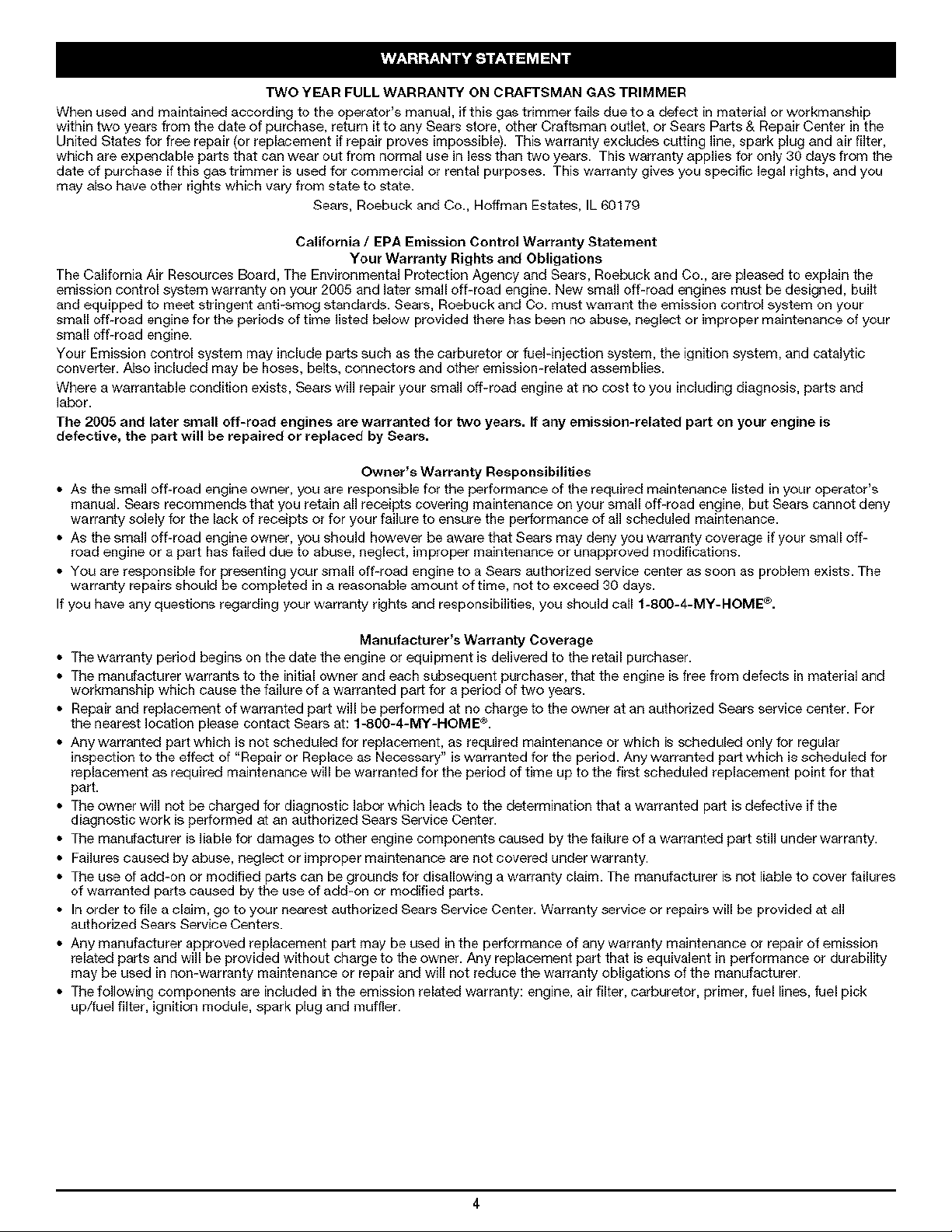
Spark Oil Fill Plug
Muffler _._ug [
Shaft Grip Cap Choke
On/Off Stop Lever
Control .P._X'_ _ _P Czk_
D-Handle Rope
Grip
Twist & Edge
Convertible TM I Throttle
Couple// Air Filter Primer
_ X 'S tartSI_:_r_l_r
Cover Bulb
Shaft
Housing
Line
Cutting
Blade
_A Cutting
ttachment Shield
HassleFree IIF M
On/Off Stop Control
Shaft
Housing
Shaft Grip
(4) Screws
Minimum 6 Inoh_
(15.24 ore)
D-Handle
Fig, 1
_rl WARNING: OVERFILLING OIL CRANKCASE MAY
maintain the proper oil level in the crank case; it is
important and cannot be overemphasized. Check
I I SeetheOiIohanqinqbeforeeachtheoilUseand change it as needed. I
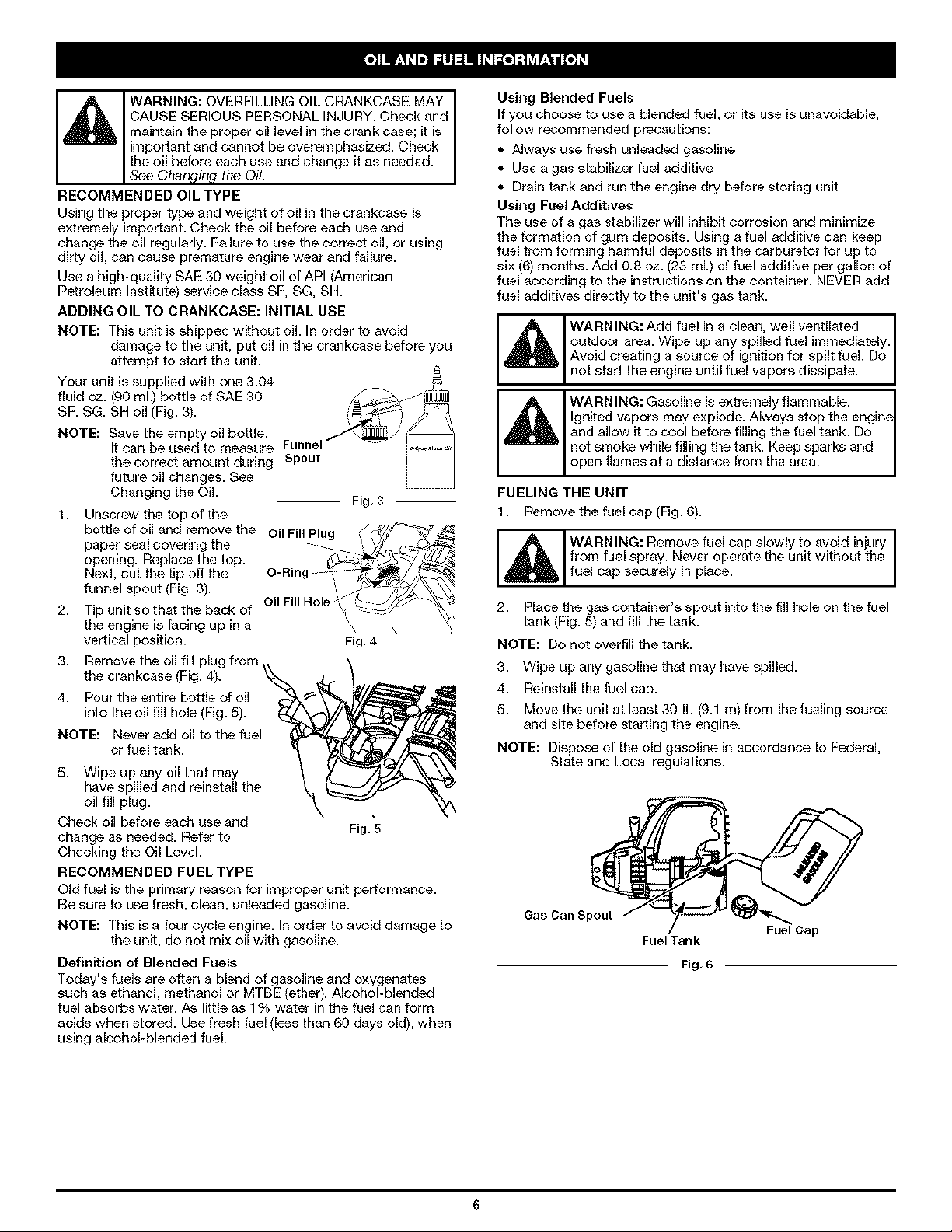
RECOMMENDED OIL TYPE
Using the proper type and weight of oil in the crankcase is
extremely important. Check the oil before each use and
change the oil regularly. Failure to use the correct oil, or using
dirty oil, can cause premature engine wear and failure.
Use a high-quality SAE 30 weight oil of API (American
Petroleum Institute) service class SF, SG, SH.
ADDING OIL TO CRANKCASE: INITIAL USE
NOTE: This unit is shipped without oil. In order to avoid
damage to the unit, put oil in the crankcase before you
attempt to start the unit.
Your unit issupplied with one 3.04
fluid oz. (90 ml.) bottle of SAE 30 _.---- _
SF, SG, SH oil (Fig. 3). _ _;_ _ I,
_'..,-Zr_J'f I,
CAUSE SERIOUS PERSONAL INJURY. Check and
NOTE: Save the empty oil bottle. _ \_,_/ _
1. Unscrew the top of the
2. Tip unit so that the back of
3. Remove the oil fill plug from
4. Pour the entire bottle of oil
NOTE: Never add oil to the fuel
5. Wipe up any oil that may
Check oil before each use and Fig. 5
change as needed. Refer to
Checking the Oil Level.
RECOMMENDED FUEL TYPE
Old fuel is the primary reason for improper unit performance.
Be sure to use fresh, clean, unleaded gasoline.
NOTE: This is a four cycle engine. In order to avoid damage to
Definition of Blended Fuels
Today's fuels are often a blend of gasoline and oxygenates
such as ethanol, methanol or MTBE (ether). AIcohobblended
fuel absorbs water. As little as 1% water in the fuel can form
acids when stored. Use fresh fuel (less than 60 days old), when
using alcohol-blended fuel.
It can be used to measure Funnel i_,_,_.,_,_,
the correct amount during Spout i
future oil changes. See =
Changing the OiL Fig, 3
bottle of oil and remove the
paper seal covering the
opening. Replace the top.
Next, cut the tip off the
funnel spout (Fig. 3).
the engine is facing up in a
vertical position. Fig,4
the crankcase (Fig. 4).
into the oil fill hole (Fig. 5).
or fuel tank.
have spilled and reinstall the
oil fill plug.
the unit, do not mix oil with gasoline.
Using Blended Fuels
Ifyou choose to use a blended fuel, or its use is unavoidable,
follow recommended precautions:
• Always use fresh unleaded gasoline
• Use a gas slabilizer fuel additive
• Drain tank and run the engine dry before storing unit
Using Fuel Additives
The use of a gas stabilizer will inhibit corrosion and minimize
the formation of gum deposffs. Using a fuel additive can keep
fuel from forming harmful deposits in the carburetor for up to
six (6) months. Add 0.8 oz. (23 mL) of fuel additive per gallon of
fuel according to the instructions on the container. NFVER add
fuel additives directly to the unit's gas tank.
WARNING: Add fuel in a clean, well ventilated
outdoor area. Wipe up any spilled fuel immediately.
Avoid of for fuel Do
creating a source ignition spilt
not start the engine until fuel vapors dissipate.
WARNING: Gasoline is extremely flammable.
Ignited vapors may explode. Always stop the engin_
_ and allow g to cool before filling the fuel tank. Do
not smoke while filling the tank. Keep sparks and
open flames at a distance from the area.
FUELING THE UNIT
1. Remove the fuel ca R(Fig. 6).
WARNING: Remove fuel cap slowly to avoid injury
from fuel spray. Never operate the unit without the
fuel cap securely in place.
2. Place the gas container's spout into the fill hole on the fuel
tank (Fig. 5) and fill the tank.
NOTE: Do not overfill thetank.
3. Wipe up any gasoline that may have spilled.
4. Reinstall the fuel ca R.
5. Move the unit at least 30 ft. (9.1 m) from the fueling source
and site before starting the engine.
NOTE: Dispose of the old gasoline in accordance to Federal,
State and Local regulations.
Gas Can Spout
Fuel Tank
Fig, 6
Fuel Cap
WARNING: Operate this unit only in a well-
ventilated outdoor area. Carbon monoxide exhaust
fumes can be lethal in a confined area.
WARNING: Avoid accidental starting. Make sure
you are inthe starting position when pulling the
starter rope (Fig. 8). To avoid serious injury, the
operator and un t must be n a stab epos t on wh e
starting.
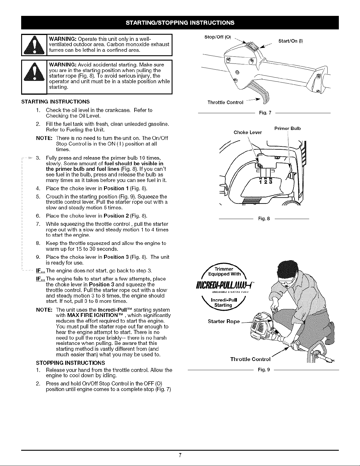
Stop/Off (O) .
Start/On (I)
STARTING INSTRUCTIONS
1. Checktheoillevelinthecrankcase. Referto
Checking the Oil Level.
2. Fill the fuel tank with fresh, clean unleaded gasoline.
Refer to Fueling the Unit.
NOTE: There is no need to turn the unit on. The On/Off
Stop Control is in the ON ( I ) position at all
times.
3. Fully press and release the primer bulb 10 times,
slowly. Some amount of fuel should be visible in
the primer bulb and fuel lines (Fig. 8). If you can't
see fuel in the bulb. press and release the bulb as
many times as it takes before you can see fuel in it.
4. Place the choke lever in Position f (Fig. 8).
5. Crouch in the starting posNon (Fig. 9). Squeeze the
throttle control lever. Pull the starter rope out with a
slot, and steady motion 5 times.
6. Place the choke lever in Position 2 (Fig. 8).
7. While squeezing the throttle control, pull the starter
rope out with a slot, and steady motion 1 to 4 times
to start the engine.
8. Keep the throttle squeezed and allow the engine to
warm up for 15 to 30 seconds.
9. Place the choke lever in Position 3 (Fig. 8). The unit
is ready for use.
IF-. The engine does not start, go back to step 3.
IF-. The engine fails to start after a few attempts, place
the choke lever in Position 3 and squeeze the
throttle control. Pull the starter rope out with a slot,
and steady motion 3 to 8 times, the engine should
start. If not. pull 3 to 8 more times.
NOTE: The unit uses the Incredi-RuIP Mstarting system
with MAX FIRE IGNITION TM . which significantly
reduces the effort required to start the engine.
You must pull the starter rope out far enough to
hear the engine attempt to start. There is no
need to pull the rope briskly-- there is no harsh
resistance when pulling. Be aware that this
starting method is vastly different from (and
much easier than) what you may be used to.
STOPPING INSTRUCTIONS
1. Release your hand from the throttle control. Allow the
engine to cool down by idling.
2. Press and hold On/Off Stop Control in the OFF (0)
position until engine comes to a complete stop (Fig. 7)
Throttle Control
OhokeLever
Throttle Control
Fig, 7
Primer Bulb
Fig. 8
Fig, 9
WARNING: AM,ays wear eye, hearing, foot and
body protection to reduce the risk of in ury when
operating this unit.
HOLDING THE TRIMMER
Before operating the unit, stand in the operating position (Fig.
10). Check for the following:
• The operator is wearing eye protection and proper clothing
• With a slightly-bent right arm, the operator's right hand is
holding the shaft grip
• The operator's left arm is straight, the left hand holding the
assist handle
• The unit is at waist level
• The cutting attachment is parallel to the ground and easily
contacts the grass without the need to bend over
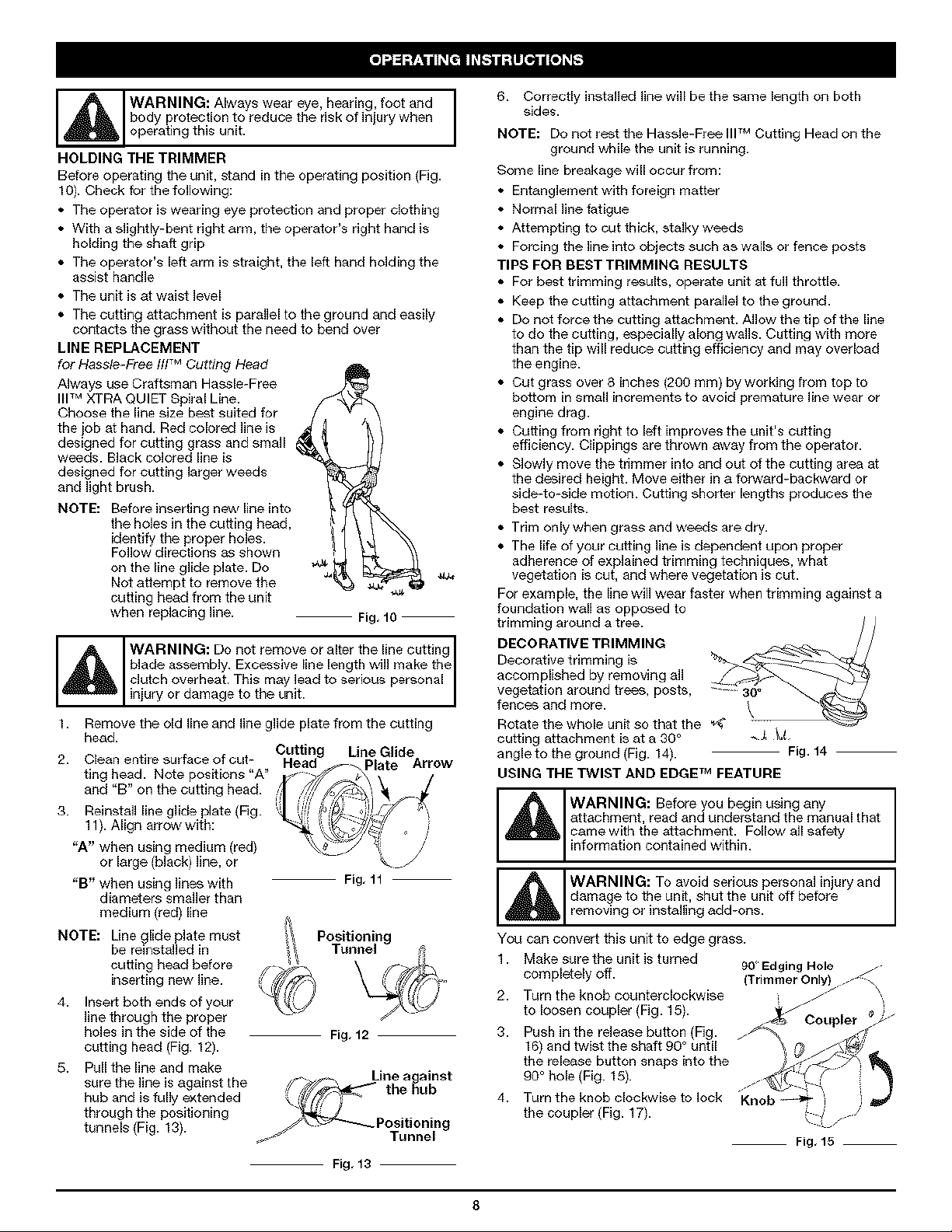
LINE REPLACEMENT
for Hassle-Free flffM Cutting Head
Always use Craftsman Hassle-Free
lip MXTRA QUIFT Spiral Line.
Choose the line size best suited for
the job at hand. Red colored line is
designed for cutting grass and small
weeds. Black colored line is
designed for cutting larger weeds
and light brush.
NOTE: Before inserting new line into
the holes in the cutting head,
identify the proper holes.
Follow directions as shown
on the line glide plate. Do
Not attempt to remove the
cutting head from the unit
when replacing line. Fig, 10
blade assembly. Excessive line length will make the
WARNING: Do not remove or alter the line cutting
clutch overheat. This may lead to serious personal
injury or damage to the unit.
1. Remove the old line and line glide plate from the cutting
head.
2. Clean entire surface of cut-
ting head. Note posffions "A"
and "B" on the cutting head.
3. Reinstall line glide plate (Fig.
11). Align arrow with:
"A" when using medium (red)
or large (black) line, or
"B" when using lines with
Fig, 11
diameters smaller than
medium (red) line
NOTE: Line glide plate must
be reinstalled in
Positioning
Tunnel
cutting head before
inserting new line.
4. Insert both ends of your
line through the proper
holes in the side of the
Fig, 12
cutting head (Fig. 12).
5. Pull the line and make
sure the line is against the ,_'Y_ the _ub
Line a ainst
hub and is fully extended ,_j,
through the positioning
tunnels (Fig. 13). _* --P°siti°ning
_* Tunnel
Fig, 13
6. Correctly instelled linewilI be the same length on both
sides.
NOTE: Do not rest the Hassle-Free IIPM Cutting Head on the
ground while the unit is running.
Some line breakage will occur from:
• Entanglement with foreign matter
• Normal line fatigue
• Attempting to cut thick, atalky weeds
• Forcing the line into objects such as walls or fence posts
TIPS FOR BEST TRIMMING RESULTS
• For best trimming results, operate unit at full throttle.
• Keep the cutting attachment parallel to the ground.
• Do not force the cutting attachment. Allow the tip of the line
to do the cutting, especially along walls. Cutting with more
than the tip will reduce cutting efficiency and may overload
the engine.
• Cut grass over 8 inches (200 mm) by working from top to
bottom in small increments to avoid premature line wear or
engine drag.
• Cutting from right to left improves the unit's cutting
efficiency. Clippings are thrown away from the operator.
• Slowly move the trimmer into and out of the cutting area at
the desired height. Move either in afonA, ard-backward or
side-to-side motion. Cutting shorter lengths produces the
best results.
• Trim only when grass and weeds are dry.
• The life of your cutting line is dependent upon proper
adherence of explained trimming techniques, what
vegatation is cut, and where vegetation is cut.
For exam pie, the line will wear faster when trimming against a
foundation wall as opposed to
trimming around a tree. / /
DECORATIVE TRIMMING
Decorative trimming is
accomplished by removing all
vegetation around trees, posts, _-- 30_
fences and more.
Rotate the whole unit so that the
cutting attachment is at a 30° _ _,
angle to the ground (Fig. 14). Fig. 14
USING THE TWIST AND EDGE TM FEATURE
WARNING: Before you begin using any
_l_ attachment, read and understand the manual that
came with the attachment. Follow all safety
information contained within.
damage to the unff, shut the unit off before
I _l WARNING: To avoid serious personal injury and
removing or instellingadd-ons.
You can convert this unit to edge grass.
1. Make sure the unit is turned
completely off.
90' Edging Hole _
Trimmer Only .-_
2. Turn the knob counterclockwise
to loosen coupler (Fig. 15).
_/Coupler
g. Push in the release button (Fig.
16) and twist the shaft 90° until
the release button snaps into the
90 ° hole (Fig. 15).
4. Turn the knob clockwise to lock
the coupler (Fig. 17).
Fig, 15
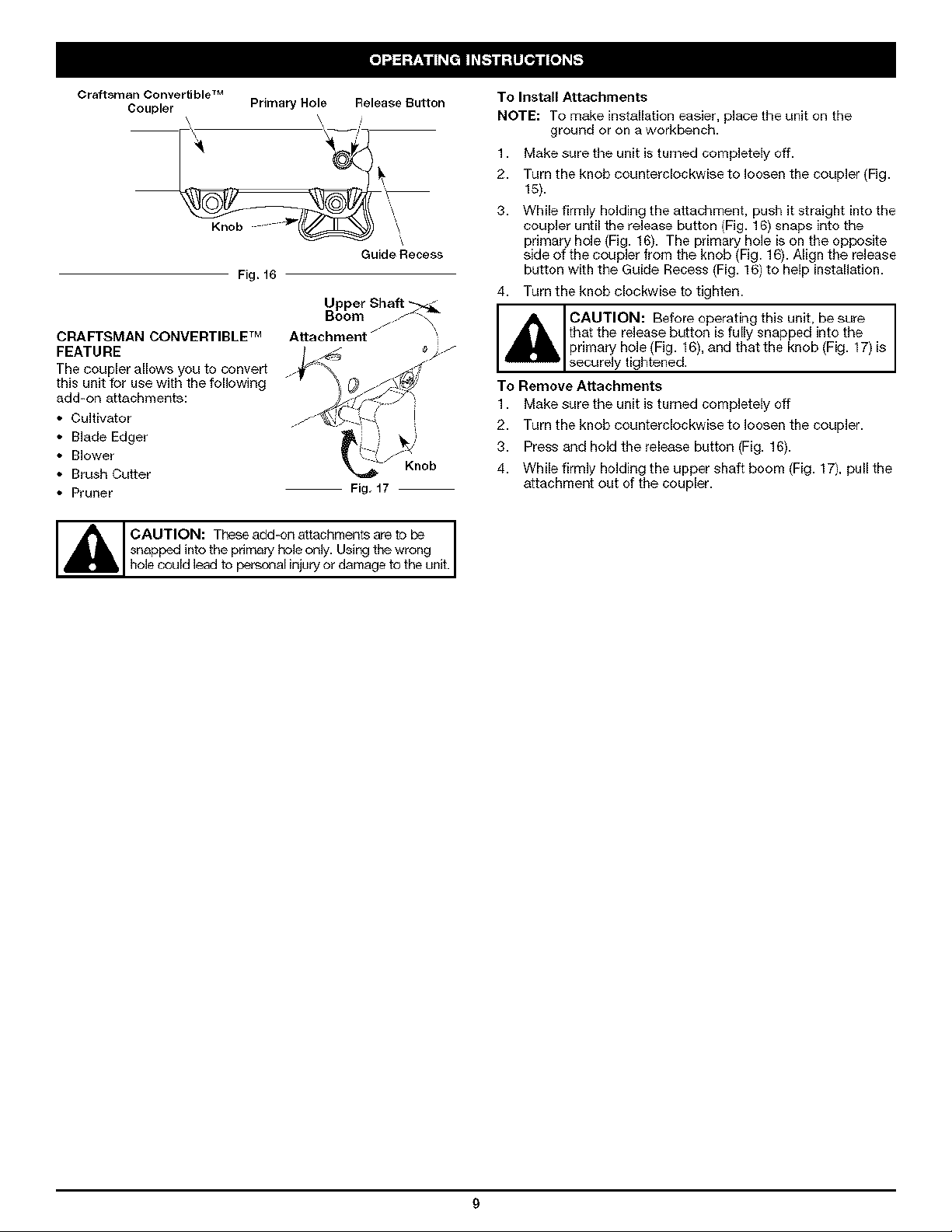
Craftsman Convertible TM
Coupler
Primary Hole Release Button
Knob _ _ _ \
GuideRecess
Fig. 16
Upper Shaft
To Install Attachments
NOTE: To make installation easier, place the unit on the
ground or on a workbench.
1. Make sure the unit is turned completely off.
2. Turn the knob counterclockwise to loosen the coupler (Fig.
15).
g. While firmly holding the attachment, push it straight into the
coupler until the release button (Fig. 16) snaps into the
primary hole (Fig. 16). The primary hole is on the opposite
side of the coupler from the knob (Fig. 16). Align the release
buffon with the Guide Recess (Fig. 16) to help installation.
4. Turn the knob clockwise to tighten.
CRAFTSMAN CONVERTIBLE TM
FEATURE
The coupler allows you to convert
this unit for use with the following
add-on attachments:
• Cugivator
• Blade Edger
• Blower
• Brush Cutter
• Pruner
hole could lead o personal injuryor damage o he uni.
Attachment /
Fig, 17
Knob
_ AUTION: Before operating this unit, be sure
that the release button is fully snapped into the
primary hole (Fig. 16), and that the knob (Fig. 17) is
secure y t ghtened.
To Remove Attachments
1. Make sure the unit is turned completely off
2. Turn the knob counterclockwise to loosen the coupler.
g. Press and hold the release button (Fig. 16).
4. While firmly holding the upper shaft boom (Fig. 17), pull the
attachment out of the coupler.
NOTE: Maintenance, replacement, or repair of the emission
performmaintenanceorrepairswithunitrunning.
WARNING:Topreventseriousinjury,never
Alwaysserviceandrepairacoolunit.Disconnectthe
sparkpugwretoensurethattheunt cannotstart.
MAINTENANCE SCHEDULE
Perform these required maintenance procedures at the
frequency stated in the table. These procedures should also
be a part of any seasonal tune-up.
NOTE: Some maintenance procedures may require special
tools or skills. If you are unsure about these
procedures take your unit to a Sears or other qualified
service dealer.
FREQUENCY MAINTENANCE REQUIRED BEE
In order to assure peak performance of your engine, inspection
of the engine exhaust port may be necessary after 50 hours of
operation. If you notice lost RPM, poor performance or general
lack of acceleration, this service may be required. If you feel
your engine is in need of this inspection, refer service to a
Sears or other qualified service dealer for repair. DO NOT
attempt to perform this process yourself as engine damage
may result from contaminants involved in the cleaning process
for the port.
control devices and system may be performed by a
Sears or other qualified service dealer.
Before starting engine Check oil p. 10
Fvery 10 hours Clean and re-oil air filter p. 11
1st change at 10 hours Change oil p. 10
2nd change at 25 hours Change oil p. 10
Fvery 25 hours after Clean spark arrestor p. 13
10 hours on new engine Check rocker arm to valve clearance and adjust p. 12
Every 25 hours Check rocker arm to valve clearance and adjust p. 12
Fvery 25 hours Check spark plug condition and gap p. 13
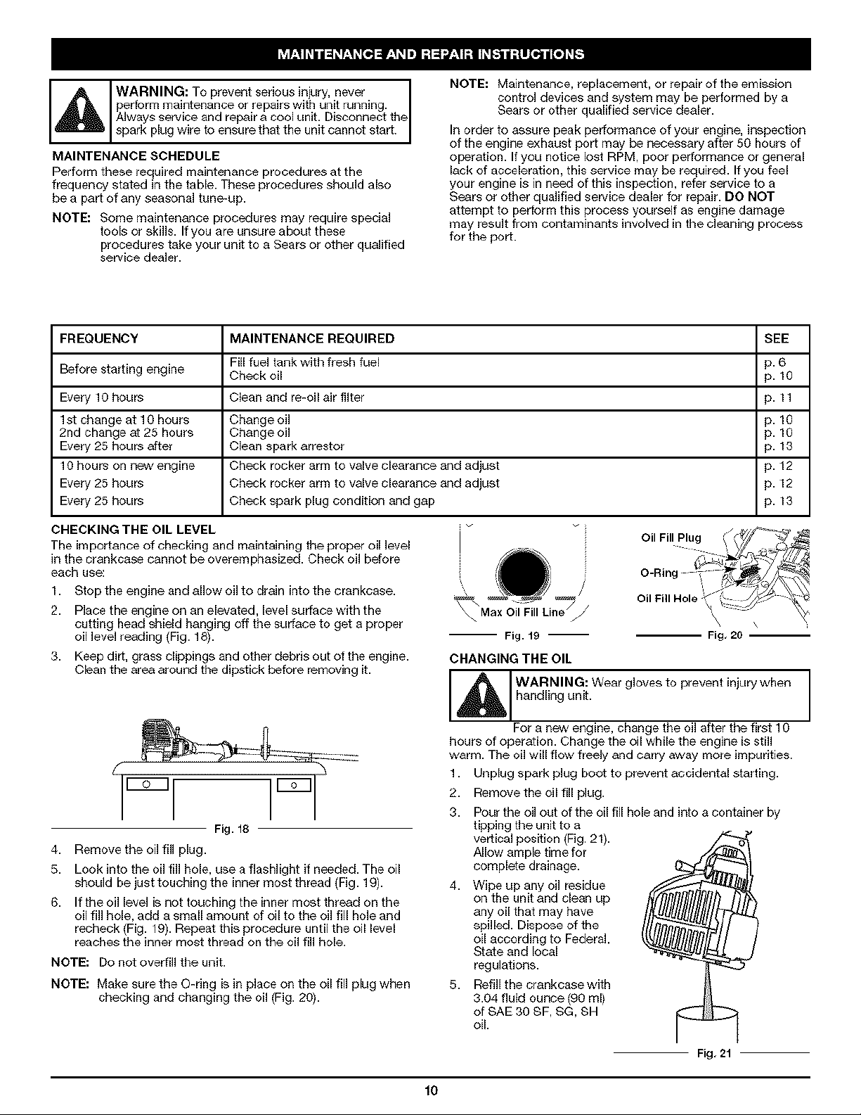
CHECKING THE OIL LEVEL
The importance of checking and maintaining the proper oil level
in the crankcase cannot be overemphasized. Check oil before
each use:
1. Stop the engine and allow oil to drain into the crankcase.
2. Place the engine on an elevated, level surface with the
cutting head shield hanging off the surface to get a proper
oil level reading (Fig. 18).
3. Keep dirt, grass clippings and other debris out of the engine.
Clean the area around the dipstick before removing it.
Fill fuel tank with fresh fuel p. 6
\ \ Max Oil Fill Line
-- Fig. 19 --
CHANGING THE OIL
Fig, 20
Wearg,ovestoprevent,njurywhen
For a new engine, change the oil after the first 10
hours of operation. Change the oil while the engine isstill
warm. The oil will flow freely and carry away more impurities.
1. Unplug spark plug boot to prevent accidental starting.
2. Remove the oil fill plug.
g. Pour the oil out of the oil fill hole and into a container by
Fig. 18
4. Remove the oil fill plug.
5. Look into the oil fill hole, use a flashlight if needed. The oil
should be just touching the inner most thread (Fig. 19).
6. If the oil level is not touching the inner most thread on the
oil fill hole, add a small amount of oil to the oil fill hole and
recheck (Fig. 19). Repeat this procedure until the oil level
reaches the inner most thread on the oil fill hole.
NOTE: Do not overfill the unit.
NOTE: Make sure the O-ring is in place on the oil fill plug when
checking and changing the oil (Fig. 20).
tipping the unit to a
vertical posffion (Fig. 21).
Allow ample time for
complete drainage.
4. Wipe up any oil residue
on the unit and clean up
any oil that may have
spilled. Dispose of the
oil according to Federal,
State and local
regulations.
5. Refill the crankcase with
3.04 fluid ounce (90 ml)
of SAE 30 SF, SG, BH
oil.
Fig, 21
f0
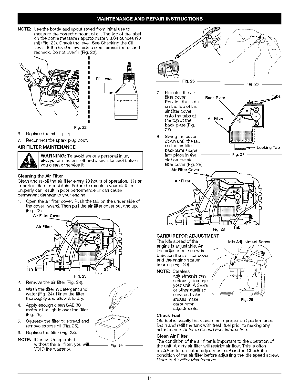
NOTE:Usethebottleandspout saved from initial use to
measure the correct amount of oil. The top of the label
on the bottle measures approximately 3.04 ounces (90
ml) {Fig. 22). Check the level, See Checking the Oil
Level. If the level is low, add a small amount of oil and
recheck. Do not overfill {Fig. 22).
\ FilI L__
Fig. 22
6. Replacethe oil fill plug.
7. Reconnect the spark plug boot.
AIR FILTER MAINTENANCE
WARNING: To avoid serious personal injury,
always turn the unit off and allow it to cool before
you clean or service it.
Cleaning the Air Filter
Clean and re-oil the air filter every 10 hours of operation. It is an
important item to maintain. Failu_ to maintain your air filter
properly can result in poor performance or can cause
permanent damage to your engine.
1. Open the air filter cover. Push the tab on the under side of
the cover inward. Then pull the air filter cover out and up.
(Fig. 23).
Fig. 25
7. Reinstall the air
filter cover.
Position the slots
on the top of the
air filter cover
onto the tabs at
the top of the
back plate (Fig.
27).
8. Swing the cover
down until the tab
on the air filter
backplate snaps
into place in the
slot on the air
filter cover (Fig. 28).
Air Filter Cover
Back Plate
J
Fig. 27
I
! j
/
Fig. 26
Tabs
Looking Tab
Fig. 23
2. Removethe air filter (Fig. 23).
3. Wash the filter in detergent and
water (Fig. 24). Rinse the filter
thoroughly and allow it to dry.
4. Apply enough clean SAE 30
motor oil to lightly coat the filter
(Fig. 25).
5. Squeeze the filter to spread and
remove excess oil (Fig. 26).
6. Replace the filter (Fig. 23).
NOTE: If the unit Jsoperated
without the air filter, you will Fig. 24
VOID the warranty.
Tab
Fig, 28 Tab
CARBURETOR ADJUSTMENT
The idle speed of the Id]e Adjustment Screw
engine is adjustable. Aq
idle adjustment screw is
between the air filter cover
and the engine starter
housing (Fig. 29).
NOTE: Careless
adjustments can
seriously damage
your unit. A Sears
or other qualified
service dealer
should make Fig. 29
carburetor
adjustments.
Check Fuel
Old fuel is usually the reason for improper unit performance.
Drain and refill the tank with fresh fuel prior to making any
adjustments. Refer to Oil and Fuel Informagon,
Clean Air Filter
The condition of the air filter is important to the operation of
the unit. A dirty air filter will restrict air flow. This is often
mistaken for an out of adjustment carburetor. Check the
condition of the air filter before adjusting the idle speed screw.
Refer to Air Filter Maintenar}ce,
11
 Loading...