

Craftsman 316.794831 Operator's Manual

Operator's Manual
4-Cycle
HANDHELD BLOWER
Model No. 316.794831
INCREDI.PULL) LH
UNBELIEVABLE STARTING E A S E
• SAFETY
• ASSEMBLY
• OPERATION
• MAINTENANCE
• PARTS LIST
• ESPANOL, P. 11
CAUTION: Before using this
product, read this manual and
understand all safety rules and
operating instructions.
Sears Brand Management Corporation, Hoffman Estates, IL 60179, U.S.A.
Visit our website: www.craftsman.com
769-06546 P00 10/10
CALIFORNIA PROPOSITION 65
THE ENGINE EXHAUST FROM THIS PRODUCT CONTAINS CHEMICALS
KNOWN TO THE STATE OF CALIFORNIA TO CAUSE CANCER, BIRTH
TABLE OF CONTENTS
Safety Rules .................................................................................................... 2
Warranty .......................................................................................................... 4
Know Your Unit ............................................................................................... 4
Assembly Instructions ..................................................................................... 4
Oil and Fuel Information .................................................................................. 5
Starting/Stopping Instructions ........................................................................ 5
Operating Instructions .................................................................................... 6
Maintenance and Repair Instructions ............................................................. 6
Cleaning and Storage ..................................................................................... 8
Troubleshooting Chart ..................................................................................... 8
Specifications ................................................................................................. 9
Parts List ....................................................................................................... 30
Service Numbers ........................................................................... Back Cover
SPARK ARRESTOR NOTE
NOTE: For users on U.S. Forest Land and in the states of California, Maine,
Oregon and Washington. All U.S. Forest Land and the state of California
(Public Resources Codes 4442 and 4443), Oregon and Washington require, by
law that certain internal combustion engines operated on forest brush and/or
grass-covered areas be equipped with a spark arrestor, maintained in effective
working order, or the engine be constructed, equipped and maintained for the
prevention of fire. Check with your state or local authorities for regulations
pertaining to these requirements. Failure to follow these requirements could
subject you to liability or a fine. This unit is factory equipped with a spark
arrestor. If it requires replacement, ask your LOCAL SERVICE DEALER to
install the Accessory Part #753-05900 Muffler Assembly
DEFECTS OR OTHER REPRODUCTIVE HARM
he purpose of safety symbols is to attract your attention to possible dangers.J
he safety symbols, and their explanations, deserve your careful attentionJ
nd understanding. The safety warnings do not by themselves eliminate any_
anger. The instructions or warnings they give are not substitutes for proper 1
ccident prevention measures. |
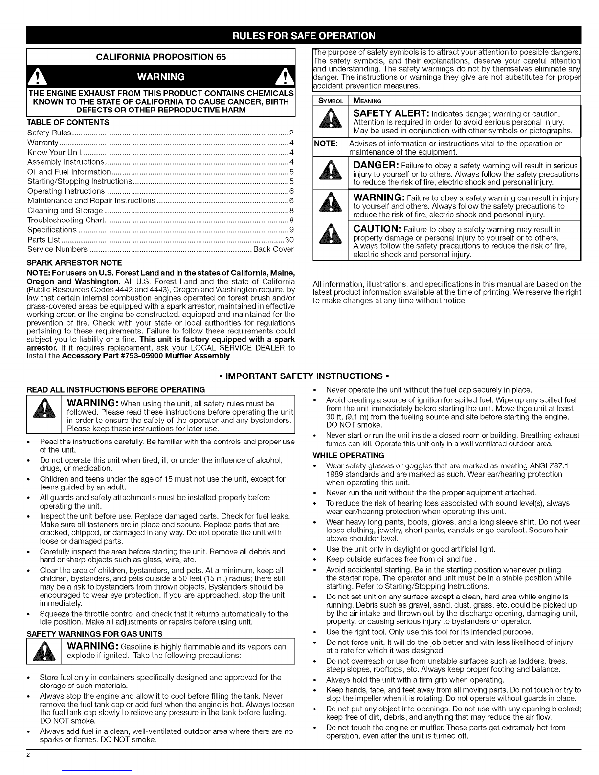
SYMBOL MEANING
SAFETY ALERT: Indicates danger, warning or caution.
Attention is required in order to avoid serious personal injury.
May be used in conjunction with other symbols or pictographs.
NOTE: Advises of information or instructions vital to the operation or
All information, illustrations, and specifications in this manual are based on the
latest product information available at the time of printing. We reserve the right
to make changes at any time without notice.
maintenance of the equipment.
DANGER: Failure to obey a safety warning will result in serious
injury to yourself or to others. Always follow the safety precautions
to reduce the risk of fire, electric shock and personal injury.
WARNING: Failure to obey a safety warning can result in injury
to yourself and others. Always follow the safety precautions to
reduce the risk of fire, electric shock and personal injury.
CAUTION: Failure to obey a safety warning may result in
property damage or personal injury to yourself or to others.
Always follow the safety precautions to reduce the risk of fire,
electric shock and personal injury.
• IMPORTANT SAFETY INSTRUCTIONS •
READ ALL INSTRUCTIONS BEFORE OPERATING
_IL WARNING: When using the unit, all safety rules must be J
• Read the instructions carefully. Be familiar with the controls and proper use
• Do not operate this unit when tired, ill, or under the influence of alcohol,
• Children and teens under the age of 15 must not use the unit, except for
• All guards and safety attachments must be installed properly before
• Inspect the unit before use. Replace damaged parts. Check for fuel leaks.
• Carefully inspect the area before starting the unit. Remove all debris and
• Clear the area of children, bystanders, and pets. At a minimum, keep all
• Squeeze the throttle control and check that it returns automatically to the
SAFETY WARNINGS FOR GAS UNITS
• Store fuel only in containers specifically designed and approved for the
• Always stop the engine and allow it to cool before filling the tank. Never
• Always add fuel in a clean, well-ventilated outdoor area where there are no
followed. Please read these instructions before operating the unit
n order to ensure the safety of the operator and any bystanders.
Please keep these instructions for later use.
of the unit.
drugs, or medication.
teens guided by an adult.
operating the unit.
Make sure all fasteners are in place and secure. Replace parts that are
cracked, chipped, or damaged in any way. Do not operate the unit with
loose or damaged parts.
hard or sharp objects such as glass, wire, etc.
children, bystanders, and pets outside a 50 feet (15 m.) radius; there still
may be a risk to bystanders from thrown objects. Bystanders should be
encouraged to wear eye protection. If you are approached, stop the unit
immediately.
idle position. Make all adjustments or repairs before using unit.
WARNING: Gasoline is highly flammable and its vapors can
explode if ignited. Take the following precautions:
storage of such materials.
remove the fuel tank cap or add fuel when the engine is hot. Always loosen
the fuel tank cap slowly to relieve any pressure inthe tank before fueling.
DO NOT smoke.
sparks or flames. DO NOT smoke.
• Never operate the unit without the fuel cap securely in place.
• Avoid creating a source of ignition for spilled fuel. Wipe up any spilled fuel
from the unit immediately before starting the unit. Move thge unit at least
30 ft. (9.1 m) from the fueling source and site before starting the engine.
DO NOT smoke.
• Never start or run the unit inside a closed room or building. Breathing exhaust
fumes can kill. Operate this unit only in a well ventilated outdoor area.
WHILE OPERATING
• Wear safety glasses or goggles that are marked as meeting ANSI Z87.1-
1989 standards and are marked as such. Wear ear/hearing protection
when operating this unit.
• Never run the unit without the the proper equipment attached.
• To reduce the risk of hearing loss associated with sound level(s), always
wear ear/hearing protection when operating this unit.
• Wear heaw long pants, boots, gloves, and a long sleeve shirt. Do not wear
loose clothing, jewelry, short pants, sandals or go barefoot. Secure hair
above shoulder level.
• Use the unit only in daylight or good artificial light.
• Keep outside surfaces free from oil and fuel.
• Avoid accidental starting. Be in the starting position whenever pulling
the starter rope. The operator and unit must be in a stable position while
starting. Refer to Starting/Stopping Instructions.
• Do not set unit on any surface except a clean, hard area while engine is
running. Debris such as gravel, sand, dust, grass, etc. could be picked up
by the air intake and thrown out by the discharge opening, damaging unit,
property, or causing serious injury to bystanders or operator.
• Use the right tool. Only use this tool for its intended purpose.
• Do not force unit. It will do the job better and with less likelihood of injury
at a rate for which it was designed.
• Do not overreach or use from unstable surfaces such as ladders, trees,
steep slopes, rooftops, etc. Always keep proper footing and balance.
• Always hold the unit with a firm grip when operating.
• Keep hands, face, and feet away from all moving parts. Do not touch or try to
stop the impeller when it is rotating. Do not operate without guards in place.
• Do not put any object into openings. Do not use with any opening blocked;
keep free of dirt, debris, and anything that may reduce the air flow.
• Do not touch the engine or muffler. These parts get extremely hot from
operation, even after the unit is turned off.
• Donotoperatetheenginefasterthanthespeedneededtodothejob.Do
notruntheengineathighspeedwhennotinuse.
• Alwaysstoptheenginewhenoperationisdelayedorwhenwalkingfrom
onelocationtoanother.
• Stoptheengineformaintenance,repair,toinstallorremovetheblower
tubes.Theunitmustbestoppedandtheimpellernolongerturningto
avoidcontactwiththerotatingblades.
• Ifyoustrikeorcomeintocontactwithaforeignobject,stoptheengine
immediatelyandcheckfordamage.Donotoperatebeforerepairing
damage.Donotoperatetheunitwithlooseordamagedparts.
• Useonlygenuinefactoryreplacementpartsandaccessoriesforthis
unit.Theseareavailablefromyourauthorizedservicedealer.Useofany
unauthorizedpartsoraccessoriescouldleadtoseriousinjurytotheuser
ordamagetotheunit,andvoidyourwarranty.
• Toreducefirehazard,replacefaultymufflerandsparkarrestor.Keepthe
engineandmufflerfreefromgrass,leaves,excessivegreaseorcarbon
buildup.
• Neverpointtheblowerinthedirectionofbystanders,animals,windowsor
automobiles.
OTHERSAFETYWARNINGS
• Neverstoretheunit,withfuelinthetank,insideabuildingwherefumes
mayreachanopenflame(pilotlights,etc.)orsparks(switches,electrical
• Allowtheenginetocoolbeforestoringortransporting.Besuretosecure
theunitwhiletransporting.
• Storetheunitinadryplace,eitherlockeduporuphightoprevent
unauthorizeduseordamage.Keepoutofthereachofchildren.
• Neverdouseorsquirttheunitwithwateroranyotherliquid.Keephandles
dry,clean,andfreefromdebris.Cleanaftereachuse,seeCleaningand
Storageinstructions.
• Keeptheseinstructions.Refertothemoftenandusethemtoinstructother
users.Ifyouloanthisunittoothers,alsoloantheseinstructionstothem.
SPECIAL NOTE: EXPOSURE TO VIBRATIONS THROUGH PROLONGED
USE OF GASOLINE POWERED HAND TOOLS COULD CAUSE
BLOOD VESSEL OR NERVE DAMAGE IN THE FINGERS, HANDS,
AND JOINTS OF PEOPLE PRONE TO CIRCULATION DISORDERS
OR ABNORMAL SWELLING. Prolonged use in cold weather has
been linked to blood vessel damage in otherwise healthy people. If
symptoms occur such as numbness, pain, loss of strength, change
in skin color or texture, or loss of feeling in the fingers, hands or
joints, discontinue use of this tool and seek medical attention.
An anti-vibration system does not guarantee avoidance of these
problems. Users who operate power tools on a regular basis must
closely monitor their physical condition and the condition of this tool.
SAVE THESE INSTRUCTIONS
motors,etc.).
• SAFETY & INTERNATIONAL SYMBOLS •
This operator's manual describes safety and international symbols and pictographs that may appear on this product. Read the operator's manual for complete
safety, assembly, operating and maintenance and repair information.
SYMBOL MEANING SYMBOL MEANING
CRAFTSMAN 2 YEAR FULL WARRANTY
FOR 2 YEAR(S) from the date of purchase, this product is warranted against any defects in material or workmanship. Defective product will receive free repair
or free replacement if repair is unavailable.
For warranty coverage details to obtain repair or replacement, visit the web site: www.craftsman.com
This warranty covers ONLY defects in material and workmanship. Warranty coverage does NOT include:
• Expendable items that can wear out from normal use within the warranty period, such as air cleaner or spark plug.
• Product damage resulting from user attempts at product modification or repair or caused by product accessories.
• Repairs necessary because of accident or failure to operate or maintain the product according to all supplied instructions.
• Preventive maintenance, or repairs necessary due to improper fuel mixture, contaminated or stale fuel.
This warranty is void if this product is ever used while providing commercial services or if rented to another person. This warranty gives you specific legal
rights, and you may also have other rights which vary from state to state.
Sears Brands Management Corporation, Hoffman Estates, IL 60179
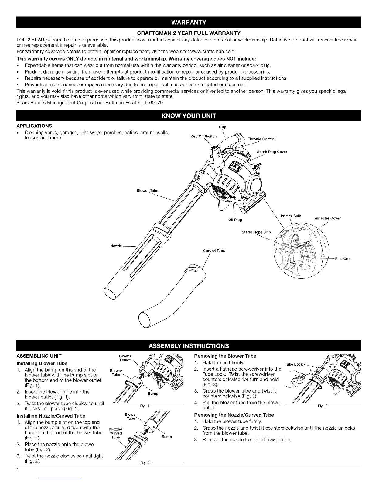
APPLICATIONS
• Cleaning yards, garages, driveways, porches, patios, around walls,
fences and more
Blower Tube
Nozzle --
On/Off Switch
Curved Tube
G ip
Oil Plug
Throttle Control
Spark Plug Cover
Starer Rope Grip
Primer Bulb
Air Filter Cover
ASSEMBLING UNIT
Installing Blower Tube
1. Align the bump on the end of the
blower tube with the bump slot on
the bottom end of the blower outlet
Blower
Tube
Blower
Outlet _
(Fig. 1).
2. Insert the blower tube into the
blower outlet (Fig. 1).
3. Twist the blower tube clockwise until
it locks into place (Fig. 1).
Installing Nozzle/Curved Tube
1.
Align the bump slot on the top end
of the nozzle/curved tube with the
bump on the end of the blower tube
B,.... ////
Nozzle/ _,_ "_
Curved f..=_"_
(Fig. 2).
2,
Place the nozzle onto the blower
tube (Fig. 2).
3.
Twist the nozzle clockwise until tight
Tu_ Bump
(Fig. 2).
Fig. 1
Fig. 2
Bump
Removing the Blower Tube
1. Hold the unit firmly.
2. Insert a flathead screwdriver into the
Tube Lock. Twist the screwdriver
counterclockwise 1/4 turn and hold
(Fig. 3).
3. Grasp the blower tube and twist it
counterclockwise (Fig. 3).
4. Pull the blower tube from the blower
outlet.
Fig. 3
Removing the Nozzle/Curved Tube
1. Hold the blower tube firmly.
2. Grasp the nozzle and twist it counterclockwise until the nozzle unlocks
from the blower tube.
3. Remove the nozzle from the blower tube.
RECOMMENDED OIL TYPE
FUELING THE UNIT
WARNING: OVERFILLING OIL CRANKCASE MAY CAUSE
SERIOUS PERSONAL INJURY. Check and maintain the
proper oil level in the crankcase; it is important and cannot be
overemphasized. Check the oil before each use and change it as
needed. See Changing the Oil.
Using the proper type and weight of oil in the crankcase is extremely
important. Check the oil before each use and change the oil regularly. Failure
to use the correct oil, or using dirty oil, can cause premature engine wear
and failure.
Use a high-quality SAE 30 weight oil
of API (American Petroleum Institute)
service class SF, SG, SH.
ADDING OIL TO CRANKCASE: INITIAL
USE
NOTE: This unit is shipped without
oil in the engine. To avoid
damage to the unit, put oil in
the crankcase prior to starting
the unit.
Fig. 4
This unit is supplied with one 2.03 fl.oz.
(60 ml) bottle of SAE 30 SF, SG, SH oil
(Fig. 7).
NOTE: Save the empty oil bottle. It
can be used to measure the
i
correct amount during future oil
changes. See Changing the Oil.
Oil Plu_
1. Unscrew the top of the bottle of oil
and remove the paper seal covering
the opening. Replace the top and cut
Fig. 5
the tip off the funnel spout (Fig. 4).
2. With the unit on a flat level surface,
remove the oil plug (Fig. 5).
3. Pour the entire bottle of oil into the
oil fill hole (Fig. 6).
NOTE: Never add oil to the fuel or fuel
tank.
:::: .......... Oil Fill Hole
4. Wipe up any oil that may have spilled
and reinstall the oil fill plug.
Check oil before each use and change
Fig. 6
as needed. Refer to Checking the Oil Level.
RECOMMENDED FUEL TYPE
Old fuel is the primary reason for poor unit performance. Be sure to use
fresh, clean, unleaded gasoline.
NOTE: This is a four cycle engine. In order to avoid damage to the unit, do
not mix oil with gasoline.
Definition of Blended Fuels
_, WARNING: Fuel containing greater than 15% ethanol will
likely damage the engine and void the warranty.
Today's fuels are often a blend of gasoline and oxygenates such as ethanol,
methanol or MTBE (ether). Alcohol-blended fuel absorbs water. As little as
1% water in the fuel can form acids when stored. Use fresh fuel (less than 30
days old), when using alcohol-blended fuel.
Using Blended Fuels
If choosing to use a blended fuel, or its use is unavoidable, follow
recommended precautions:
• Always use fresh unleaded gasoline
• Use a gas stabilizer fuel additive
• Drain tank and run the engine dry before storing unit
Using Fuel Additives
The use of a gas stabilizer will inhibit corrosion and minimize the formation of
gum deposits for up to six (6) months. Add 0.8 oz. (23 ml.) of fuel additive per
gallon of fuel according to the instructions on the container. NEVER add fuel
additives directly to the unit's gas tank.
WARNING: Gasoline is extremely flammable. Ignited vapors
may explode. Always stop the engine and allow it to cool before
filling the fuel tank. Do not smoke while filling the tank. Keep
sparks and open flames at a distance from the area.
WARNING: Add fuel in a clean, level and well ventilated
outdoor area. Wipe up any spilled fuel immediately. Avoid creating
a source of ignition for spilled fuel. Do not start the engine until
fuel vapors dissipate.
1. Remove the fuel cap (Fig. 7).
WARNING: Remove fuel cap slowly to avoid injury from fuel
spray. Never operate the unit without the fuel cap securely in place.
2. Place the gas container's spout into
the fill hole on the fuel tank and fill.
NOTE: Do not overfill the tank.
3. Wipe up any gasoline that may have
spilled.
4. Reinstall the fuel cap.
5. Move the unit at least 30 ft. (9.1 m)
from the fueling source and site
before starting the engine.
NOTE: Dispose of any old gasoline in
Fuel Tank
Fig. 7
accordance to Federal, State and Local regulations.
WARNING: Operate this unit only in a well-ventilated outdoor
area. Carbon monoxide exhaust fumes can be lethal in a
confined area.
WARNING: Avoid accidental starting. Make sure to be in the
starting position when pulling the starter rope (Fig. 10). To avoid
serious injury, the operator and unit must be in a stable position
while starting.
NOTE: This unit has the Incredi-Pull TM starting system, which significantly
STARTING INSTRUCTIONS
NOTE: When starting the unit, make
1. Check the oil level in the crankcase.
2. Fill the fuel tank with fresh, clean
3. Slowly press the primer bulb 10
4. Place the choke lever in Position 1
NOTE: DO NOT squeeze the trigger
5. Crouch in the starting position and
6. Place the choke lever in Position 2
7. Pull the starter rope 3 to 5 times to
8. Squeeze the throttle control and
9. While squeezing the throttle control,
IF.,, the engine does not start, go back to step 3.
IF.,, the engine fails to start after a few attempts, place the choke lever
IF WARM... place the choke lever in Position 2, making sure to
STOPPING INSTRUCTIONS
1. Release the throttle control and allow the engine to cool down by idling.
2. Press and hold the On/Off Control switch in the OFF (O) position until the
reduces the effort required to pull the starter rope.
On/Off Control
sure it is not directed at
bystanders or loose debris.
Refer to Checking the Oil Level.
unleaded gasoline. Refer to Fueling
the Unit.
Fig. 8
times. Some amount of fuel should
be visible in the primer bulb and fuel
lines (Fig. 9).
(Fig. 9).
while starting (Fig. 8).
pull the starter rope 5 times (Fig. 10).
Primer Bulb
Fig. 9
(Fig. 9).
start the engine.
allow the engine to warm up for 30-
60 seconds.
place the choke lever in Position 3
(Fig. 9) and continue to warm for an
additional 60 sec. The unit may be
Fig. 10
used during this time.
in Position 3 and pull the starter rope 3 to 8 times. The engine
should start. If not, repeat.
NOT squeeze the throttle trigger, and follow steps 7 thru 9 above.
engine comes to a complete stop (Fig. 8).
Sta i1iingn
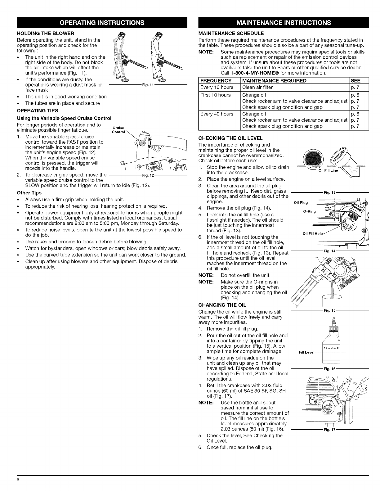
HOLDING THE BLOWER
Before operating the unit, stand in the
operating position and check for the
following:
• The unit in the right hand and on the
right side of the body. Do not block
the air intake which will affect the
unit's performance (Fig. 11).
• If the conditions are dusty, the
operator is wearing a dust mask or
face mask
• The unit is in good working condition
• The tubes are in place and secure
OPERATING TIPS
Using the Variable Speed Cruise Control
For longer periods of operation and to cruise
eliminate possible finger fatique.
1. Move the variable speed cruise
control toward the FAST position to
incrementally increase or maintain
the unit's engine speed (Fig. 12).
When the variable speed cruise
control is pressed, the trigger will
recede into the handle.
2. To decrease engine speed, move the Fig.12
variable speed cruise control to the
SLOW position and the trigger will return to idle (Fig. 12).
Other Tips
• Always use a firm grip when holding the unit.
• To reduce the risk of hearing loss, hearing protection is required.
• Operate power equipment only at reasonable hours when people might
not be disturbed. Comply with times listed in local ordinances. Usual
recommendations are 9:00 am to 5:00 pm, Monday through Saturday.
• To reduce noise levels, operate the unit at the lowest possible speed to
do the job.
• Use rakes and brooms to loosen debris before blowing.
• Watch for bystanders, open windows or cars; blow debris safely away.
• Use the curved tube extension so the unit can work closer to the ground.
• Clean up after using blowers and other equipment. Dispose of debris
appropriately.
' i
Fig. 11
MAINTENANCE SCHEDULE
Perform these required maintenance procedures at the frequency stated in
the table. These procedures should also be a part of any seasonal tune-up.
NOTE: Some maintenance procedures may require special tools or skills
FREQUENCY MAINTENANCE REQUIRED SEE
Every 10 hours Clean air filter p. 7
First 10 hours Change oil p. 6
Every 40 hours Change oil p. 6
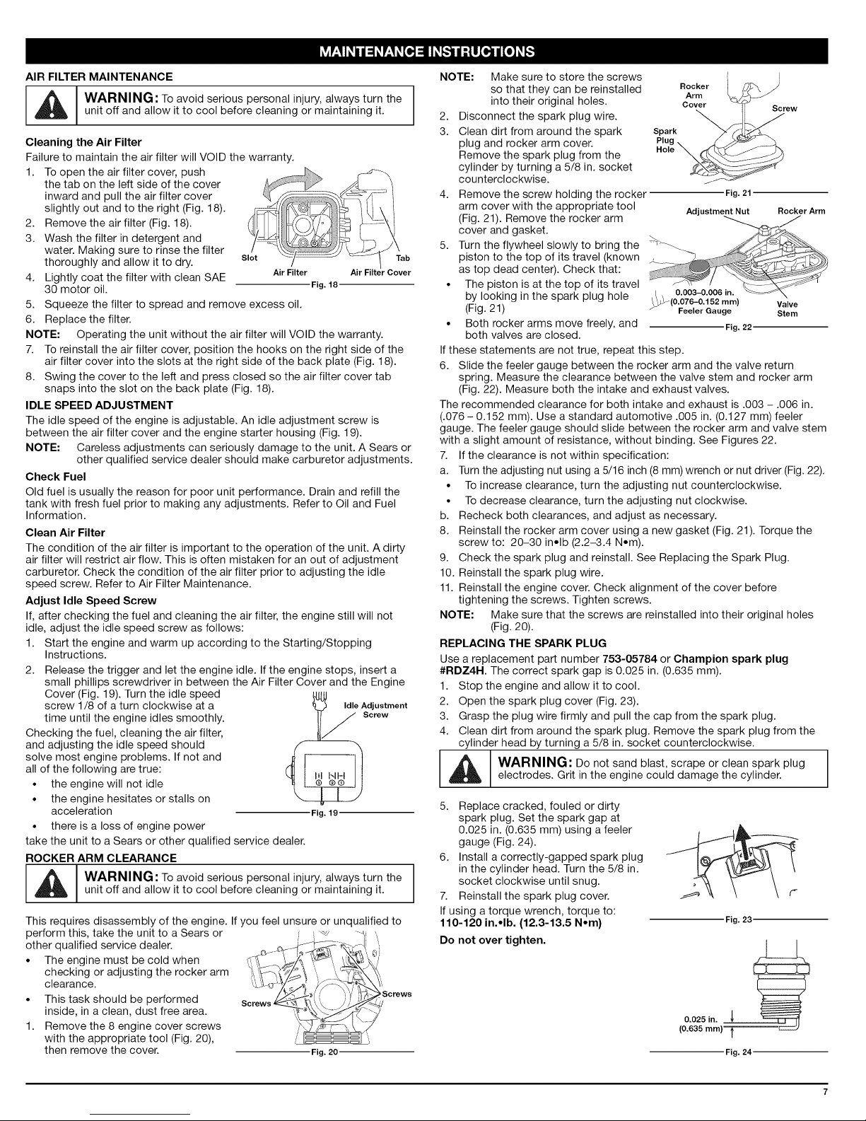
CHECKING THE OIL LEVEL
The importance of checking and
maintaining the proper oil level inthe
crankcase cannot be overemphasized.
Check oil before each use:
1. Stop the engine and allow oil to drain ............................_ ()ilFill Line- _ ....
2. Place the engine on a level surface.
3. Clean the area around the oil plug
4. Remove the oil plug (Fig. 14).
5. Look into the oil fill hole (use a
6. If the oil level is not touching the
NOTE: Do not overfill the unit.
NOTE: Make sure the O-ring is in
CHANGING THE OIL
Change the oil while the engine is still
warm. The oil will flow freely and carry
away more impurities.
1. Remove the oil fill plug.
2. Pour the oil out of the oil fill hole and
3. Wipe up any oil residue on the
4. Refill the crankcase with 2.03 fluid
NOTE: Use the bottle and spout
5. Check the level, See Checking the
6. Once full, replace the oil plug.
such as replacement or repair of the emission control devices
and system. If unsure about these procedures or tools are not
available; take the unit to Sears or other qualified service dealer.
Call 1-800-4-MY-HOME® for more information.
Check rocker arm to valve clearance and adjust p. 7
Check spark plug condition and gap p. 7
Check rocker arm to valve clearance and adjust p. 7
Check spark plug condition and gap p. 7
into the crankcase.
before removing it. Keep dirt, grass Fig.13.
clippings, and other debris out of the
engine. Oil Plug
O-Ring --
flashlight if needed). The oil should
be just touching the innermost
thread (Fig. 13). OilFillHole
innermost thread on the oil fill hole,
add a small amount of oil to the oil
fill hole and recheck (Fig. 13). Repeat
this procedure until the oil level
reaches the innermost thread on the
oil fill hole.
place on the oil plug when
checking and changing the oil
(Fig. 14).
into a container by tipping the unit
to a vertical position (Fig. 15). Allow
ample time for complete drainage. FillLevel
unit and clean up any oil that may
have spilled. Dispose of the oil
according to Federal, State and local
regulations.
ounce (60 ml) of SAE 30 SF, SG, SH
oil (Fig. 17).
saved from initial use to
measure the correct amount of
oil. The fill line on the bottle's
label measures approximately
2.03 ounces (60 ml) (Fig. 16).
Oil Level.
Fig. 14
Fig. 15
Fig. 16
Fig. 17
AIR FILTER MAINTENANCE
WARNING: To avoid serious personal injury, always turn the
unit off and allow it to cool before cleaning or maintaining it.
Cleaning the Air Filter
Failure to maintain the air filter will VOID the warranty.
1. To open the air filter cover, push
the tab on the left side of the cover
inward and pull the air filter cover
slightly out and to the right (Fig. 18).
2. Remove the air filter (Fig. 18).
3. Wash the filter in detergent and
water. Making sure to rinse the filter
thoroughly and allow it to dry. slot Tab
4. Lightly coat the filter with clean SAE Air Filter "Cover
30 motor oil. Fig.18
5. Squeeze the filter to spread and remove excess oil.
6. Replace the filter.
NOTE: Operating the unit without the air filter will VOID the warranty.
7. To reinstall the air filter cover, position the hooks on the right side of the
air filter cover into the slots at the right side of the back plate (Fig. 18).
8. Swing the cover to the left and press closed so the air filter cover tab
snaps into the slot on the back plate (Fig. 18).
IDLE SPEED ADJUSTMENT
The idle speed of the engine is adjustable. An idle adjustment screw is
between the air filter cover and the engine starter housing (Fig. 19).
NOTE: Careless adjustments can seriously damage to the unit. A Sears or
other qualified service dealer should make carburetor adjustments.
Check Fuel
Old fuel is usually the reason for poor unit performance. Drain and refill the
tank with fresh fuel prior to making any adjustments. Refer to Oil and Fuel
Information.
Clean Air Filter
The condition of the air filter is important to the operation of the unit. A dirty
air filter will restrict air flow. This is often mistaken for an out of adjustment
carburetor. Check the condition of the air filter prior to adjusting the idle
speed screw. Refer to Air Filter Maintenance.
Adjust Idle Speed Screw
If, after checking the fuel and cleaning the air filter, the engine still will not
idle, adjust the idle speed screw as follows:
1. Start the engine and warm up according to the Starting/Stopping
Instructions.
2. Release the trigger and let the engine idle. If the engine stops, insert a
small phillips screwdriver in between the Air Filter Cover and the Engine
Cover (Fig. 19). Turn the idle speed @U
screw 1/8 of a turn clockwise at a f_ IdleAdjustment
time until the engine idles smoothly. It J screw
Checking the fuel, cleaning the air filter,
and adjusting the idle speed should
solve most engine problems. If not and
all of the following are true:
• the engine will not idle
• the engine hesitates or stalls on
acceleration Fig. 19
• there is a loss of engine power
take the unit to a Sears or other qualified service dealer.
ROCKER ARM CLEARANCE
_IL WARNING: To avoid serious personal injury, always turn the
unit off and allow it to cool before cleaning or maintaining it.
This requires disassembly of the engine. If you feel unsure or unqualified to
perform this, take the unit to a Sears or -_-_
other qualified service dealer.
• The engine must be cold when
checking or adjusting the rocker arm
clearance.
• This task should be performed
inside, in a clean, dust free area.
1. Remove the 8 engine cover screws
with the appropriate tool (Fig. 20), \
then remove the cover. Fig.20
NOTE: Make sure to store the screws
so that they can be reinstalled
into their original holes.
2. Disconnect the spark plug wire.
Rocker
Arm
Cover
Screw
3. Clean dirt from around the spark Spark
plug and rocker arm cover, g
Remove the spark plug from the
cylinder by turning a 5/8 in. socket
counterclockwise.
4. Remove the screw holding the rocker
arm cover with the appropriate tool
(Fig. 21). Remove the rocker arm
Fig. 21
Adjustment Nut
Rocker Arm
cover and gasket.
5. Turn the flywheel slowly to bring the :>_
piston to the top of its travel (known
as top dead center). Check that:
• The piston is at the top of its travel
by looking in the spark plug hole
(Fig. 21)
• Both rocker arms move freely, and
both valves are closed.
_ 0.003-0.006 in.
9_(0.076-0.152 mm) Valve
Feeler Gauge Stem
Fig. 22
If these statements are not true, repeat this step.
6. Slide the feeler gauge between the rocker arm and the valve return
spring. Measure the clearance between the valve stem and rocker arm
(Fig. 22). Measure both the intake and exhaust valves.
The recommended clearance for both intake and exhaust is .003 - .006 in.
(.076 - 0.152 mm). Use a standard automotive .005 in. (0.127 mm) feeler
gauge. The feeler gauge should slide between the rocker arm and valve stem
with a slight amount of resistance, without binding. See Figures 22.
7. If the clearance is not within specification:
a. Turn the adjusting nut using a 5/16 inch (8 mm) wrench or nut driver (Fig. 22).
• To increase clearance, turn the adjusting nut counterclockwise.
• To decrease clearance, turn the adjusting nut clockwise.
b. Recheck both clearances, and adjust as necessary.
8. Reinstall the rocker arm cover using a new gasket (Fig. 21). Torque the
screw to: 20-30 in*lb (2.2-3.4 N.m).
9. Check the spark plug and reinstall. See Replacing the Spark Plug.
10. Reinstall the spark plug wire.
11. Reinstall the engine cover. Check alignment of the cover before
tightening the screws. Tighten screws.
NOTE: Make sure that the screws are reinstalled into their original holes
(Fig. 20).
REPLACING THE SPARK PLUG
Use a replacement part number 753-05784 or Champion spark plug
#RDZ4H. The correct spark gap is 0.025 in. (0.635 mm).
1. Stop the engine and allow it to cool.
2. Open the spark plug cover (Fig. 23).
3. Grasp the plug wire firmly and pull the cap from the spark plug.
4. Clean dirt from around the spark plug. Remove the spark plug from the
cylinder head by turning a 5/8 in. socket counterclockwise.
WARNING: Do not sand blast, scrape or clean spark plug
electrodes. Grit in the engine could damage the cylinder.
5. Replace cracked, fouled or dirty
spark plug. Set the spark gap at
0.025 in. (0.635 mm) using a feeler
gauge (Fig. 24).
6. Install a correctly-gapped spark plug
in the cylinder head. Turn the 5/8 in.
socket clockwise until snug.
7. Reinstall the spark plug cover.
If using a torque wrench, torque to:
110-120 in.*lb. (12.3-13.5 N.m)
Fig. 23
Do not over tighten.
(O.O325imnm)l_
Fig. 24

CLEANING
Use a small brush to clean off the outside of the unit. Do not use strong
detergents. Household cleaners that contain aromatic oils such as pine
and lemon, and solvents such as kerosene, can damage plastic housing or
handle. Wipe off any moisture with a soft cloth.
STORAGE
• Never store the unit with fuel in the tank where fumes may reach an open
flame or spark.
• Allow the engine to cool before storing.
• Lock up the unit to prevent unauthorized use or damage.
• Store the unit in a dry, well-ventilated are a.
• Store the unit out of the reach of children.
LONG TERM STORAGE
1. Drain all gasoline from the gas tank into a container. Do not use gas that
has been stored for more than 30 days. Dispose of the old gasoline in
accordance to Federal, State, and Local regulations.
2. Start the engine and allow it to run until it stalls. This ensures that all
gasoline has been drained from the carburetor.
PROBLEM SOLUTION
Primer bulb wasn't pressed enough Slowly press primer bulb 10 times
3. Allow the engine to cool. Remove the spark plug and put 5 drops of high
quality motor oil into the cylinder. Pull the starter rope slowly to distribute
the oil. Reinstall the spark plug.
NOTE: Remove the spark plug and drain all of the oil from the cylinder
before attempting to start the blower after storage.
4. Change the oil, referring to Changing the Oil. Dispose of the old oil in
accordance to Federal, State and Local regulations.
5. Thoroughly clean the unit and inspect for any loose or damaged parts.
Repair or replace damaged parts and tighten loose screws, nuts or bolts.
The unit is ready for storage.
TRANSPORTING
• Allow the engine to cool before transporting.
• Secure the unit while transporting.
• Drain the gas tank before transporting.
• Tighten gas cap before transporting.
Fouled spark plug Replace or clean the spark plug
Improper idle speed Adjust according to the Idle Speed Adjustments section.
Fouled spark plug Replace or clean the spark plug
NEED HORE HELP?
Y .... C ÷
YouI[fredtheanowerandmoreon ma agemyhfe°<om- forh'ee°
oFindthisandaH yourotherproductmanua[sonEne.
oGetanswersfromourteamofhome experts.
oGeta personaEzedmaintenancep[anforyourhome.
oFindinformationandtoo[stohelpwithhome projects.
@ aagernyl fe
 Loading...