

Page 1
Sears, Roebuck and Co., Hoffman Estates, IL 60179, U.S.A.
Visit our website: www.craftsman.com
CAUTION: Before using this
product, read this manual and
follow all safety rules and
operating instructions.
Operator’s Manual
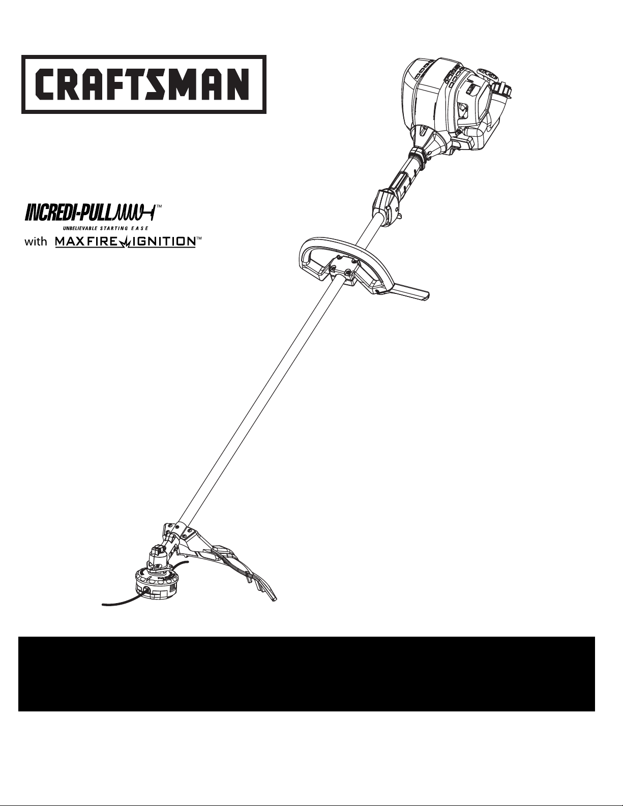
4-Cycle
GAS TRIMMER
Model No. 316.792021
• SAFETY
• ASSEMBLY
• OPERATION
• MAINTENANCE
• PARTS LIST
• ESPAÑOL, P. 15
FOR ANSWERS TO QUESTIONS ABOUT THIS PRODUCT, CALL 1-800-4-MY-HOME®
P/N 769-05876 P02 4/10
Plug-In Power Start or Power Bit Start Optional!
This unit has a separately sold alternative starting method that many find easier than pulling a
rope. For more information, contact a local Craftsman outlet or go to www.craftsman.com
®
Page 2
2
• IMPORTANT SAFETY INSTRUCTIONS •
READ ALL INSTRUCTIONS BEFORE OPERATING
• Read the instructions carefully. Be familiar with the controls and proper
use of the unit.
• Do not operate this unit when tired, ill, or under the influence of alcohol,
drugs, or medication.
• Children and teens under the age of 15 must not use the unit, except for
teens guided by an adult.
• All guards and safety attachments must be installed properly before
operating the unit.
• Inspect the unit before use. Replace damaged parts. Check for fuel leaks.
Make sure all fasteners are in place and secure. Replace parts that are
cracked, chipped, or damaged in any way. Do not operate the unit with loose
or damaged parts.
• Carefully inspect the area before starting the unit. Remove all debris and
hard or sharp objects such as glass, wire, etc.
•
Clear the area of children, bystanders, and pets. At a minimum, keep all
children, bystanders, and pets outside a 50 feet (15 m.) radius; there still may be
a risk to bystanders from thrown objects. Bystanders should be encouraged to
wear eye protection. If approached, stop the unit immediately.
• Use only Craftsman Hassle-Free™ XTRA QUIET Spiral Lineoriginal
equipment manufacturer replacement line. Never use metal-reinforced line,
wire or rope. These can break off and become dangerous projectiles.
• Squeeze the throttle control and check that it returns automatically to the idle
position. Make all adjustments or repairs before using unit.
SAFETY WARNINGS FOR GAS UNITS
• Store fuel only in containers specifically designed and approved for the
storage of such materials.
• Avoid creating a source of ignition for spilled fuel. Do not start the engine
until fuel vapors dissipate.
• Always stop the engine and allow it to cool before filling the fuel tank. Never
remove the cap of the fuel tank, or add fuel, when the engine is hot. Never
operate the unit without the fuel cap securely in place. Loosen the fuel tank
cap slowly to relieve any pressure in the tank.
•
Add fuel in a clean, well-ventilated outdoor area where there are no sparks or
flames. Slowly remove the fuel cap only after stopping engine. Do not smoke
while fueling. Wipe up any spilled fuel from the unit immediately. Always wipe unit
dry before using.
•
Move the unit at least 30 feet (9.1 m) from the fueling source and site before
starting the engine. Do not smoke or allow sparks and open flames near the area
while adding fuel or operating the unit.
WHILE OPERATING
• Never start or run the unit inside a closed room or building. Breathing exhaust
fumes can kill. Operate this unit only in a well ventilated outdoor area.
• Be aware of the risk of injury to the head, hands and feet.
•
Wear safety glasses or goggles that are marked as meeting ANSI Z87.1-1989
standards. Also wear ear/hearing protection when operating this unit. Wear a
face or dust mask if the operation is dusty. Long sleeve shirts are
recommended.
• Wear heavy, long pants, boots and gloves. Do not wear loose clothing,
jewelry, short pants, sandals or go barefoot. Secure hair above shoulder
level.
• The cutting attachment shield must always be in place while operating
the unit. Do not operate unit without both trimming lines extended, and
the proper line installed. Do not extend the trimming line beyond the
length of the shield.
• This unit has a clutch. The cutting attachment remains stationary when
the engine is idling. If it does not, have the unit adjusted by an authorized
service technician.
• Adjust the D-handle that will provide the best grip.
• Be sure the cutting attachment is not in contact with anything before
starting the unit.
• Use the unit only in daylight or good artificial light.
All information, illustrations, and specifications in this manual are based
on the latest product information available at the time of printing. We
reserve the right to make changes at any time without notice.
TABLE OF CONTENTS
Safety Rules . . . . . . . . . . . . . . . . . . . . . . . . . . . . . . . . . . . . . . . . . . . . . . . . .2
Warranty . . . . . . . . . . . . . . . . . . . . . . . . . . . . . . . . . . . . . . . . . . . . . . . . . . . .4
Know Your Unit . . . . . . . . . . . . . . . . . . . . . . . . . . . . . . . . . . . . . . . . . . . . . . .4
Assembly Instructions . . . . . . . . . . . . . . . . . . . . . . . . . . . . . . . . . . . . . . . . . .4
Oil and Fuel Information . . . . . . . . . . . . . . . . . . . . . . . . . . . . . . . . . . . . . . . .5
Starting/Stopping Instructions . . . . . . . . . . . . . . . . . . . . . . . . . . . . . . . . . . .6
Operating Instructions . . . . . . . . . . . . . . . . . . . . . . . . . . . . . . . . . . . . . . . . .7
Maintenance and Repair Instructions . . . . . . . . . . . . . . . . . . . . . . . . . . . . . .7
Cleaning and Storage . . . . . . . . . . . . . . . . . . . . . . . . . . . . . . . . . . . . . . . . .11
Optional Equipment . . . . . . . . . . . . . . . . . . . . . . . . . . . . . . . . . . . . . . . . . .11
Troubleshooting Chart . . . . . . . . . . . . . . . . . . . . . . . . . . . . . . . . . . . . . . . .12
Specifications . . . . . . . . . . . . . . . . . . . . . . . . . . . . . . . . . . . . . . . . . . . . . . .13
Parts List . . . . . . . . . . . . . . . . . . . . . . . . . . . . . . . . . . . . . . . . . . . . . . . . . . .30
Service Numbers . . . . . . . . . . . . . . . . . . . . . . . . . . . . . . . . . . . . .Back Cover
RULES FOR SAFE OPERATION
SPARK ARRESTOR NOTE
NOTE: For users on U.S. Forest Land and in the states of California, Maine,
Oregon and Washington. All U.S. Forest Land and the state of California (Public
Resources Codes 4442 and 4443), Oregon and Washington require, by law that
certain internal combustion engines operated on forest brush and/or grass-covered
areas be equipped with a spark arrestor, maintained in effective working order, or
the engine be constructed, equipped and maintained for the prevention of fire.
Check with your state or local authorities for regulations pertaining to these
requirements. Failure to follow these requirements could subject you to liability or
a fine. This unit is factory equipped with a spark arrestor. If it requires
replacement, ask your LOCAL SERVICE DEALER to install the Accessory Part
#
753-06334
Muffler Assembly.
CALIFORNIA PROPOSITION 65 WARNING
WARNING
THE ENGINE EXHAUST FROM THIS PRODUCT CONTAINS CHEMICALS
KNOWN TO THE STATE OF CALIFORNIA TO CAUSE CANCER, BIRTH
DEFECTS OR OTHER REPRODUCTIVE HARM.
NOTE- This Unit Can Use a Plug-In Power Start or Power Bit Start
Optional Accessory!
Please refer to the Plug-In Power Start or Power Bit Start operator’s
manual for proper use of these features. (Items may be Sold
Separately! Please refer to page 11 of this manual for more information
about purchasing these accessories.)
Read the Operator’s Manual and follow all warnings and safety instructions.
Failure to do so can result in serious injury to the operator and/or bystanders.
FOR QUESTIONS, CALL 1-800-4-MY-HOME®
SYMBOL MEANING
WARNING:
Failure to obey a safety warning can result in injury to
yourself and others. Always follow the safety precautions to reduce the risk
of fire, electric shock and personal injury.
CAUTION:
Failure to obey a safety warning may result in
property damage or personal injury to yourself or to others. Always
follow the safety precautions to reduce the risk of fire, electric shock
and personal injury.
The purpose of safety symbols is to attract attention to possible dangers. The
safety symbols, and their explanations, deserve careful attention and
understanding. The safety warnings do not by themselves eliminate any danger.
The instructions or warnings they give are not substitutes for proper accident
prevention measures.
SAFETY ALERT:
Indicates danger, warning or caution.
Attention is required in order to avoid serious personal injury. May
be used in conjunction with other symbols or pictographs.
NOTE: Advises of information or instructions vital to the operation or
maintenance of the equipment.
DANGER:
Failure to obey a safety warning will result in serious
injury to yourself or to others. Always follow the safety precautions
to reduce the risk of fire, electric shock and personal injury.
WARNING:
Gasoline is highly flammable and its vapors can
explode if ignited. Take the following precautions:
Page 3
3
RULES FOR SAFE OPERATION
• Avoid accidental starting. Be in the starting position whenever pulling the
starter rope. The operator and unit must be in a stable position while
starting. See Starting/Stopping Instructions.
• Use the right tool. Only use this tool for the purpose intended.
• Do not overreach. Always keep proper footing and balance.
• Always hold the unit with both hands when operating. Keep a firm grip on
both the front and rear handle or grips.
• Keep hands, face, and feet at a distance from all moving parts. Do not touch
or try to stop the cutting attachment when it is rotating.
•
Do not touch the engine or muffler. These parts get extremely hot from
operation. They remain hot for a short time after turning off the unit.
•
Do not operate the engine faster than the speed needed to cut, trim or edge. Do
not run the engine at high speed when the unit is not in use.
• Always stop the engine when cutting is delayed or when walking from one
cutting location to another.
•
If striking or unit becomes entangled with a foreign object, stop the engine
immediately and check for damage. Do not operate before repairing damage. Do
not operate the unit with loose or damaged parts.
• Stop and switch the engine to off for maintenance, repair, or for changing
the cutting attachment or other attachments.
• Use only original equipment manufacturer replacement parts and
accessories for this unit, as listed in the Parts pages of this operator’s
manual. These are available from a Sears or other authorized service
dealer. Use of any unauthorized parts or accessories could lead to serious
injury to the user, or damage to the unit, and void the warranty.
• Keep unit clean of vegetation and other materials. They may become
lodged between the cutting attachment and shield.
• To reduce fire hazard, replace faulty muffler and spark arrestor. Keep the
engine and muffler free from grass, leaves or other debris.
OTHER SAFETY WARNINGS
• Never store the unit, with fuel in the tank, inside a building where fumes
may reach an open flame or spark.
• Allow the engine to cool before storing or transporting. Be sure to secure
the unit while transporting.
• Store the unit in a dry area, locked up or up high to prevent unauthorized
use or damage. Keep out of the reach of children.
• Never douse or squirt the unit with water or any other liquid. Keep handles
dry, clean and free from debris. Clean after each use. See the Cleaning
and Storage instructions.
•
Keep these instructions. Refer to them often and use them to instruct other users. If
loaning someone this unit, also loan them these instructions.
SAVE THESE INSTRUCTIONS
This operator's manual describes safety and international symbols and pictographs that may appear on this product. Read the operator's manual for complete
safety, assembly, operating and maintenance and repair information.
• SAFETY & INTERNATIONAL SYMBOLS •
SYMBOL MEANING
SYMBOL MEANING
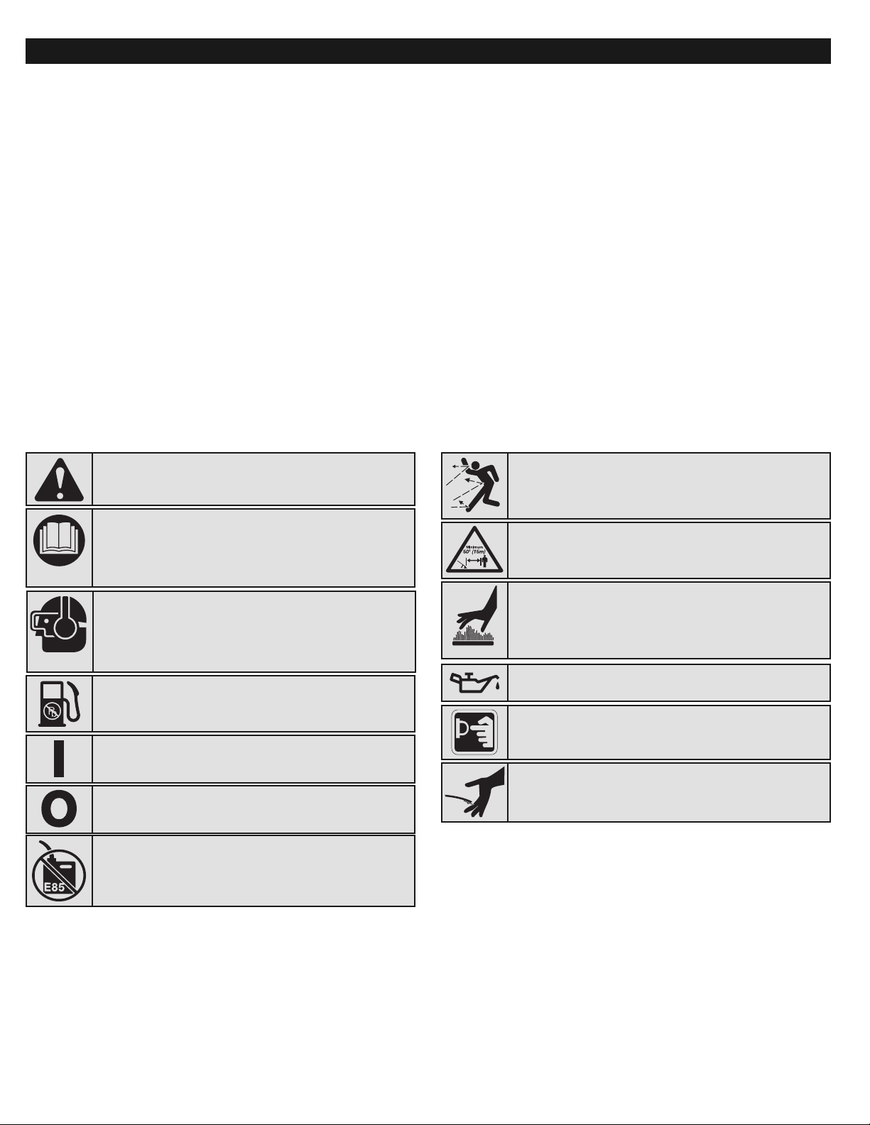
• SAFETY ALERT SYMBOL
Indicates danger, warning or caution. May be used in
conjunction with other symbols or pictographs.
• READ OPERATOR'S MANUAL
WARNING: Read the operator’s manual(s) and follow all
warnings and safety instructions. Failure to do so can result
in serious injury to the operator and/or bystanders.
• WEAR EYE AND HEARING PROTECTION
WARNING:
Thrown objects and loud noise can cause severe
eye injury and hearing loss. Wear eye protection meeting ANSI Z87.11989 standards and ear protection when operating this unit. Use a full
face shield when needed.
• UNLEADED FUEL
Always use clean, fresh unleaded fuel
• ON/OFF STOP CONTROL
ON / START / RUN
• ON/OFF STOP CONTROL
OFF or STOP
• HOT SURFACE
WARNING: Do not touch a hot engine. These parts get
extremely hot from operation and may cause severe burns.
When turned off they remain hot for a short time.
• KEEP BYSTANDERS AWAY
WARNING: Keep all bystanders, especially children and
pets, at least 50 feet (15 m.) from the operating area.
• THROWN OBJECTS AND ROTATING CUTTER CAN
CAUSE SEVERE INJURY
WARNING: Small objects can be propelled at high speed,
causing injury. Keep away from the rotating rotor.
• PRIMER BULB
Push primer bulb, fully and slowly, 10 times.
• OIL
Refer to operator’s manual for the proper type of oil.
• SHARP BLADE
WARNING:
Sharp blade on trimmer attachment shield. To
prevent serious injury, do not touch the line cutting blade.
• DO NOT USE E85 FUEL IN THIS UNIT
WARNING: It has been proven that fuel containing
greater than 15% ethanol will likely damage this engine and
void the warranty.
Page 4
APPLICATIONS
As a trimmer:
• Cutting grass and light weeds.
• Edging
• Decorative trimming around trees, fences, etc.
4
CRAFTSMAN PROFESSIONAL FULL WARRANTY
If this Craftsman Professional product fails due to a defect in material or workmanship within three years from the date of purchase, return it to any Sears store,
Parts & Repair Service Center, or other Craftsman outlet in the United States for free repair (or replacement if repair proves impossible).
This warranty applies for only one year if this product is ever used for commercial or rental purposes.
This warranty covers ONLY defects in material and workmanship. Sears will NOT pay for:
• Expendable items that can wear out from normal use within the warranty period, such as cutting line, filters or spark plugs.
• Repairs necessary because of accident or failure to operate or maintain the product according to all supplied instructions.
• Preventive maintenance, or repairs necessary due to improper fuel mixture, contaminated or stale fuel.
This warranty gives you specific legal rights, and you may also have other rights which vary from state to state.
Sears, Roebuck and Co., Hoffman Estates, IL 60179
WARRANTY STATEMENT
KNOW YOUR UNIT
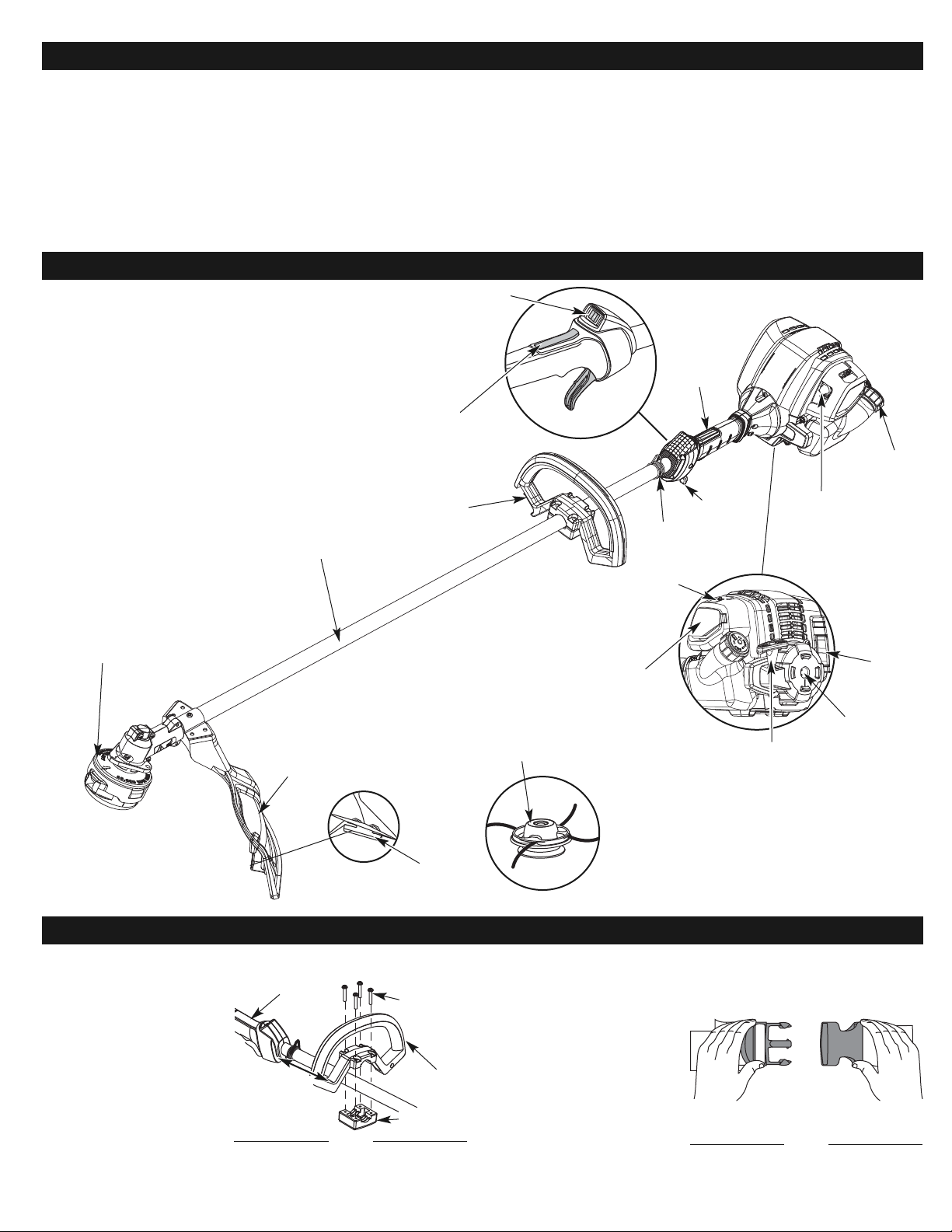
Cutting Head
Shield
Fuel Cap
D-Handle
Shaft Grip
Shaft Housing
Starter Rope
Grip
Throttle
Control
Air Filter
Cover
Electric Start
Adapter
Muffler
On/Off Control
Shoulder
Strap Loop
Primer Bulb
Line Cutting
Blade
INSTALL AND ADJUST THE D-HANDLE
1. Place D-handle over the
shaft housing and onto the
bottom clamp (Fig. 1). Place
it a minimum of 6 inches
(15.24 cm) from the end of
the shaft grip.
2. Start screws with a large
Flat-head or T-25 Torx
screwdriver. Do not tighten
until making the necessary
handle adjustment.
3. While holding the unit in the
operating position (Fig. 13),
move the D-handle to the
location that provides the best grip.
ASSEMBLY INSTRUCTIONS
4. Tighten the clamp screws evenly, until the D-handle is secure.
INSTALL THE SHOULDER SUPPORT
1. Put the shoulder support on
using the clip. (Fig. 2).
2. Adjust by lifting slightly on
the rear of the lower clip then
push or pull the loose end of
the strap length to fit the
operator’s size and comfort.
(Fig. 3).
3. Attach the shoulder clip to
the unit. (Fig. 4)
Screws (4)
Shaft Grip
Minimum 6 in.
(15.24 cm)
Fig. 1
Bottom
Clamp
D-Handle
Fig. 2
Throttle Lockout
Choke Lever
Rapid Rewind®Cutting
Head
Optional Hassle Free®PLUS
Cutting Head
Page 5
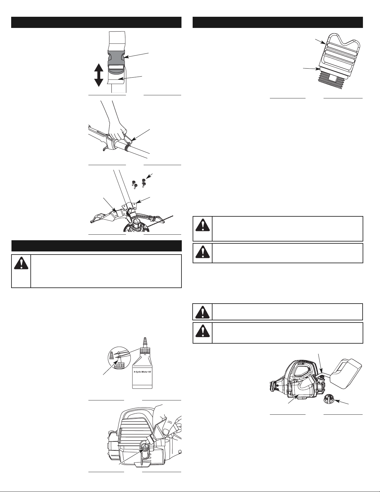
RECOMMENDED OIL TYPE
Using the proper type and weight of oil in the crankcase is extremely important.
Check the oil before each use and change the oil regularly. Failure to use the
correct oil, or using dirty oil, can cause premature engine wear and failure.
Use a high-quality SAE 30 weight oil of API (American Petroleum Institute) service
class SF, SG, SH.
ADDING OIL TO CRANKCASE: INITIAL USE
NOTE: This unit is shipped
without oil. In order to
avoid damage to the
unit, put oil in the
crankcase before
attempting to start the
unit.
The unit is supplied with one 2.2
fl.oz. (60 ml.) bottle of SAE 30 SF,
SG, SH oil (Fig. 6).
NOTE: Save the bottle of oil. It
can be used to measure
the correct amount
during future oil
changes. See Changing
the Oil.
1. Unscrew the top of the
bottle of oil and remove the
paper seal covering the
opening. Replace the top.
Next, cut the tip off the
funnel spout (Fig. 6).
2. Place unit on a flat, level
surface.
OIL & FUEL INFORMATION
WARNING:
OVERFILLING OIL CRANKCASE MAY CAUSE
SERIOUS PERSONAL INJURY. Check and maintain the proper oil
level in the crankcase; it is important and cannot be
overemphasized. Check the oil before each use and change it as
needed. See Changing the Oil.
3.
Remove the oil fill plug from the
crankcase (Fig. 8).
4. Pour the entire bottle of oil into
the oil fill hole (Fig. 7).
NOTE: Never add oil to the fuel
or fuel tank.
5. Wipe up any oil that may
have spilled and reinstall the
oil fill plug.
Check oil before each use and
change as needed. Refer to
Checking the Oil Level.
RECOMMENDED FUEL TYPE
Old fuel is the primary reason for improper unit performance. Be sure to use
fresh, clean, unleaded gasoline.
NOTE: Dispose of the old gasoline in accordance to Federal, State and
Local regulations.
NOTE: This is a four cycle engine. In order to avoid damage to the unit, do
not mix oil with gasoline.
Definition of Blended Fuels
Today's fuels are often a blend of gasoline and oxygenates such as ethanol,
methanol or MTBE (ether). Alcohol-blended fuel absorbs water. As little as 1%
water in the fuel can make fuel and oil separate or form acids when stored.
Use fresh fuel (less than 30 days old), when using alcohol-blended fuel.
Using Blended Fuels
If choosing to use a blended fuel, or its use is unavoidable, follow
recommended precautions:
• Always use fresh unleaded gasoline
• Use the fuel additive STA-BIL® or an equivalent
• Drain tank and run the engine dry before storing unit
Using Fuel Additives
The use of fuel additives, such as STA-BIL® Gas Stabilizer or an equivalent, will
inhibit corrosion and minimize the formation of gum deposits. Using a fuel additive
can keep fuel from forming harmful deposits in the carburetor for up to six (6)
months. Add 0.8 oz. (23 ml.) of fuel additive per gallon of fuel according to the
instructions on the fuel additive container. NEVER add fuel additives directly to the
unit's gas tank.
FUELING THE UNIT
1. Remove the fuel cap (Fig. 9).
2. Place the gas container’s
spout into the fill hole on the
fuel tank (Fig. 9) and fill the
tank.
NOTE: Do not overfill the tank.
3. Wipe up any gasoline that
may have spilled.
4. Reinstall the fuel cap.
5. Move the unit at least 30 ft.
(9.1 m) from the fueling
source and site before
starting the engine.
Funnel
Spout
Fig. 6
O-Ring
Oil Fill Plug
Fig. 8
Oil Fill Hole
Fig. 7
ASSEMBLY INSTRUCTIONS
INSTALL THE CUTTING HEAD
SHIELD
1. Place the cutting head shield
onto the guard mount
bracket, making sure to align
the holes on the shield with
the ones in the guard mount
bracket. (Fig. 5)
2. Take the 4 shield screws and
screw each one into the
shield until finger tight.
3. Using a Flat Head or T-20
screw driver, tighten the
screws until the shield is
firmly in place. (Fig. 5)
Fig. 3
Fig. 4
Fig. 5
OIL & FUEL INFORMATION
Support
Clip
Adjustment
Ta b
Support
Fitting
Guard Mount
Bracket
Cutting
Head
Shield
Screws (4)
WARNING:
Gasoline is extremely flammable. Ignited vapors
may explode. Always stop the engine and allow it to cool before
filling the fuel tank. Do not smoke while filling the tank. Keep
sparks and open flames at a distance from the area.
WARNING:
Add fuel in a clean, well ventilated outdoor area. Wipe
up any spilled fuel immediately. Avoid creating a source of ignition for
spilt fuel. Do not start the engine until fuel vapors dissipate.
Fuel
Cap
Fuel Tank
Fig. 9
WARNING:
Remove fuel cap slowly to avoid injury from fuel
spray. Never operate the unit without the fuel cap securely in place.
Gas Can Spout
WARNING:
DO NOT USE E85 FUEL IN THIS UNIT. It has been
proven that fuel containing greater than 15% ethanol will likely
damage this engine and void the warranty.
5
Page 6
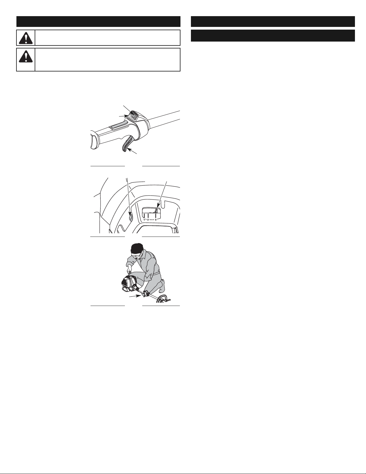
NOTE: This unit uses the Incredi-Pull™ starting system, which
significantly reduces the effort required to start the engine. There is
no harsh resistance when pulling the starter rope. Be aware that
this starting method is vastly different from (and much easier than)
previous starting techniques.
STARTING INSTRUCTIONS
1. Check the oil level in the
crankcase. Refer to
Checking the Oil Level.
2. Fill the fuel tank with fresh,
clean unleaded gasoline.
Refer to Fueling the Unit.
NOTE: There is no need to turn
the unit on. The On/Off
Control is in the ON ( I )
position at all times
(Fig. 10).
3. Fully press and release the
primer bulb 10 times, slowly.
Some amount of fuel should
be visible in the primer bulb
and fuel lines (Fig. 11). If fuel
cannot be seen in the primer
bulb, press and release the
bulb until fuel is visible.
4. Place the choke lever in
Position 1 (Fig. 11).
5. Crouch in the starting
position (Fig. 12). Press the
throttle lockout in and fully
squeeze the throttle control
lever. Pull the starter rope 5
times.
6. Place the choke lever in
Position 2 (Fig. 11).
7. While pressing the throttle
lockout in and squeezing the
throttle control , pull the
starter rope 3 to 5 times to
start the engine.
8. Keep the throttle squeezed
and allow the engine to warm
up for 30 to 60 seconds.
9. Continue squeezing the
throttle control, move the choke lever to Position 3 (Fig. 11) and
continue warming the engine for an additional 60 seconds. The unit
may be used during this time.
NOTE: Unit is properly warmed up when engine accelerates without
hesitation.
IF... the engine hesitates, return the choke lever to Position 2 (Fig. 11)
and continue warm-up.
IF... the engine does not start, go back to step 3.
IF... the engine fails to start after a few attempts, place the choke lever
in Position 3 and squeeze the throttle control. Pull the starter rope
out with a controlled and steady motion 3 to 8 times. The engine
should start. If not, repeat.
IF WARM... If the engine is already warm, start the unit with the choke lever
in Position 2. After the unit starts, move the choke lever to
Position 3.
STOPPING INSTRUCTIONS
1. Release the throttle control and allow the engine to cool down by idling.
2. Press and hold On/Off Control in the OFF (O) position until engine
comes to a complete stop (Fig. 10).
STARTING/STOPPING INSTRUCTIONS
WARNING:
Operate this unit only in a well-ventilated outdoor area.
Carbon monoxide exhaust fumes can be lethal in a confined area.
WARNING:
Avoid accidental starting. Make sure to be in the
starting position when pulling the starter rope (Fig. 12). To avoid
serious injury, the operator and unit must be in a stable position
while starting.
Start/On ( I )
Stop/Off (O)
Throttle Control
Fig. 10
Starting
Position
Throttle Control
Fig. 12
Choke Lever
Fig. 11
STARTING/STOPPING INSTRUCTIONS
Primer Bulb
6
NOTE- This Unit Can Use a Plug-In Power Start or Power Bit Start
Optional Accessory!
Please refer to the Plug-In Power Start or Power Bit Start operator’s
manual for proper use of these features. (Items may be Sold
Separately! Please refer to page 11 of this manual for more information
about purchasing these accessories.)
STARTING INSTRUCTIONS
1. Check the oil level in the crankcase. Refer to Checking the Oil Level.
2. Fill the fuel tank with fresh, clean unleaded gasoline. Refer to Fueling
the Unit.
NOTE: There is no need to turn the unit on. The On/Off Control is in the ON ( I )
position at all times (Fig. 10).
3. Fully press and release the primer bulb 10 times, slowly. Some amount
of fuel should be visible in the primer bulb and fuel lines (Fig. 11). If fuel
cannot be seen in the primer bulb, press and release the bulb until fuel
is visible.
4. Place the choke lever in Position 1 (Fig. 11).
5. Crouch in the starting position (Fig. 12).Place the electric starter or
power start bit into the back of the unit. Refer to the Operation section
of the Electric Starter or Power Start Bit™ operator’s manual.
6. Press the throttle lockout in and fully squeeze the throttle control lever.
Press and hold the electric starter or drill ON (I) button for 2 seconds.
7. Place the choke lever in Position 2 (Fig. 11).
8. While pressing the throttle lockout in and squeezing the throttle control,
press and hold the electric starter or drill ON (I) button for 2 second
intervals until unit starts.
9. Continue to squeeze the throttle control, remove the electric starter or
drill from the unit and allow the engine to warm up for 30 to 60
seconds.
10. Continue squeezing the throttle control, move the choke lever to
Position 3 (Fig. 11) and run the unit for an additional 60 seconds. The
unit may be used during this time.
NOTE: Unit is properly warmed up when engine accelerates without
hesitation.
IF... the engine hesitates, return the choke lever to Position 2 (Fig. 11)
and continue warm-up.
IF... the engine does not start, go back to step 3.
IF... the engine fails to start after a few attempts, place the choke lever
in Position 3 and squeeze the throttle control. Press and hold the
electric starter or drill ON (I) button for 2-second intervals until the
unit starts.
IF WARM... If the engine is already warm, start the unit with the choke lever
in Position 2. After the unit starts, move the choke lever to
Position 3.
STOPPING INSTRUCTIONS
1. Release the throttle control and allow the engine to cool down by idling.
2. Press and hold On/Off Control in the OFF (O) position until engine
comes to a complete stop (Fig. 10).
IF USING THE OPTIONAL POWER START OR POWER START BIT™
ACCESSORY
Page 7
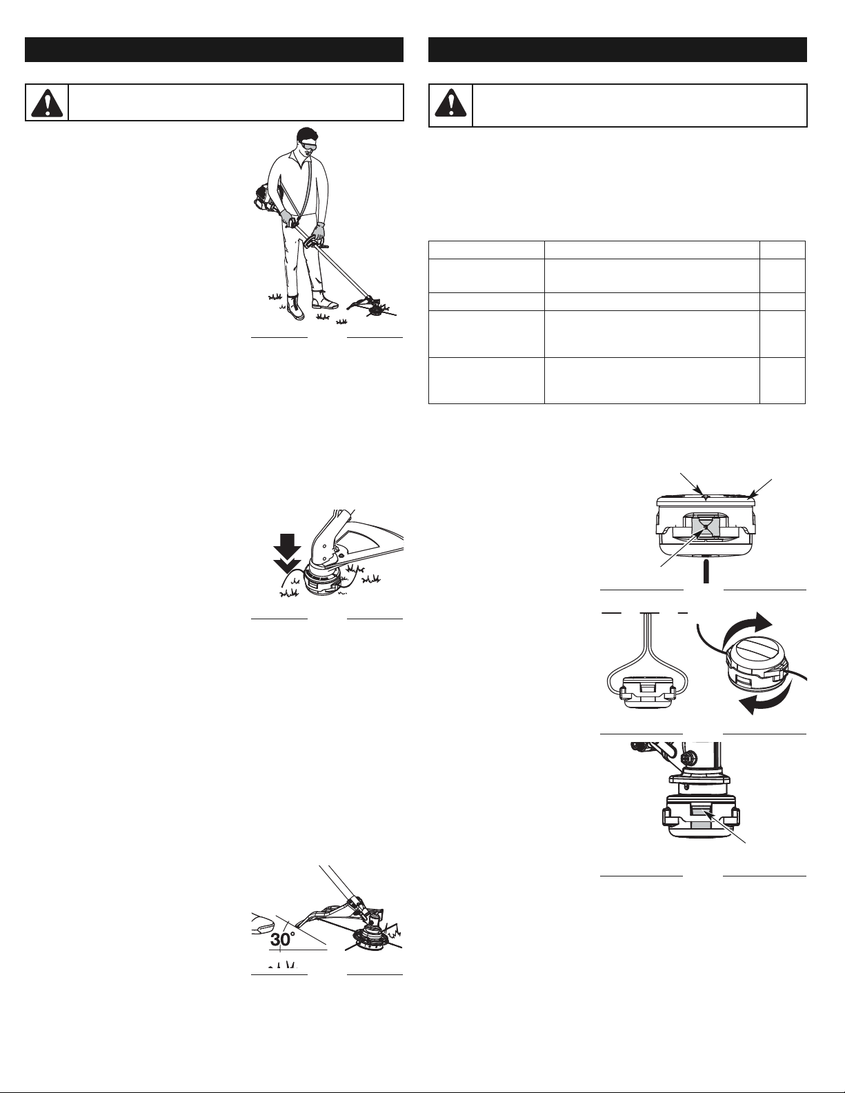
7
HOLDING THE TRIMMER
Before operating the unit, stand in the
operating position (Fig. 13). Check for the
following:
• The operator is wearing eye protection and
proper clothing
• With a slightly-bent right arm, the
operator’s right hand is holding the shaft
grip
• The operator’s left arm is straight, the left
hand holding the handle
• The unit is at waist level
• The cutting attachment is parallel to the
ground and easily contacts the grass
without the need to bend over
ADJUSTING TRIMMING LINE LENGTH
The cutting head allows the release of
trimming line without stopping the engine. To
release more line, lightly tap the cutting attachment on the ground (Fig. 14)
while operating the trimmer at high speed.
NOTE: Always keep the trimming line fully extended. Line release
becomes more difficult as the cutting line becomes shorter.
Each time the head is bumped, about 1 inch (25.4 mm) of trimming line is
released. A blade in the cutting attachment shield will cut the line to the
proper length if excess line is released.
For best results, tap the cutting head on bare ground or hard soil. If line
release is attempted in tall grass, the engine may stall. Always keep the
trimming line fully extended. Line release becomes more difficult as the
cutting line becomes shorter.
NOTE: Do not rest the cutting head on the ground while the unit is
running.
Some line breakage will occur from:
• Entanglement with foreign matter
• Normal line fatigue
• Attempting to cut thick, stalky weeds
• Forcing the line into objects such as walls
or fence posts
TIPS FOR BEST TRIMMING RESULTS
• Keep the cutting attachment parallel to the
ground.
• Do not force the cutting attachment. Allow the tip of the line to do the
cutting, especially along walls. Cutting with more than the tip will reduce
cutting efficiency and may overload the engine.
• Cut grass over 8 inches (200 mm) by working from top to bottom in small
increments to avoid premature line wear or engine drag.
• Slowly move the trimmer into and out of the cutting area at the desired
height. Move either in a forward-backward or side-to-side motion. Cutting
shorter lengths produces the best results.
• Trim only when grass and weeds are dry.
• The cutting head and shield are designed to allow the unit to cut in either
direction, from right to left or left to right.
• The life of the cutting line is dependent upon:
- Proper adherence of explained trimming techniques
- What vegetation is cut
- Where vegetation is cut
For example, the line will wear faster when trimming against a foundation
wall as opposed to trimming around a tree.
DECORATIVE TRIMMING
Decorative trimming is accomplished by
removing all vegetation around trees, posts,
fences and more.
Rotate the whole unit so that the cutting
attachment is at a 30° angle to the ground
(Fig. 15).
WARNING:
Always wear eye, hearing, foot and body protection
to reduce the risk of injury when operating this unit.
Fig. 13
Fig. 15
OPERATING INSTRUCTIONS
Fig. 14
RAPID REWIND™ CUTTING HEAD LINE INSTALLATION
Only use 0.095 in. (2.41 mm) replacement line. Other line width may make the
engine overheat or fail.
NOTE: There may be a need to
remove the old line prior
to installing new line. If
so, please refer to
Removing the old line or
obstructions.
1. Align the arrows on the cutting
head knob with the outer
spool eyelets, if they are not
already.(Fig. 16)
2.
Using 10.5 ft. (3.2 m) of 0.095
in. (2.41 mm) replacement line
push an end of the line through
one of the eyelets until it
protrudes through the opposite
side. Continue pushing or
pulling the line until the line is
evenly distributed, so
approximately 5 ft. (1.5 m) is
visible from both sides of the
cutting head.(Fig. 17)
3.
Hold the cutting head knob and
turn the cutting head clockwise
to wind the line around the
inner reel until 5 in. (12.7 cm) is
protruding from each side of
the cutting head.(Fig. 17)
NOTE: If winding the line from a
large spool, push
approximately 5 ft. (1.5 m)
of line through the cutting
head to the other side.
Turn the cutting head to
wind the line in. When the
line winds to a distance of
5 in. from the head, cut
the line on the spool side 5 inches from the head.
4. Start the unit and bump the cutting head on the ground until the desired
cutting length is achieved.
MAINTENANCE SCHEDULE
Perform these required maintenance procedures at the frequency stated in
the table. These procedures should also be a part of any seasonal tune-up.
NOTE: Some maintenance procedures may require special tools or skills. If
unsure about these procedures take the unit to Sears or other qualified
service dealer. Call 1-800-4-MY-HOME® for more information.
NOTE: Maintenance, replacement, or repair of the emission control devices
and system may be performed by a Sears or other qualified service
dealer. Call 1-800-4-MY-HOME® for more information.
WARNING:
To prevent serious injury, never perform
maintenance or repairs with unit running. Always service and
repair a cool unit.
FREQUENCY MAINTENANCE REQUIRED SEE
Before starting
engine
Fill fuel tank with fresh fuel
Check oil
p. 6
p. 9
Every 10 hours Clean air filter p. 9
1st change at 10
hours
Every 40 hours after
Change oil
Clean spark arrestor and change oil
p. 9
p. 11
Every 40 hours Check rocker arm to valve clearance
and adjust
Check spark plug condition and gap
p. 10
p. 11
Cutting
Head Knob
Eyelet
Fig. 16
Fig. 17
Arrow
Fig. 18
Ta b
MAINTENANCE & REPAIR INSTRUCTIONS
Page 8
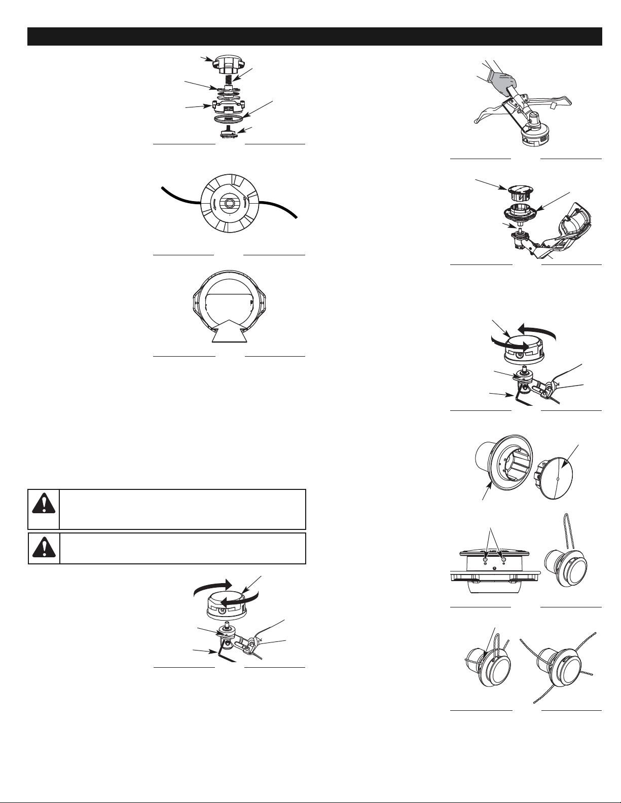
8
Removing the Hassle-Free™ PLUS Cutting Head
1. Align the output shaft bushing
hole with the locking rod slot
and insert the locking rod into
the output shaft bushing hole
(Fig. 22).
2. Hold the locking rod in place
by grasping it next to the
shaft housing of the unit (Fig.
23).
3. Use a 1/2 in (13 mm) wrench
to remove the cutting head
from the output shaft on the
gearbox by turning
clockwise. (Fig. 24)
Installing the Rapid Rewind™
cutting head
1. Align the output shaft bushing
hole with the locking rod slot
and insert the locking rod into
the shaft bushing hole (Fig.
25).
2. Hold the locking rod in place
by grasping it next to the
shaft housing of the unit (Fig. 23).
3. Screw the cutting head counterclockwise onto the output shaft. Tighten
securely. (Fig. 25) Remove the locking rod.
HASSLE-FREE™ PLUS LINE REPLACEMENT
Always use Craftsman HassleFree™ XTRA QUIET Spiral Line.
Choose the line size best suited
for the job at hand. Red colored
line is designed for cutting grass
and small weeds. Black colored
line is designed for cutting larger
weeds and light brush.
NOTE: Before inserting new line
into the holes in the
cutting head, identify the
proper holes. Follow
directions as shown on
the glide plate. Do Not
attempt to remove the
cutting head from the
unit when replacing line.
NOTE: Do not mix lines. Use 2
black or 2 red only.
1. Remove the old line and line
glide plate from the cutting
head.
2. Clean entire surface of
cutting head.
3. Reinstall line glide plate (Fig.
26). The glide plate is a keyed
item and will only fit one way.
If it does not go into the
cutting head smoothly, DO
NOT force it. Rotate the glide
plate until it slides into the
cutting head easily.
NOTE: The glide plate must be
installed in the cutting
head before inserting
new line.
4.
Insert both ends of the line
through the large holes in the
side of the cutting head (Fig. 27).
5.
Push and/or pull the line so that
the line is snug against the hub
and is fully extended through
the positioning tunnels. (Fig. 28)
6. Correctly installed line will be
the same length on both
sides.
NOTE: Make sure that when installing new line, that the line is as close to
even as possible. Any variation in lengths may cause the unit to
vibrate excessively. If this happens, stop the unit and make sure
the line is even.
7. Repeat steps 4 thru 6 to install the second trimmer line.
Glide Plate
Cutting Head
Large Holes
Fig. 27
REMOVING THE OLD LINE OR
OBSTRUCTIONS
NOTE: There should only be a
need to remove the
bump cap if there is an
obstruction or jammed
line preventing either
new line installation or
line advancement.
1. Firmly press in on the tabs that
are on each side of the cutting
head. (Fig. 18)
NOTE: It may be easier to press
in and then up on one
tab at a time.
2. Detach the bump cap either
by letting it pop off, or a
slight wiggle of the cap may
be required to pull it off the
outer spool (Fig. 19)
3. Remove any old line from the
inner reel or obstructions
from the outer spool. (Fig. 20)
4.
Place the inner reel back into the
outer spool (Fig. 19).
5. Reattach the bump cap by
aligning the tabs of the bump
cap with the tab lock
windows of the outer spool
and press down firmly until
both tabs snap back into
place. (Fig. 21)
To install new line, please refer to
the Rapid Rewind Cutting Head
Line Installation section.
CHANGING THE CUTTING HEADS
This unit was also shipped with a Hassle Free™ PLUS cutting head. Either cutting
head may be used at the operator’s discretion.
Removing the Rapid Rewind™ Cutting Head
1. Align the shaft bushing hole with the locking rod slot and insert the locking
rod into the output shaft bushing hole (Fig. 22).
2. Hold the locking rod in place by grasping it next to the shaft housing of
the unit (Fig. 23).
3. While holding the locking rod, remove the cutting head by turning it
clockwise off of the output shaft (Fig. 22). Store the cutting head for
future use.
Installing the Hassle Free™ PLUS Cutting Head
1. Place the cutting head onto
the output shaft and turn
counterclockwise until finger
tight. (Fig. 24)
2.
Align the output shaft bushing
hole with the locking rod slot
and insert the locking rod into
the shaft bushing hole (Fig. 22).
3. Hold the locking rod in place
by grasping it next to the
shaft housing of the unit (Fig.
23).
4. Using a 1/2 in (13 mm) open-end wrench, tighten the cutting head
securely in place. Remove the locking rod.
Refer to the Hassle-Free™ PLUS line replacement instructions, for line
installation.
WARNING:
The gear housing gets hot with use. It can result in
injury to the operator. The housing remains hot for a short time
even after the unit is turned off. Do not touch the gear housing
until it has cooled.
WARNING:
To avoid serious personal injury or damage to the
unit, do not start or operate this unit with the locking rod in the
locking rod slot.
Rapid Rewind™ Head
Output
Shaft
Bushing
Hole
Fig. 22
Fig. 23
Glide Plate
Fig. 24
Locking
Rod
Hassle Free™
PLUS Head
Output Shaft
Rapid Rewind™ Head
Output
Shaft
Bushing
Hole
Fig. 25
Locking
Rod
Fig. 21
PRESS
Fig. 19
Bump Cap
Inner
Reel
Outer
Spool
Spring
Gearbox
Fig. 20
Cutting
Head Knob
Positioning Tunnel
Fig. 28
MAINTENANCE & REPAIR INSTRUCTIONS
Page 9
9
MAINTENANCE & REPAIR INSTRUCTIONS
NOTE: Do not rest the Hassle-Free™ PLUS Cutting Head on the ground
while the unit is running.
Some line breakage will occur from:
• Entanglement with foreign matter
• Normal line fatigue
• Attempting to cut thick, stalky weeds
• Forcing the line into objects such as walls or fence posts
NOTE: During normal use the trimming line may become worn unevenly
which may cause excessive vibrations in the unit. If this becomes
uncomfortable or uncontrollable, stop the unit and replace the line.
Refer to the Line Replacement instructions above.
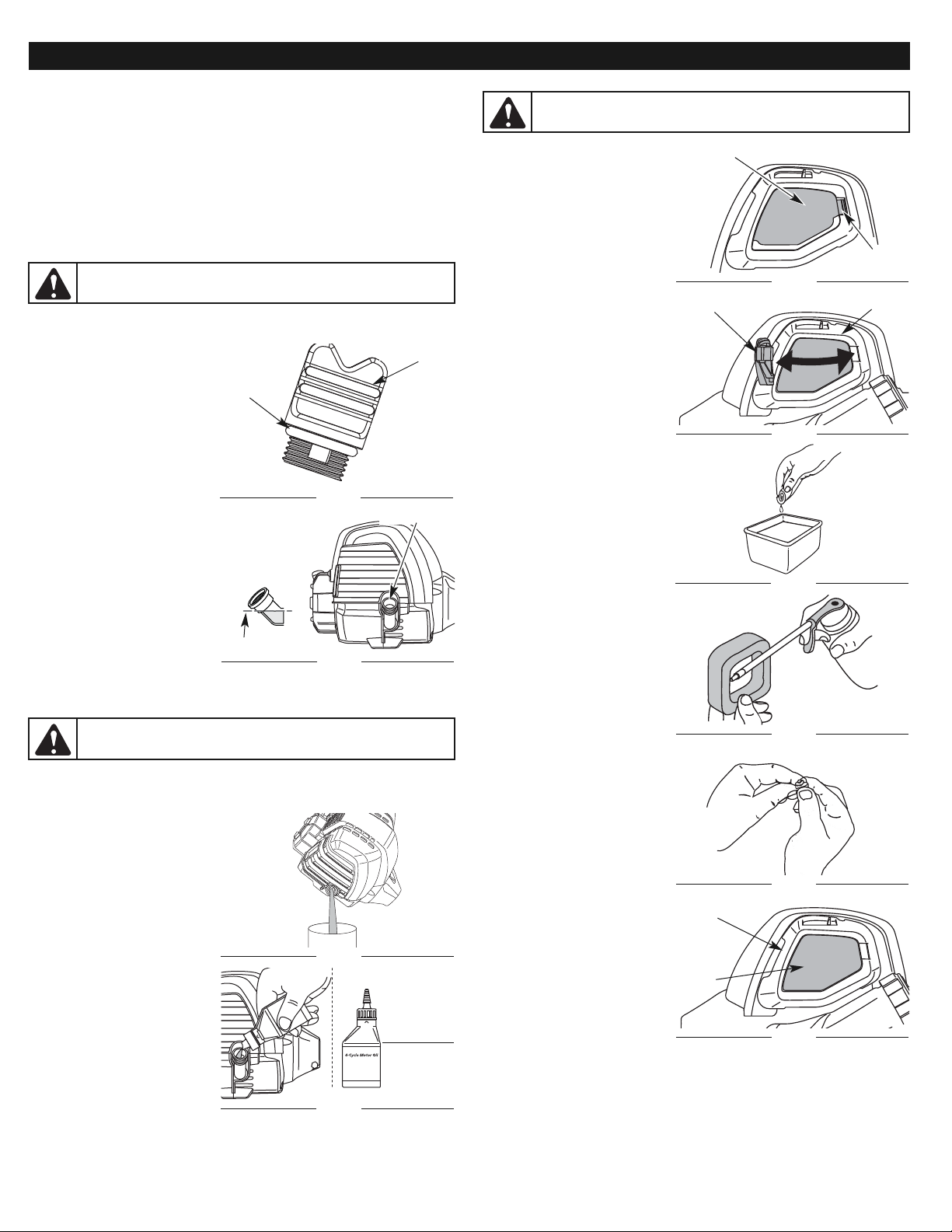
CHECKING THE OIL LEVEL
The importance of checking and maintaining the proper oil level in the
crankcase cannot be overemphasized. Check oil before each use:
1. Stop the engine and allow oil
to drain into the crankcase.
2. Place the unit on a flat, level
surface to get a proper oil
level reading.
3. Keep dirt, grass clippings
and other debris out of the
engine. Clean the area
around the oil fill plug before
removing it.
4. Remove the oil fill plug.
5. Check the oil level. Oil
should be just to the bottom
of the threads of the oil fill
hole. (Fig. 30).
6. If the level is low, add a small
amount of oil to the oil fill
hole and recheck (Fig. 30).
Repeat this procedure until
the oil level reaches the
bottom of the threads in the
oil fill hole.
NOTE: Do not overfill the unit.
NOTE: Make sure the O-ring is in place on the oil fill plug when checking and
changing the oil (Fig. 29).
CHANGING THE OIL
For a new engine, change the oil after the first 25 hours of operation. Change
the oil while the engine is still warm. The oil will flow freely and carry away
more impurities.
1. Remove the oil fill plug.
2. Pour the oil out of the oil fill hole
and into a container by tipping
the unit to the side (Fig. 31).
Allow ample time for complete
drainage.
3. Wipe up any oil residue on the
unit and clean up any oil that
may have spilled. Dispose of
the oil according to Federal,
State and local regulations.
4. Refill the crankcase with 2.2
fl. oz. (60 ml) of SAE 30 SF,
SG, SH oil.
NOTE: Use the bottle and
spout saved from initial
use to measure the
correct amount of oil.
The top of the label on
the bottle measures
approximately 3.04
ounces (90 ml) (Fig. 32).
Check the level (Fig. 25). If the level is low, add a small amount of
oil and recheck. Do not overfill.
5. Replace the oil fill plug.
WARNING:
To avoid serious personal injury, always turn the unit
off and allow it to cool before cleaning or servicing it.
O-Ring
Fig. 29
Oil Fill Plug
Oil Fill Hole
Fig. 30
Oil Full Line
Add 1.4-1.5 Oz.
(41-44 ml)
Fig. 32
CAUTION:
Wear gloves to prevent injury when handling the
unit.
Fill Line
Fig. 31
AIR FILTER MAINTENANCE
Cleaning the Air Filter
Clean the air filter every 10 hours
of operation. It is an important
item to maintain. Failure to
maintain the air filter properly can
result in poor performance or can
cause permanent damage to the
engine.
1. Open the air filter cover by
pressing the lock tab in and
pulling out on the air filter
cover (Fig. 33 & 34).
2.
Remove the air filter (Fig. 38).
3. Wash the filter in detergent
and water (Fig. 35). Rinse the
filter thoroughly and allow it to
dry.
4. Apply enough clean SAE 30
motor oil to lightly coat the
filter (Fig. 36).
5. Squeeze the filter to spread
and remove excess oil (Fig.
37).
6. Replace the air filter into the
base plate (Fig. 38).
NOTE: Operating the unit
without the air filter, will
VOID the warranty.
7. Reinstall the air filter cover.
Position the two small tabs
on the air filter cover into the
two slots in the back plate
and press the air filter cover
down, making sure to align
the lock tab with the lock tab
slot, until it snaps into place
(Fig. 34 & 33).
IDLE SPEED ADJUSTMENT
The idle speed of the engine is
adjustable. An idle adjustment
screw is between the air filter cover
and the engine starter housing
(Fig. 39).
NOTE: Careless adjustments
can seriously damage
the unit. Aside from idle
speed, only a Sears or
other authorized service
dealer should make
carburetor adjustments.
First, Check Fuel
Old fuel is usually the reason for
idle speed problems. Drain and
refill the tank with fresh fuel prior
to making any adjustments. Refer
to Oil and Fuel Information.
Second, Clean Air Filter
The condition of the air filter is
important to the operation of the
unit. A dirty air filter will restrict air
flow. This is often mistaken for an
out of adjustment idle. Check the
condition of the air filter before
adjusting the idle speed screw.
Refer to Air Filter Maintenance.
Fig. 35
Air Filter Cover
Lock Tab
Air Filter Cover
Back Plate
CAUTION:
Wear gloves to prevent injury when handling the
unit.
Fig. 34
Fig. 33
Fig. 38
Black
Plate
Air
Filter
Fig. 37
Fig. 36
Page 10
10
• Both rocker arms move
freely, and both valves are
closed
If these statements are not true,
repeat step 6.
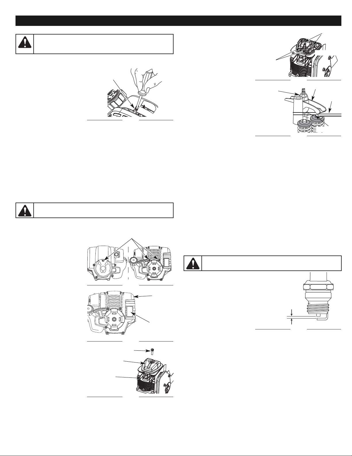
7. Slide the feeler gauge
between the rocker arm and
the top of each valve stem.
Measure the clearance
between the valve stem and
rocker arm (Fig. 43). Measure
both the intake and exhaust
valves.
The recommended clearance for both
intake and exhaust is .003 – .006 in.
(.076 – 0.152 mm). Use a standard
automotive .005 in. (0.127 mm) feeler
gauge. The feeler gauge should slide
between the rocker arm and valve
stem with a slight amount of
resistance, without binding. Figure 43
and 44 show how to measure the
clearance.
8. If the clearance is not within specification:
a.
Turn the adjusting nut using a 5/16 inch (8 mm) wrench or nut driver (Fig. 43).
• To increase clearance, turn the adjusting nut counterclockwise.
• To decrease clearance, turn the adjusting nut clockwise.
b. Recheck both clearances, and adjust as necessary.
9. Reinstall the rocker arm cover using a new gasket. Torque the screw to
20–30 in•lb (2.2–3.4 N•m).
10. Check the spark plug and reinstall. See Replacing the Spark Plug.
11. Replace the spark plug wire.
12. Reinstall the engine cover. Check alignment of the cover before
tightening the screws. Tighten screws.
REPLACING THE SPARK PLUG
Use a replacement Champion®RDZ4H spark plug. The correct air gap is
0.025 in. (0.635 mm). Remove the plug after every 25 hours of operation and
check its condition.
1. Stop the engine and allow it to cool. Remove the two (2) screws on
back of the engine cover and the one on the front of the engine cover
with a Flat-head or T-25 Torx screwdriver (Fig. 40).
2. Grasp the plug wire firmly and pull the cap from the spark plug.
3. Clean dirt from around the
spark plug. Remove the
spark plug from the cylinder
head by turning a 5/8 in.
socket counterclockwise.
4. Replace cracked, fouled or
dirty spark plug. Set the air
gap at 0.025 in. (0.635 mm)
using a feeler gauge (Fig. 45).
5. Install a correctly-gapped
spark plug in the cylinder
head. Turn the 5/8 in. socket
clockwise until snug.
If using a torque wrench, torque to: 110-120 in.•lb. (12.3-13.5 N•m)
Do not over-tighten.
Fig. 44
Rocker Arm
Feeler
Gauge
Valve Stem
Exhaust
Adjusting
Nut
0.003–0.006 in.
(0.076–0.152 mm)
Third, Adjust Idle Speed Screw
If, after checking the fuel and cleaning the air filter, the engine still will not
idle, adjust the idle speed screw
as follows:
1. Start the engine and let it run
at a high idle for a minute to
warm up. Refer to
Starting/Stopping
Instructions.
2. Release the throttle trigger
and let the engine idle. If the
engine stops, insert a small
phillips or flat blade
screwdriver into the hole in
the air filter/muffler cover (Fig. 39). Turn the idle speed screw in,
clockwise, 1/8 of a turn at a time (as needed) until the engine idles
smoothly.
NOTE: The cutting attachment should not rotate when the engine idles.
3. If the cutting attachment rotates when the engine idles, turn the idle
speed screw counterclockwise 1/8 of a turn at a time (as needed), to
reduce idle speed.
Checking the fuel, cleaning the air filter, and adjusting the idle speed should
solve most engine problems. If not and any of the following are true have the
unit serviced by a Sears or other qualified service dealer:
• the engine will not idle
• the engine hesitates or stalls on acceleration
• there is a loss of engine power
ROCKER ARM CLEARANCE
This requires disassembly of the engine. If unsure or unqualified to perform
this maintenance, take the unit to a Sears or other qualified service center.
NOTE: Inspect the valve to
rocker arm clearance
with a feeler gauge after
the first 25 hours of
operation and then every
25 hours of operation
thereafter.
• The engine must be cold when
checking or adjusting the valve
clearance.
• This task should be performed
inside in a clean, dust free area.
1. Remove the two (2) screws on
back of the engine cover and
the one on the front of the
engine cover with a Flat-head
or T-25 Torx screwdriver (Fig.
40).
2. Remove the engine cover
(Fig. 41).
3. Disconnect the spark plug
wire.
4. Clean dirt from around the
spark plug. Remove the
spark plug from the cylinder
head by turning a 5/8 in. (16
mm) socket
counterclockwise.
5. Clean dirt from around the
rocker arm cover. Remove
the screw holding the rocker
arm cover with a large flat
blade screwdriver or Torx T25 bit (Fig. 42). Remove the rocker arm cover and gasket.
6. Pull the starter rope slowly to bring the piston to the top of its travel,
(known as top dead center). Check that:
•
The piston is at the top of its travel. This should be done by looking into the
spark plug hole. (Fig. 42)
WARNING:
To avoid serious personal injury, always turn the unit
off and allow it to cool before cleaning or servicing it.
Fig. 40
Fig. 41
Fig. 42
Fig. 43
Remove Screws
Engine
Cover
Muffler
Screw
Rocker Arm
Cover
Spark Plug
Hole
Adjusting Nuts
Rocker
Arms
INTAKE
EXHAUST
Fig. 39
WARNING:
The cutting attachment may spin during idle speed
adjustments. Wear protective clothing and observe all safety
instructions to prevent serious personal injury.
Idle Adjustment
Screw
MAINTENANCE & REPAIR INSTRUCTIONS
0.025 in.
(0.635 mm)
Fig. 45
WARNING:
Do not sand blast, scrape or clean spark plug
electrodes. Grit in the engine could damage the cylinder.
Page 11
11
MAINTENANCE & REPAIR INSTRUCTIONS
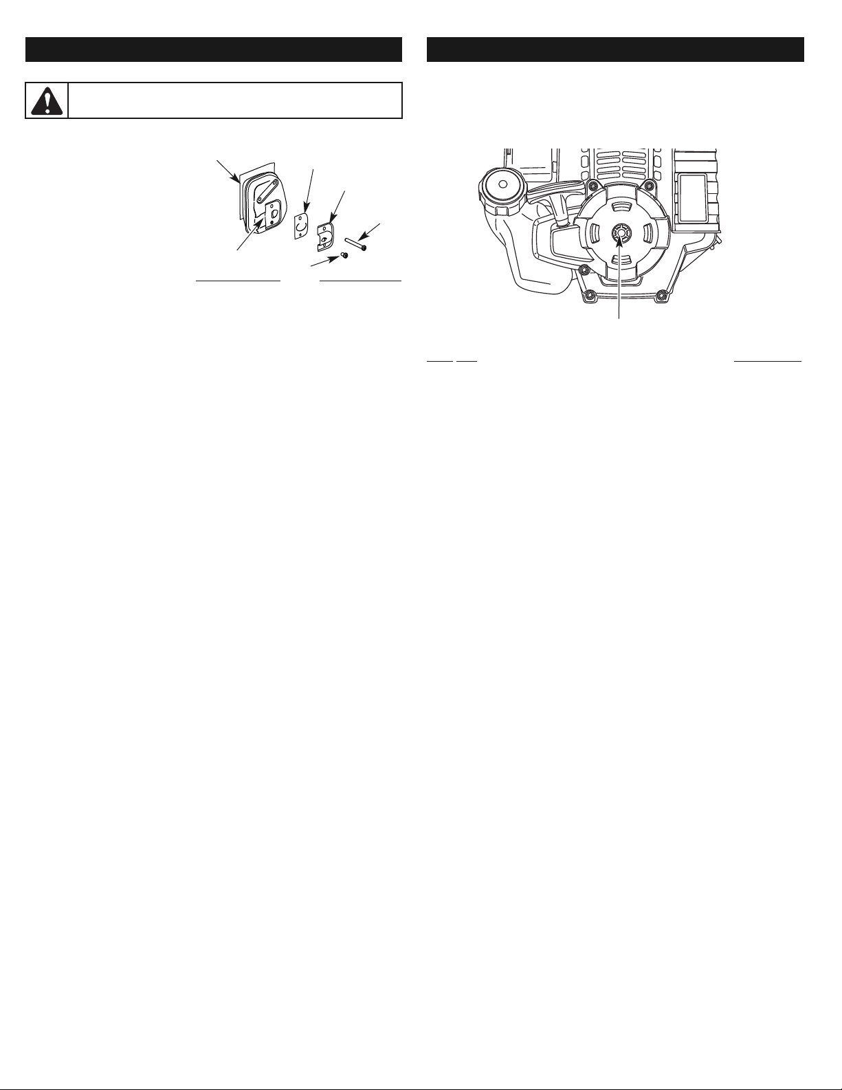
SPARK ARRESTOR MAINTENANCE
1. Remove the engine cover. See Rocker Arm Clearance.
2.
With a flat blade screwdriver or
Torx T-20 bit and a T-25 bit,
remove the screws attaching
the cover to the muffler (Fig. 46).
3. Pull the tab on the cover out
of the muffler and remove the
cover.
4. Remove the spark arrestor
screen from the cover.
5. Clean the spark arrestor
screen with a wire brush or
replace it.
6. Reinstall the spark arrestor screen, cover and screw.
CLEANING
Use a small brush to clean off the outside of the unit. Do not use strong
detergents. Household cleaners that contain aromatic oils such as pine and
lemon, and solvents such as kerosene, can damage plastic housing or handle.
Wipe off any moisture with a soft cloth.
STORAGE
• Never store the unit with fuel in the tank where fumes may reach an open
flame or spark.
• Allow the engine to cool before storing.
• Lock up the unit to prevent unauthorized use or damage.
• Store the unit in a dry, well-ventilated area.
• Store the unit out of the reach of children.
LONG TERM STORAGE
1. Drain all gasoline from the gas tank into a container. Do not use gas that has
been stored for more than 30 days. Dispose of the old gasoline in
accordance to Federal, State, and Local regulations.
2. Start the engine and allow it to run until it stalls. This ensures that all
gasoline has been drained from the carburetor.
3. Allow the engine to cool. Remove the spark plug and put 5 drops of
high quality motor oil into the cylinder. Pull the starter rope slowly to
distribute the oil. Reinstall the spark plug.
NOTE: Remove the spark plug and drain all of the oil from the cylinder
before attempting to start the trimmer after storage.
4. Change the oil, referring to Changing the Oil. Dispose of the old oil in
accordance to Federal, State and Local regulations.
5. Thoroughly clean the unit and inspect for any loose or damaged parts.
Repair or replace damaged parts and tighten loose screws, nuts or
bolts. The unit is ready for storage.
TRANSPORTING
• Allow the engine to cool before transporting.
• Secure the unit while transporting.
• Drain the gas tank before transporting.
• Tighten gas cap before transporting.
T-20 Screw
Fig. 46
T-25
Screw
Cover
Spark Arrestor
Screen
Muffler
Slot
WARNING:
To avoid serious personal injury, always turn the
unit off and allow it to cool before cleaning or servicing it.
PLUG-IN POWER START AND POWER BIT START FEATURES
This unit is designed to be started with an optional Plug-In Power Start or
Power Bit Start that are sold separately. If choosing to start the unit using
one of these features or have questions please contact your local retailer or
call 1-800-4-MY-HOME®, for more information and purchasing. You may
also go to www.craftsman.com.
Electric Start Feature
OPTIONAL EQUIPMENT
Item No. Description
316.85951 . . . . . . . . . . . . . . . . . . . . . . . . . . . . . . . . . . . . . .Plu-In Power Start
316.85952 . . . . . . . . . . . . . . . . . . . . . . . . . . . . . . . . . . . . . . . .Power Start Bit
Page 12

Cutting attachment bound with grass Stop the engine and clean cutting attachment
Cutting attachment out of line Refill with new line
Inner reel bound up Replace the inner reel
Cutting head dirty Clean inner reel and outer spool
Line welded Disassemble, remove the welded section and rewind
Line twisted when refilled Disassemble and rewind the line
Not enough line is exposed
Push the bump head and pull out line until 4 inches (102 mm) of line is
outside of the cutting attachment
Oil, cleaner or lubricant in cutting head Clean and thoroughly dry the cutting head
Old fuel Drain gas tank and add fresh fuel
Cutting attachment bound with grass Stop the engine and clean the cutting attachment
Dirty air filter Clean or replace the air filter
Plugged spark arrestor Clean or replace spark arrestor
Old fuel Drain gas tank and add fresh fuel
Fouled spark plug Replace or clean the spark plug
Plugged spark arrestor Clean or replace spark arrestor
Empty fuel tank Fill fuel tank with fuel
Primer bulb wasn't pressed enough Press primer bulb fully and slowly 10 times
Old fuel Drain gas tank and add fresh fuel
Fouled spark plug Replace or clean the spark plug
Plugged spark arrestor Clean or replace spark arrestor
Air filter is plugged Replace or clean the air filter
Old fuel Drain gas tank and add fresh fuel
Improper idle speed Adjust according to the Idle Speed Adjustments section.
PROBLEM SOLUTION
NEED MORE HELP?
You’ll find the answer and more on managemyhome.com – for free!
■
Find this and all your other product manuals online.
■
Get answers from our team of home experts.
■
Get a personalized maintenance plan for your home.
■
Find information and tools to help with home projects.
brought to you by Sears
ENGINE WILL NOT START
ENGINE WILL NOT IDLE
ENGINE WILL NOT ACCELERATE
ENGINE LACKS POWER OR STALLS WHEN CUTTING
TROUBLESHOOTING
CUTTING ATTACHMENT WILL NOT ADVANCE LINE
CUTTING LINE ADVANCES UNCONTROLLABLY
12
Page 13

13
SPECIFICATIONS
ENGINE*
Engine Type . . . . . . . . . . . . . . . . . . . . . . . . . . . . . . . . . . . . . . . . . . . . . . . . . . . . . . . . . . . . . . . . . . . . . . . . . . . . . . . . . . . . . . . . . . . . . . . . . . Air-Cooled, 4-Cycle
Displacement . . . . . . . . . . . . . . . . . . . . . . . . . . . . . . . . . . . . . . . . . . . . . . . . . . . . . . . . . . . . . . . . . . . . . . . . . . . . . . . . . . . . . . . . . . . . . . . . . . . 1.5 cu. in. (25 cc)
Operating RPM . . . . . . . . . . . . . . . . . . . . . . . . . . . . . . . . . . . . . . . . . . . . . . . . . . . . . . . . . . . . . . . . . . . . . . . . . . . . . . . . . . . . . . . . . . . . . . . . . 6,800 - 9,300 rpm
Idle Speed RPM . . . . . . . . . . . . . . . . . . . . . . . . . . . . . . . . . . . . . . . . . . . . . . . . . . . . . . . . . . . . . . . . . . . . . . . . . . . . . . . . . . . . . . . . . . . . . . . . 2,800 - 3,600 rpm
Ignition Type . . . . . . . . . . . . . . . . . . . . . . . . . . . . . . . . . . . . . . . . . . . . . . . . . . . . . . . . . . . . . . . . . . . . . . . . . . . . . . . . . . . . . . . . . . . . . . . . . . . . . . . . . . Electronic
Ignition Switch . . . . . . . . . . . . . . . . . . . . . . . . . . . . . . . . . . . . . . . . . . . . . . . . . . . . . . . . . . . . . . . . . . . . . . . . . . . . . . . . . . . . . . . . . . . . . . . . . . . . . Rocker Switch
Valve clearance . . . . . . . . . . . . . . . . . . . . . . . . . . . . . . . . . . . . . . . . . . . . . . . . . . . . . . . . . . . . . . . . . . . . . . . . . . . . . . . . . . . . 0.003–0.006 in. (0.076–0.152 mm)
Spark Plug Gap . . . . . . . . . . . . . . . . . . . . . . . . . . . . . . . . . . . . . . . . . . . . . . . . . . . . . . . . . . . . . . . . . . . . . . . . . . . . . . . . . . . . . . . . . . . . . 0.025 inch (0.635 mm)
Lubrication . . . . . . . . . . . . . . . . . . . . . . . . . . . . . . . . . . . . . . . . . . . . . . . . . . . . . . . . . . . . . . . . . . . . . . . . . . . . . . . . . . . . . . . . . . . . . . . . . . . . . . . . . . . SAE 30 Oil
Crankcase Oil Capacity . . . . . . . . . . . . . . . . . . . . . . . . . . . . . . . . . . . . . . . . . . . . . . . . . . . . . . . . . . . . . . . . . . . . . . . . . . . . . . . . . . . . . . . . . . . . . . 2.2 oz (60 ml)
Fuel . . . . . . . . . . . . . . . . . . . . . . . . . . . . . . . . . . . . . . . . . . . . . . . . . . . . . . . . . . . . . . . . . . . . . . . . . . . . . . . . . . . . . . . . . . . . . . . . . . . . . . . . . . . . . . . . . Unleaded
Carburetor. . . . . . . . . . . . . . . . . . . . . . . . . . . . . . . . . . . . . . . . . . . . . . . . . . . . . . . . . . . . . . . . . . . . . . . . . . . . . . . . . . . . . . . . . . . . . . . . . Diaphragm, All-Position
Starter. . . . . . . . . . . . . . . . . . . . . . . . . . . . . . . . . . . . . . . . . . . . . . . . . . . . . . . . . . . . . . . . . . . . . . . . . . . . . . . . . . . . . . . . . . . . . . . . . . . . . . . . . . . . . Auto Rewind
Muffler . . . . . . . . . . . . . . . . . . . . . . . . . . . . . . . . . . . . . . . . . . . . . . . . . . . . . . . . . . . . . . . . . . . . . . . . . . . . . . . . . . . . . . . . . . . . . . . . . . . . . . . . Baffled with Guard
Throttle. . . . . . . . . . . . . . . . . . . . . . . . . . . . . . . . . . . . . . . . . . . . . . . . . . . . . . . . . . . . . . . . . . . . . . . . . . . . . . . . . . . . . . . . . . . . . . . . . . . . . Manual Spring Return
Fuel Tank Capacity . . . . . . . . . . . . . . . . . . . . . . . . . . . . . . . . . . . . . . . . . . . . . . . . . . . . . . . . . . . . . . . . . . . . . . . . . . . . . . . . . . . . . . . . . . . . . . . . . 12 oz (355 ml)
Drive Shaft Housing . . . . . . . . . . . . . . . . . . . . . . . . . . . . . . . . . . . . . . . . . . . . . . . . . . . . . . . . . . . . . . . . . . . . . . . . . . . . . . . . . . . . . . . . . . . . . . . . Aluminum Tube
Throttle Control. . . . . . . . . . . . . . . . . . . . . . . . . . . . . . . . . . . . . . . . . . . . . . . . . . . . . . . . . . . . . . . . . . . . . . . . . . . . . . . . . . . . . . . . . Finger-Tip Trigger w/Lockout
Approximate Unit Weight (No fuel, with Hassle Free®, shield, and D-handle) . . . . . . . . . . . . . . . . . . . . . . . . . . . . . . . . . . . . . . . . . . . . . . . . . . . . 13 lbs (4.6 kg)
Trimmer Head. . . . . . . . . . . . . . . . . . . . . . . . . . . . . . . . . . . . . . . . . . . . . . . . . . . . . . . . . . . . . . . . . . . . . . . . . . . . Hassle Free™ PLUS Head or Rapid Rewind™
Trimming Line . . . . . . . . . . . . . . . . . . . . . . . . . . . . . . . . . . . . . . . . . . . . . . . . . . . . Hassle Free™ XTRA QUIET Spiral Line or 0.095 in (2.41 mm) trimmer line**
DRIVE SHAFT & TRIMMER ATTACHMENT*
* All specifications are based on the latest product information available at the time of printing. We reserve the right to make changes at any time without
notice.
** Dependant on which trimmer head being used. DO NOT use 0.095in (2.41 mm) trimmer line in the Hassle Free™ PLUS cutting head.
REPAIR PROTECTION AGREEMENTS
Congratulations on making a smart purchase. Your new Craftsman
®
Professional product is designed and manufactured for years of dependable operation. But
like all products, it may require repair from time to time. That’s when having a Repair Protection Agreement can save you money and aggravation.
Here is what the Repair Protection Plan Agreement includes:
R Expert service by our 10,000 professional repair specialists
R Unlimited service and no charge for parts and labor on all covered repairs
R Product replacement up to $1500 if your covered product can not be fixed
R Discount of 10% from regular price of service and related installed parts not covered by the agreement; also, 10% off regular price of
preventive maintenance checks
R Fast help by phone – we call it Rapid Resolution - phone support from a Sears representative. Think of us as a “talking owner’s
manual.”
Once you purchase the Agreement, a simple phone call is all that it takes for you to schedule service. You can call anytime day or night, or schedule a service
appointment online.
The Repair Protection Agreement is a risk-free purchase. If you cancel for any reason during the product warranty period, we will provide a full refund. Or a prorated
refund anytime after the product warranty period expires. Purchase you Repair Protection Agreement today!
Some limitations and exclusions apply. For prices and additional information call 1-800-827-6655.
*Coverage in Canada varies on some items. For full details call Sears Canada at 1-800-361-6665.
Sears Installation Service
For Sears professional installation of home appliances, garage door openers, water heaters, and other major home items, in the U.S.A. or Canada call 1-800-
4-MY-HOME
®
.
Page 14

14
NOTES
Page 15
¡Comienzo enchufable de la energía o Comienzo del
pedacito de energía opcional!
Esta unidad tiene un método de comienza que se vende por separado y en muchos casos es
mas facil que jalar una cuerda. Para más información, entre en contacto con un local Craftsman
enchufe o vaya a www.craftsman.com
Sears, Roebuck and Co., Hoffman Estates, IL 60179, U.S.A.
Visite nuestro sitio web: www.craftsman.com
PRECAUCION: Lea el manual
del operador y siga todas las
advertencias e instrucciones
de seguridad.
Manual del Operador
4 Ciclos
RECORTADOR de GASOLINA
Modélo No. 316.792021
• SEGURIDAD
• MONTAJE
• FUNCIONAMIENTO
• MANTENIMIENTO
• LISTADO DE PIEZAS
P/N 769-05876 P02 4/10
PARA RESPUESTAS A PREGUNTAS ACERCA DE ESTE PRODUCTO, LLAMADA 1-800-4-MY-HOME®
®
Page 16
16
• IMPORTANTE INFORMACION DE SEGURIDAD •
LEA TODAS LAS INSTRUCCIONES ANTES DE LA OPERACION
• Lea todas las instrucciones con cuidado. Conozca bien los controles y el uso
correcto de la unidad.
• No opere esta unidad si está cansado, enfermo, o bajo los efectos del
alcohol, drogas o medicamentos.
• Los niños y los adolescentes menores de 15 años no deben operar las
unidades, excepto por los adolescentes guiados por un adulto.
• Inspeccione la unidad antes de utilizarla. Cambie las partes dañadas.
Verifique si existen pérdidas de combustible. Asegúrese de que los
sujetadores estén bien colocados y asegurados. Cambie las partes
accesorias de corte que estén quebradas, cascadas o dañadas de cualquier
forma. Asegúrese de que el accesorio de corte está bien instalado y ajustado
con firmeza. Asegúrese de que la protección accesoria de corte esté bien
conectada y colocada según se recomienda.
• No use nunca línea reforzada con metal, alambre, cadena ni soga, etc. Estas
pueden desprenderse y convertirse en un proyectil peligroso.
• Oprima el control del regulador y verifique que regrese automáticamente a la
posición de mínima. Haga todos los ajustes o reparaciones antes de usar la
unidad.
•
Limpie el área de corte antes de cada uso. Retire todos los objetos como rocas,
vidrios rotos, clavos, alambre o cuerda los cuales pueden ser despedidos o
enredarse en el accesorio de corte. Aleje a todos los niños, espectadores y
animales domésticos. Mantenga todos los niños, espect-adores y animales
domésticos a un radio de por lo menos 15 m (50 pies); aún así puede existir un
riesgo de objetos despedidos contra los espectadores. Los espectadores
deben usar protección para sus ojos. Si alguien se le acerca, pare el motor y el
accesorio de corte de inmediato.
• Use solamente líneas de repuesto de fabricantes de equipos originales de
Líneas en Espiral Hassle-Free™ XTRA QUIET de Craftsman. Nunca use
líneas reforzadas con metal, alambre o soga. Estas pueden desprenderse y
convertirse en proyectiles peligrosos.
• Oprima el control del regulador y compruebe que regresa automáticamente a
la posición de marcha en vacío. Haga todos los ajustes o reparaciones antes
de usar la unidad.
ADVERTENCIAS DE SEGURIDAD PARA LOS RECORTADORES A GASOLINA
• Guarde el combustible en envases que hayan sido diseñados y aprobados
para el almacenamiento de dichos materiales.
•
Aleje la unidad a por lo menos 9.1 m (30 pies), del lugar de carga de
combustible antes de arrancar el motor. No fume, mantenga las chispas y las
llamas abiertas lejos del área mientras carga el combustible u opera la unidad.
• Cargue el combustible en un área exterior bien ventilada donde no haya
chispas ni llamas. Quite lentamente la tapa del combustible sólo después de
apagar el motor. No fume mientras carga el combustible. Limpie de inmediato
todo el combustible que se haya derramado.
• Antes de llenar el tanque de combustible, apague siempre el motor y espere
que se enfríe. No retire nunca la tapa del tanque de combustible ni cargue
combustible mientras el motor esté caliente. No opere nunca la unidad sin la
tapa del combustible colocada firmemente en su lugar. Afloje la tapa del
combustible lentamente para disipar la presión del tanque.
• Evite crear una fuente de encendido por combustible derramado. No
arranque el motor hasta que se hayan disipado los vapores del combustible.
DURANTE LA OPERACION
• No arranque ni opere la unidad en una sala o edificio cerrado. Los gases de
escape de monóxido de carbono pueden ser letales en un área cerrada.
Opere esta unidad sólo en un área exterior bien ventilada.
• Use lentes o gafas de protección que cumplan con las normas ANSI Z87.11989, y protección para sus oídos/audición mientras opere esta unidad. Use
siempre una máscara facial o para protegerse contra el polvo si la operación
levanta polvo.
• Use pantalones largos y gruesos, botas, guantes y camisa de manga larga.
No use ropa holgada, alhajas, pantalones cortos, sandalias ni esté descalzo.
Sostenga el cabello sobre el nivel de los hombros.
Toda la información, las ilustraciones y las especificaciones contenidas en este
manual se basan en la información más reciente disponible en el momento de
impresión del manual. Nos reservamos el derecho de hacer cambios en
cualquier momento sin aviso previo.
INDICE DE CONTENIDOS
Normas para una operación segura . . . . . . . . . . . . . . . . . . . . . . . . . . . . . .16
Garantía . . . . . . . . . . . . . . . . . . . . . . . . . . . . . . . . . . . . . . . . . . . . . . . . . . .18
Conozca su unidad . . . . . . . . . . . . . . . . . . . . . . . . . . . . . . . . . . . . . . . . . . .18
Instrucciones de ensamble . . . . . . . . . . . . . . . . . . . . . . . . . . . . . . . . . . . . .18
Información del aceite y del combustible . . . . . . . . . . . . . . . . . . . . . . . . . .19
Instrucciones de arranque y apagado . . . . . . . . . . . . . . . . . . . . . . . . . . . .20
Instrucciones de operación . . . . . . . . . . . . . . . . . . . . . . . . . . . . . . . . . . . .20
Instrucciones de mantenimiento y reparación . . . . . . . . . . . . . . . . . . . . . .21
Limpieza y almacenamiento . . . . . . . . . . . . . . . . . . . . . . . . . . . . . . . . . . . .25
Resolución de problemas . . . . . . . . . . . . . . . . . . . . . . . . . . . . . . . . . . . . . .26
Especificaciones . . . . . . . . . . . . . . . . . . . . . . . . . . . . . . . . . . . . . . . . . . . . .27
Lista de piezas . . . . . . . . . . . . . . . . . . . . . . . . . . . . . . . . . . . . . . . . . . . . . .30
Numeros de servicio . . . . . . . . . . . . . . . . . . . . . . . . . . . . . . . .Contraportada
NORMAS PARA UNA OPERACION SEGURA
PARACHISPAS
NOTA: Para los usuarios en tierras forestales de los EE.UU. y en los estados de
California, Maine, Oregon y Washington. Todos los terrenos forestales de los EE.UU.
y el estado de California (Códigos de Recursos Públicos 4442 y 4443), Oregon y
Washington, requieren por decreto, que ciertos motores de combustión interna que se
hagan funcionar en zonas boscosas y/o zonas cubiertas por pastizales, estén equipados
con un parachispas, que sean mantenidos en buen estado de funcionamiento o que el
motor sea construido, esté equipado y sea mantenido para evitar incendios. Consulte los
reglamentos pertinentes a esos requisitos con las autoridades estatales o locales. El
incumplimiento de esos requisitos puede responsabilizarle o someterle a la imposición de
una multa. Esta unidad fue equipada en la fábrica con un parachispas. Si requiere
sustitución, hay una Pantalla Parachispas disponible, Pieza # 753-06334 al contactar el
departamento de servicio.
PROPOSICIÓN 65 DE CALIFORNIA
ADVERTENCIA
LAS EMISIONES DEL MOTOR DE ESTE PRODUCTO CONTIENEN
SUBSTANCIAS QUIMICAS QUE EL ESTADO DE CALIFORNIA CONOCE
COMO CAUSANTES DECANCER, DEFECTOS DE NACIMIENTO U OTROS
DAÑOS REPRODUCTIVOS.
NOTA:
¡Esta unidad puede utilizar un comienzo enchufable de la energía o un
accesorio de arranque opcional comienzo del pedacito de energía!
Para informarse sobre el uso adecuado de estos sistemas, consulte el
manual del operador del comienzo enchufable de la energía de opcional
comienzo del pedacito de energía. (Se vende por separado) En la página 25
de este manual encontrará la información necesaria para comprar estos
accesorios).
Lea el manual del operador y siga todas las advertencias e instrucciones
de seguridad. De no hacerlo, el operador y/o los espectadores pueden sufrir
graves lesiones. SI TIENE PREGUNTAS, LLAME AL 1-800-4-MY-HOME®
SIMBOLO SIGNIFICADO
ADVERTENCIA:
El no seguir una advertencia de seguridad puede
conducir a que usted u otras personas sufran lesiones. Siga siempre las
precauciones de seguridad para reducir el riesgo de incendio, descarga
eléctrica y lesiones personales.
PRECAUCIÓN:
El no seguir una advertencia de seguridad
puede conducir a daño patrimonial o a que usted u otras personas
sufran lesiones personales. Siga siempre las precauciones de
seguridad para reducir el riesgo de incendio, descarga eléctrica y
lesiones personales.
Los símbolos de seguridad se utilizan para llamar su atención sobre posibles
peligros. Los símbolos de seguridad y sus explicaciones merecen toda su atención
y comprensión. Los símbolos de seguridad no eliminan ningún peligro por sí
mismos. Las instrucciones o advertencias que ofrecen no substituyen las medidas
adecuadas de prevención de accidentes.
ALERTA DE SEGURIDAD:
Indica peligro, advertencia o
precaución. Debe prestar atención para evitar sufrir graves lesiones
personales. Puede ser utilizado junto con otros símbolos o figuras.
NOTA: Le ofrece información o instrucciones que son esenciales para la
operación o mantenimiento del equipo.
PELIGRO:
El no obedecer una advertencia de seguridad puede
conducir a que usted u otras personas sufran graves lesiones. Siga
siempre las precauciones de seguridad para reducir el riesgo de
incendio, descarga eléctrica y lesiones personales.
ADVERTENCIA:
La gasolina es muy inflamable y sus gases pueden
explotar si se encienden. Tome las siguientes precauciones:
AVERTISSEMENT:
Lorsque vous utilisez la machine, vous devez
suivre les consignes de sécurité. Veuillez lire ces instructions avant
d’opérer la machine pour vous assurer de la sécurité de l’opérateur et de
tout spectateur. Veuillez conserver ces instructions pour un usage ultérieur.
Page 17
17
NORMAS PARA UNA OPERACION SEGURA
• La protección accesoria de corte debe estar siempre colocada en su lugar
mientras opere la unidad. No opere la unidad con las dos líneas de corte
extendidas, y la línea correcta instalada. No extienda la línea de corte más allá
de la longitud de la protección.
• Esta unidad cuenta con un embrague. El accesorio de corte permanece
estacionario cuando el motor está en marcha lenta. Si no lo hace, haga ajustar
la unidad por un técnico de servicio autorizado.
• Ajuste la manija a su tamaño de modo que le brinde el mejor agarre.
• Asegúrese de que el accesorio de corte no está en contacto con ningún
objeto antes de arrancar la unidad.
• Use la unidad únicamente con la luz del día o con buena luz artificial.
• Evite arrancar la unidad accidentalmente. Colóquese en posición de inicio
siempre que tire de la cuerda de arranque. El operador y la unidad deben estar
en una posición estable al comenzar. Lea las instrucciones de Arranque y
Apagado.
• Use la herramienta adecuada. No use esta unidad para ninguna tarea para la
cual no ha sido diseñada.
• No se estire demasiado. Mantenga siempre una posición y equilibrio
adecuados.
• Sostenga siempre la unidad con ambas manos mientras esté en
funcionamiento. Sostenga con firmeza tanto el mango como la manija auxiliar.
• Mantenga las manos, la cara y los pies lejos de todas las partes móviles. No
intente tocar ni detener el accesorio de corte mientras gira.
• No toque el motor, el bastidor del engranaje ni el silenciador. Estas partes se
calientan mucho con la operación. Luego de apagar la unidad, permanecen
calientes durante un tiempo breve.
• No opere el motor a una velocidad mayor que la necesaria para cortar,
recortar o recortar los bordes. No haga funcionar el motor a alta velocidad
mientras no está cortando.
• Apague siempre el motor cuando demore el corte o mientras camina entre
zonas de corte.
• Si golpea o se enreda con algún objeto extraño, apague el motor de inmediato
y verifique si hay daños. Repare todos los daños antes de volver a intentar
operar la unidad. No opere la unidad si tiene piezas flojas o dañadas.
• Apague el motor para realizar todo el mantenimiento, repara-ciones o cambio
del accesorio de corte u otros accesorios.
• Use sólo piezas y accesorios de repuesto del fabricante del equipo original
para esta unidad. Puede obtenerlos en su proveedor de servicio autorizado. El
uso de piezas y accesorios que no son equipo origina; puede causar graves
lesiones al operador o el daño de su unidad, y la cancelación de su garantía.
• Mantenga la unidad libre de vegetación y otros materiales. Pueden alojarse
entre el accesorio de corte y la protección.
• Para reducir el riesgo de incendio, cambie los silenciadores y amortiguadores
de chispas defectuosos, mantenga el motor y el silenciador libre de pasto,
hojas, grasa excesiva o acumulaciones de carbono.
OTRAS ADVERTENCIAS DE SEGURIDAD
• No guarde nunca la unidad con combustible en el tanque en un edificio donde
los gases puedan llegar a una llama abierta o a una chispa.
• Espere que el motor se enfríe antes de guardar o transportar la unidad.
Asegúrese de que la unidad esté segura al transportarla.
• Guarde la unidad bajo llave en un lugar adecuado y seco para evitar que sea
usada por personas no autorizadas y se dañe, fuera del alcance de los niños.
• Nunca moje ni rocíe la unidad con agua ni con ningún otro líquido. Mantenga
las manijas secas, limpias y sin residuos. Limpie la unidad luego de cada uso,
lea las instrucciones de Limpieza y Almacenamiento.
• Guarde estas instrucciones. Consúltelas con frecuencia y utilícelas para
enseñar a otros usuarios. Si le presta esta unidad a alguien, préstele también
estas instrucciones.
CONSERVE ESTAS INSTRUCCIONES
Este manual del operador describe los símbolos y figuras de seguridad e internacionales que pueden aparecer en este producto. Lea el manual del operador
para obtener información completa acerca de la seguridad, ensamble, operación y mantenimiento y reparación.
• SIMBOLOS DE SEGURIDAD E INTERNACIONALES •
SIMBOLO SIGNIFICADO SIMBOLO SIGNIFICADO
• SIMBOLO DE ALERTA DE SEGURIDAD
Indica peligro, advertencia o precaución. Puede ser utilizado
junto con otros símbolos o figuras.
•
LEA EL MANUAL DEL OPERADOR
ADVERTENCIA: Lea el manual del operador y siga todas
las advertencias e instrucciones de seguridad. De no hacerlo, el
operador y/o los espectadores pueden sufrir graves lesiones.
• USE PROTECCION OCULAR Y AUDITIVA
ADVERTENCIA: Los objetos arrojados por la unidad y el
ruido fuerte pueden causar graves lesiones oculares y
pérdida auditiva. Utilice protección ocular que cumpla con
las normas ANSI Z87.1 y protección auditiva cuando opere
esta unidad. Use una careta completa cuando la necesite.
• COMBUSTIBLE SIN PLOMO
Use siempre combustible limpio, nuevo y sin plomo.
• CONTROL DE ENCENDIDO Y APAGADO
ENCENDIDO /ARRANQUE /MARCHA
• CONTROL DE ENCENDIDO Y APAGADO
APAGADO o PARADO
• DE CALIENTE
ADVERTENCIA: No toque un silenciador ni un cilindro
caliente. Puede quemarse. Estas partes se calientan mucho
con el uso. Luego de apagarse permanecen calientes
durante un corto tiempo.
• MANTENGA ALEJADOS A LOS ESPECTADORES
ADVERTENCIA: Mantenga a todos los espectadores, en
especial a niños y animales domésticos a por lo menos 50
pies (15 m) del área de corte.
• LOS OBJETOS DESPEDIDOS Y LA CUCHILLA ROTATIVA
PUEDEN CAUSAR GRAVES LESIONES
ADVERTENCIA:
No opere esta unidad si la protección
plástica de línea no está colocada en su lugar. Manténgase
alejado del accesorio de corte giratorio.
• BOMBILLA DEL CEBADOR
Oprima la bombilla del cebador completa y lentamente, de 10
veces
• INDICADOR DE ACEITE
Consulte el manual del operador para obtener información acerca
del tipo correcto de aceite.
• CUCHILLA AFILADA
ADVERTENCIA: La protección del accesorio de corte
contiene una cuchilla afilada. Para prevenir graves lesiones,
no toque la cuchilla.
• NO UTILICE COMBUSTIBLE E85 EN ESTA UNIDAD
ADVERTENCIA: Se ha demostrado que el combustible
que contiene más del 15% de etanol probablemente
ocasionará daños al motor y anulará la garantía.
Page 18
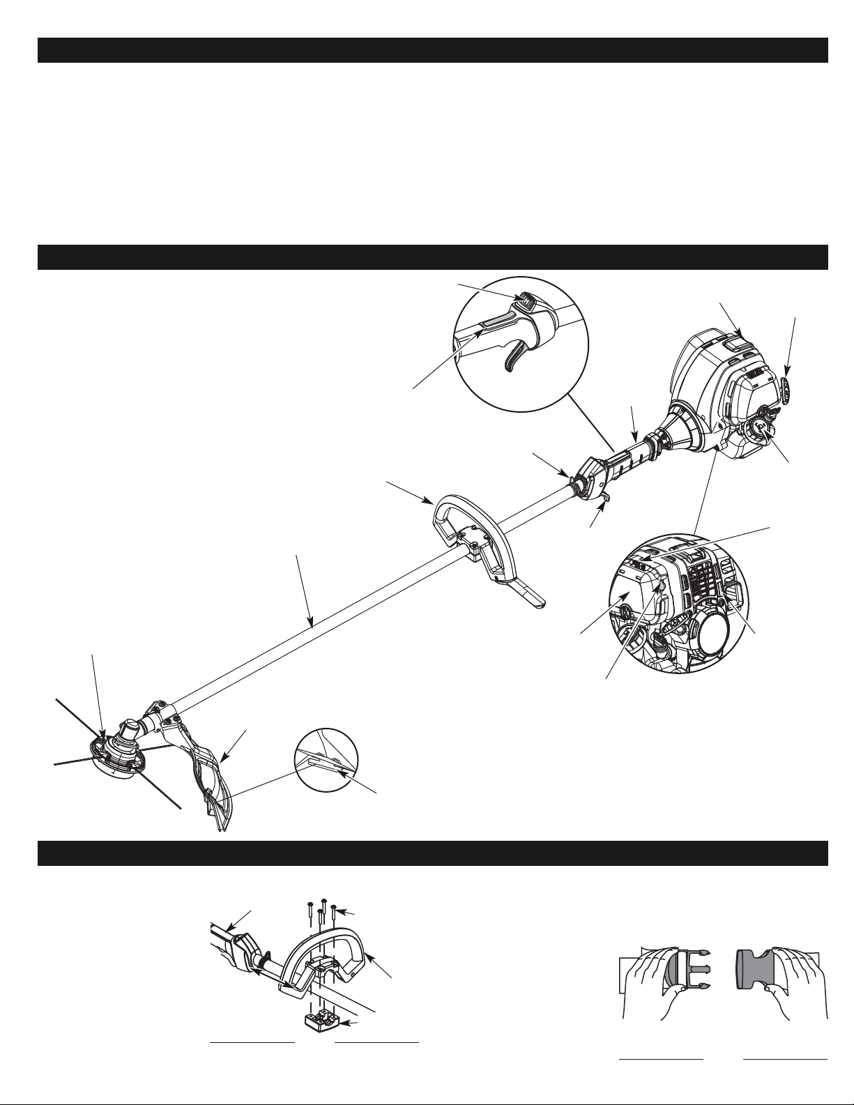
3. Mientras sostiene la unidad en posición de operación (Fig. 13), coloque la
manija en D en la posición que le brinde el mejor agarre.
4. Ajuste los tornillos de la abrazadera en forma pareja hasta que la manija en
D esté firme.
INSTALE LA CORREA DE LOS
HOMBROS
1. Póngase el arnés bien
utilizando la presilla o sobre
la cabeza y sobre el hombro.
(Fig. 2).
Fig. 2
GARANTÍA TOTAL PROFESIONAL DE CRAFTSMAN
Si este producto de Craftsman Professional falla debido a un defecto en el material o en la mano de obra dentro de un período de tres años a partir de la fecha
de compra, devuélvalo a cualquier tienda o Centro de Servicio de Piezas y Reparaciones Sears u otro establecimiento de Craftsman en los Estados Unidos
para que sea reparado sin costo alguno (o ser reemplazado si resulta imposible repararlo).
Esta garantía se aplica solamente durante un año si este producto en algún momento se utiliza para fines comerciales o de alquiler.
Esta garantía abarca SOLAMENTE los defectos en el material o en la mano de obra. Sears NO pagará:
• Los artículos consumibles que se desgasten debido al uso normal dentro del período de garantía.
•
Las reparaciones necesarias debidas a accidente así como por no operar o no mantener el equipo de acuerdo con todas las instrucciones provistas.
• Mantenimiento preventivo, afinaciones del producto, o limpiezas o ajustes de carburadores.
Esta garantía le concede a usted derechos legales específicos, y usted pudiera tener otros derechos que varían de un estado a otro.
Sears, Roebuck and Co., Hoffman Estates, IL 60179
GARANTÍA
CONOZCA SU UNIDAD
INSTRUCCIONES DE ENSAMBLE
18
APLICACIONES
Como recortador:
• Corte de césped y hierbas delgadas
• Recorte de bordes
• Recorte decorativo alrededor de árboles, cercos, etc.
Protección accesoria
de corte
Tapa del
combustible
Manija en D
Accesorio de corte
Hassle Free
®
PLUS
Manjo del
eje
Bastidor del eje
Mango de la
cuerda de
arranque
Gatillo del
regulador
Cubierta del
filtro de aire
Bujía de encendido
Silenciador
Control de encendido y
apagado
Adaptador de
apoyo
Bombilla del
cebador
Cuchilla de corte
de línea
INSTALACIÓN Y AJUSTE DE LA MANIJA EN D
1.
Coloque la manija en D por
encima del bastidor del eje y
sobre la abrazadera inferior
(Fig. 1). Colóquela a un
mínimo de 15.24 cm (6
pulgadas) desde el extremo
del puño del eje.
2. Sostenga cada tuerca
hexagonal en el hueco de la
abrazadera inferior con un
dedo. Inicie los tornillos con un
destornillador grande de pala
o Torx T-25. No los apriete
hasta ajustar la manija.
Tornillos (4)
Mango del eje
Mínimo de
15.24 cm
(6 pulgadas)
Fig. 1
Abrazadera
inferior
Manija en D
Traba del
regulador
Palanca azul del
obturador
Page 19
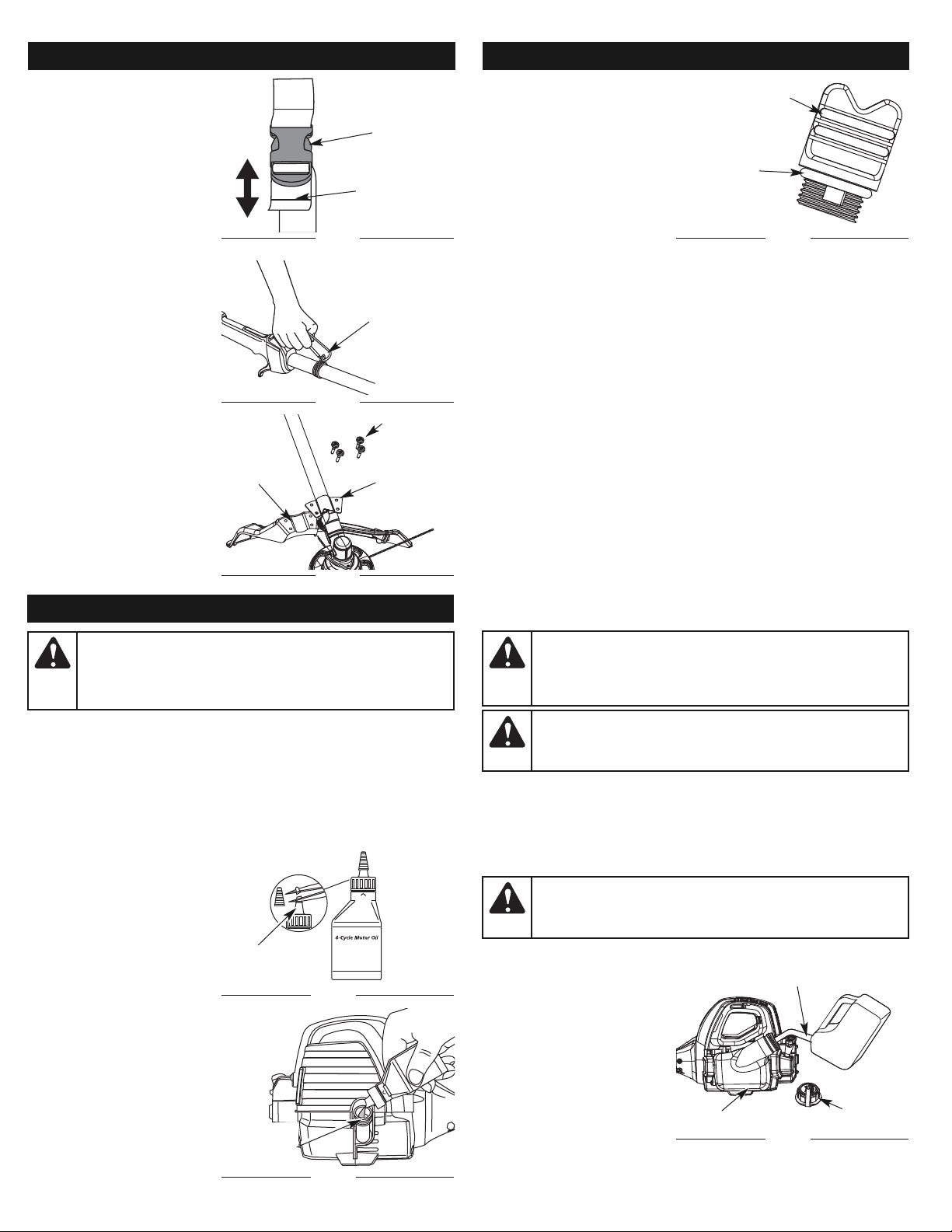
4.
Vierta todo el contenido de la
botella de aceite en el cigüeñal
(Fig. 7).
NOTA: No agregue nunca aceite
al combustible o al
tanque de combustible.
5. Limpie todo el aceite que
pueda haberse derramado y
vuelva a instalar el tapón del
aceite.
No podemos exagerar la importancia
del control y mantenimiento del nivel
correcto de aceite en el cigüeñal.
Verifique el aceite antes de cada uso y cámbielo cuando sea necesario según se
indica en la sección de Cambio del aceite.
TIPO DE COMBUSTIBLE RECOMENDADO
El combustible viejo es la causa principal del mal funcionamiento de la unidad.
Asegúrese de usar combustible nuevo, limpio y sin plomo.
NOTA:
Elimine la gasolina vieja de acuerdo a los reglamentos federales,
estatales y locales.
NOTA: Este es un motor de cuatro ciclos. Para evitar dañar su unidad, no
mezcle el aceite con la gasolina.
Definición de los combustibles de mezcla
Los combustibles actuales con frecuencia son una mezcla de gasolina y uno o más
oxigenantes como el etano, el metanol o el MTBE (éter). El combustible con mezcla
de alcohol absorbe agua. Un porcentaje de agua tan pequeño como el 1% en el
combustible puede hacer que el combustible y el aceite se separen. Se forman
ácidos mientras está guardado. Cuando use combustible con mezcla de alcohol, use
combustible nuevo (almacenado durante menos de 30 días).
Uso de los combustibles de mezcla
Si decide usar un combustible de mezcla o si su uso es inevitable, le
recomendamos que tome las siguientes precauciones:
• Use siempre una mezcla fresca de combustible según lo indica su manual
del operador
• Use el aditivo especial de combustible STA-BIL® o uno similar
• Drene el tanque y haga funcionar el motor en seco antes de guardar la
unidad
Uso de aditivos en el combustible
El uso de aditivos en el combustible, como el estabilizador de gasolina STA-BIL® o
similar, inhibirá la corrosión y reducirá la formación de depósitos de goma. El uso de
aditivos puede evitar que se formen depósitos dañinos en el carburador por hasta
ocho (8) meses. Agregue 23 ml (0.8 de onza) de aditivo por galón de combustible de
acuerdo a las instrucciones del envase. No agregue NUNCA los aditivos
directamente al tanque de combustible de la unidad.
CARGA DE COMBUSTIBLE EN LA UNIDAD
1. Saque la tapa de la gasolina (Fig. 9).
2. Coloque el pico del recipiente
de gasolina en el orificio de
llenado del tanque de gasolina
(Fig. 9) y llene el tanque.
NOTA: No llene el tanque
demasiado.
3.
Limpie toda la gasolina que
pueda haberse derramado
4. Vuelva a instalar la tapa de la
gasolina.
5.
Mueva la unidad por lo menos
9.1 m (30 pies) de la fuente y
sitio de carga antes de arrancar
el motor.
INFORMACION DEL ACEITE Y DEL COMBUSTIBLE
19
TIPO DE ACEITE RECOMENDADO
El uso de un aceite del tipo y peso correctos en el cigüeñal es
extremadamente importante. Verifique el aceite antes de cada uso y cambie
el aceite con frecuencia. Si no usa el aceite correcto, o utiliza aceite sucio,
puede causar el desgaste y falla prematuros del motor. Uso un aceite de
buena calidad SAE 30 de API (American Petroleum Institute) clase de servicio
SG, SF, SH.
CARGA DE ACEITE EN EL CARTER DEL CIGÜEÑAL: USO INICIAL
NOTA:
Esta unidad se envía sin
carga de aceite. A fin de
evitar el daño de la unidad,
cargue aceite en el cárter
del cigüeñal antes de
intentar arrancar la unidad.
Su unidad trae una botella de
aceite SAE 30 SF, SG, SH de 60 ml
(2.2 fl.oz.) (Fig. 6).
NOTA: Guarde la botella para
medir la cantidad correcta
de aceite cuando deba
cambiarlo en el futuro.
Lea Cambio de Aceite.
1. Desenrosque la tapa de la
botella de aceite y retire el
sello de papel que cubre la
apertura. Vuelva a colocar la
tapa. Corte la punta de la
boquilla del embudo (Fig. 6).
2. Coloque la unidad sobre una
superficie plana.
3. Saque el tapón de aceite del
cigüeñal (Fig. 8).
ADVERTENCIA:
EL LLENAR DEMA- SIADO EL CÁRTER PUEDE
CAUSAR LESIONES PERSONALES GRAVES No podemos exagerar la
importancia del control y mantenimiento del nivel correcto de aceite en
el cigüeñal. Verifique el aceite antes de cada uso y cámbielo cuando
sea necesario según se indica en la sección de Cambio del aceite.
Boquilla del
embudo
Fig. 6
Anillo en
“O”
Tapón de aceite
Fig. 8
2. Ajústela levantándola
ligeramente en la parte
posterior de la presilla
inferior, empuje o tire del
extremo suelto de la correa
para adaptarla al tamaño y
comodidad del operador.
(Fig. 3).
3.
Fije la presilla de los hombros a
la unidad. (Fig. 4)
INSTALACIÓN DEL
PROTECTOR DEL CABEZAL DE
CORTE
1. Coloque el protector del
cabezal de corte en el
soporte de montaje de
protección, asegurándose de
alinear los orificios en el
protector con los del soporte
de montaje de protección.
(Fig. 5)
2. Tome los 4 tornillos del
protector y atornille cada uno
en el protector hasta que
quede apretado con la mano.
3. Utilizando un destornillador
de cabeza plana o T-20,
apriete los tornillos hasta que
el protector quede firme en
su lugar. (Fig. 5)
Fig. 3
Fig. 4
Fig. 5
Clip de
Apoyo
Etiqueta de
ajuste
Adaptador
de apoyo
Soporte de
montaje de
protección
Protector
accesorio
de corte
Tornillos (4)
INFORMACION DEL ACEITE Y DEL COMBUSTIBLEINSTRUCCIONES DE ENSAMBLE
ADVERTENCIA:
Cargue el combustible en un área exterior limpia
y bien ventilada. Limpie de inmediato todo combustible que se haya
derramado. Evite crear una fuente de encendido con el combustible
derramado. No arranque el motor hasta que se hayan evaporado los
gases del combustible.
ADVERTENCIA:
La gasolina es muy inflamable. Los gases pueden
explotar si se encienden. Apague siempre el motor y espere que se enfríe
antes de cargar el tanque de combustible. No fume mientras llena el
tanque. Mantenga las chispas y las llamas lejos del área.
Orificio de
llenado de
aceite
Fig. 7
ADVERTENCIA:
Saque la tapa del combustible lentamente
para evitar lesionarse con el rociado del combustible. No opere
nunca la unidad sin la tapa del combustible firmemente colocada
en su lugar.
Tapa del
combustible
Tanque de gasolina
Fig. 9
Inyector del envase del gas
Page 20
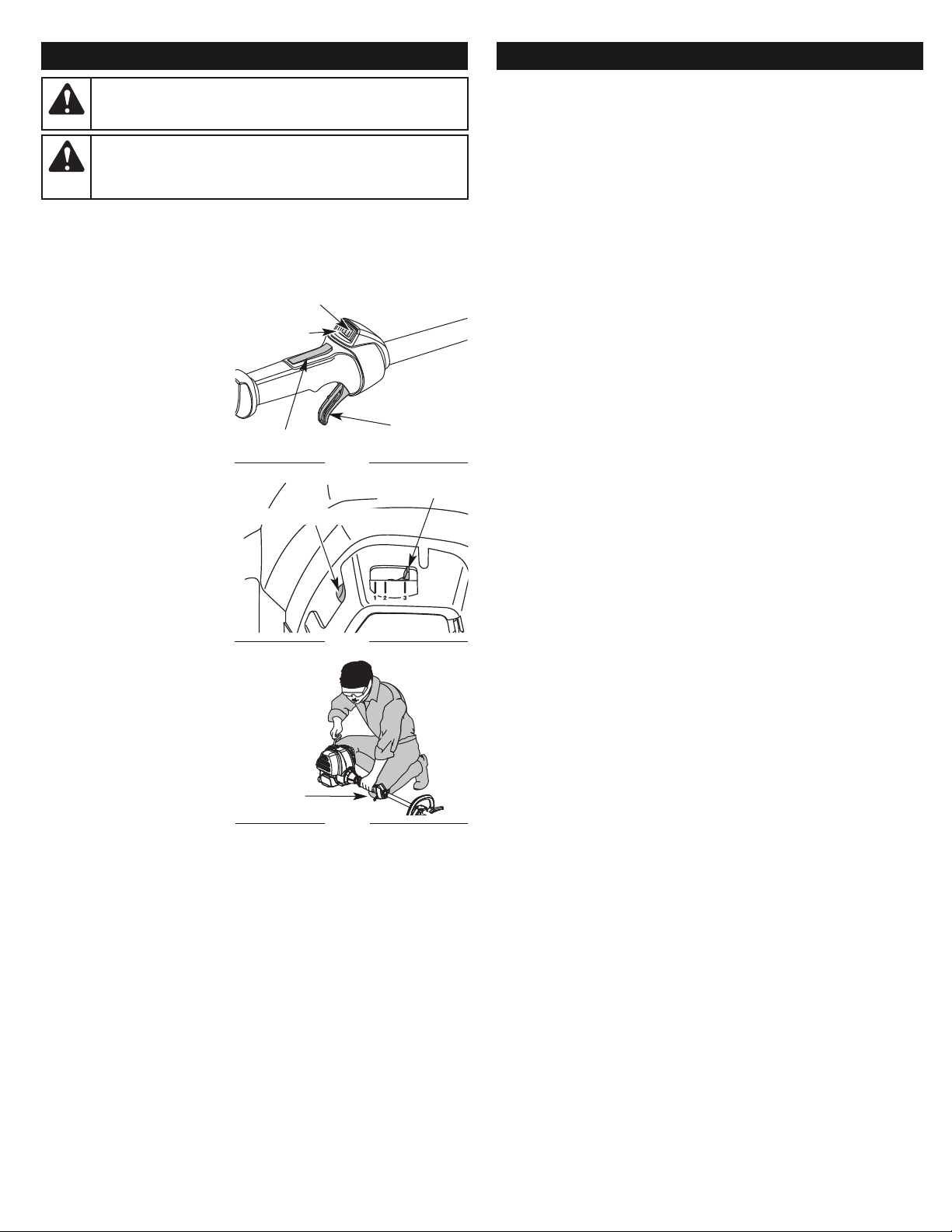
20
INSTRUCCIONES DE ARRANQUE Y APAGADO
ADVERTENCIA:
Use esta unidad sólo en un área exterior bien
ventilada. Los gases de escape de monóxido de carbono pueden
ser letales en un área cerrada.
ADVERTENCIA:
Evite los arranques accidentales. Colóquese en
posición de inicio cuando tire de la cuerda de arranque (Fig. 12). El
operador y la unidad deben estar en una posición estable al arrancar
la unidad para evitar graves lesiones personales.
NOTA:
Esta unidad utiliza el sistema de arranque Incredi-Pull™, que reduce
notablemente el esfuerzo necesario para arrancar el motor. No hay
resistencia fuerte al tirar de la cuerda de arranque. Esté consciente de que
este método de arranque es muy diferente (y mucho más fácil) que los
métodos de arranque anteriores.
INSTRUCCIONES DE ARRANQUE
1.
Verifique el nivel de aceite en el
cárter del cigüeñal. Lea
Inspección del Nivel de Aceite.
2. Llene el tanque de
combustible con gasolina
nueva, limpia y sin plomo.
NOTA:
No hay necesidad de
encender la unidad. El
Control de Parada
Arranque y Apagado está
en la posición Arranque (I),
en todo momento (Fig. 10).
3.
Oprima completamente el
cebador y suéltelo 10 veces.
Hágalo lentamente. Se deberá
ver un poco de combustible en
el cebador y en las tuberías de
alimentación de combustible
(Fig. 11). Si no puede ver el
combustible en el cebador,
oprímalo y suéltelo tantas
veces como sea necesario
hasta que vea combustible en
el mismo.
4. Coloque la palanca del
obturador en Posición 1
(Fig. 11).
5. Agáchese en posición de
arranque (Fig. 12). Oprima la
traba del regulador hacia
adentro y apriete la palanca de
control del regulador. Hale el
cordón de arranque 5 veces.
6. Coloque la palanca del
obturador en Posición 2
(Fig. 11).
7. Mientras oprime la traba del
regulador hacia adentro y
aprieta el control del
regulador, hale el cordón de arranque de 1 a 4 veces, para arrancar el
motor.
8. Mantenga oprimido el regulador y deje que el motor se caliente durante
30 a 60 segundos.
9. Mantenga apretado el control del regulador, ponga la palanca del
obturador en la Posición 3 (Fig. 11) y haga funcionar la unidad durante
60 segundos más. La unidad se puede usar durante este paso.
NOTA:
La unidad se ha calentado debidamente cuando el motor acelera sin fallar.
SI... el motor funciona con fallas, vuelva a colocar la palanca del
obturador en la Posición 2 (Fig. 11) y continúe calentando el motor.
SI... el motor no arranca, regrese al paso 3.
SI...
el motor no arranca después de unos cuantos intentos, coloque la
palanca del obturador en la Posición 3, y oprima el gatillo. Apriete y
mantenga apretado el botón de ENCENDIDO (I) del arrancador eléctrico
o taladro a intervalos de 2 segundos hasta que la unidad arranque.
SI ESTÁ CALIENTE... Si el motor ya está caliente, arranque la unidad con la
palanca azul del obturador en la Posición 2. Después que la unidad
arranque, mueva la palanca azul del obturador a la Posición 3.
INSTRUCCIONES DE APAGADO
1. Saque la mano del control del regulador. Deje enfriar el motor en
marcha en vacío.
2. Oprima y mantenga oprimido el control de encendido y apagado en la
posición de APAGADO (O) hasta que el motor se detenga por completo
(Fig. 10).
Arranque (I)
Apagado (O)
Control del
regulador
Fig. 10
Posición de
Arranque
Control del
regulador
Fig. 12
INSTRUCCIONES DE ARRANQUE Y APAGADO
Traba del regulador
Palanca del obturador
Fig. 11
Bombilla del cebador
NOTA:
¡Esta unidad puede utilizar un comienzo enchufable de la energía o un
accesorio de arranque opcional comienzo del pedacito de energía!
Para informarse sobre el uso adecuado de estos sistemas, consulte el
manual del operador del comienzo enchufable de la energía de opcional
comienzo del pedacito de energía. (Se vende por separado) En la página 25
de este manual encontrará la información necesaria para comprar estos
accesorios).
INSTRUCCIONES DE ARRANQUE
1. Verifique el nivel de aceite en el cárter del cigüeñal. Lea Inspección del
Nivel de Aceite.
2. Llene el tanque de combustible con gasolina nueva, limpia y sin plomo.
NOTA:
No hay necesidad de encender la unidad. El Control de Parada
Arranque y Apagado está en la posición Arranque (I), en todo momento
(Fig. 10).
3.
Oprima completamente el cebador y suéltelo 10 veces. Hágalo lentamente.
Se deberá ver un poco de combustible en el cebador y en las tuberías de
alimentación de combustible (Fig. 11). Si no puede ver el combustible en el
cebador, oprímalo y suéltelo tantas veces como sea necesario hasta que vea
combustible en el mismo.
4. Coloque la palanca del obturador en Posición 1 (Fig. 11).
5. Crouch in the starting position (Fig. 12).Place the electric starter or
power start bit into the back of the unit. Refer to the Operation section
of the Electric Starter or Power Start Bit™ operator’s manual.
6. Presione el cierre de la válvula reguladora adentro y exprima
completamente la palanca de mando de válvula reguladora. Presione y
sostenga el arranque eléctrico o perfore ARRANQUE (I) el botón por 2
segundos.
7. Coloque la palanca del obturador en Posición 2 (Fig. 11).
8. Mientras que presiona el cierre de la válvula reguladora adentro y
exprime el control de válvula reguladora, presione y sostenga el
arranque eléctrico o perfore ARRANQUE (I) el botón para 2 segundos
intervalos hasta que la unidad comience.
9. Continúe exprimiendo el control de válvula reguladora, quitando el
arranque eléctrico o perforando de la unidad y permitiendo que el
motor caliente por 30 a 60 segundos.
10. Mantenga apretado el control del regulador, ponga la palanca del
obturador en la Posición 3 (Fig. 11) y haga funcionar la unidad durante
60 segundos más. La unidad se puede usar durante este paso.
NOTA: La unidad se ha calentado debidamente cuando el motor acelera
sin fallar.
SI... el motor funciona con fallas, vuelva a colocar la palanca del
obturador en la Posición 2 (Fig. 11) y continúe calentando el
motor.
SI... el motor no arranca, regrese al paso 3.
SI... el motor no arranca después de unos cuantos intentos, coloque la
palanca del obturador en la Posición 3, y oprima el gatillo. Apriete
y mantenga apretado el botón de ENCENDIDO (I) del arrancador
eléctrico o taladro a intervalos de 2 segundos hasta que la unidad
arranque.
SI ESTÁ CALIENTE... Si el motor ya está caliente, arranque la unidad con la
palanca azul del obturador en la Posición 2. Después que la
unidad arranque, mueva la palanca azul del obturador a la
Posición 3.
INSTRUCCIONES DE APAGADO
1. Saque la mano del control del regulador. Deje enfriar el motor en
marcha en vacío.
2. Oprima y mantenga oprimido el control de encendido y apagado en la
posición de APAGADO (O) hasta que el motor se detenga por
completo (Fig. 10).
Page 21
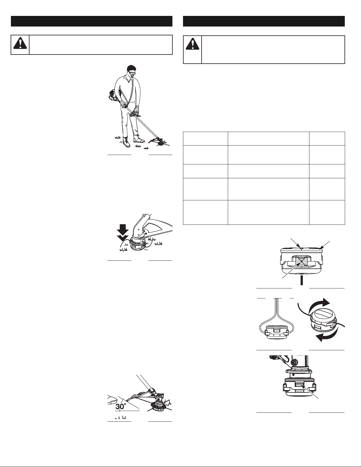
INSTRUCCIONES DE OPERACION
21
COMO SOSTENER EL RECORTADOR
Antes de operar esta unidad, párese en posición de operación (Fig. 13). Verifique
lo siguiente:
• El operador tiene protección ocular y ropa
adecuada.
• El brazo derecho está levemente doblado,
y la mano está sosteniendo el mango del
eje.
• El brazo izquierdo está recto, y la mano
está sosteniendo la manija.
• La unidad está debajo del nivel de la
cintura.
• El accesorio de corte está paralelo al suelo
y hace fácil contacto con la vegetación
que va a ser cortada sin que el operador
tenga que inclinarse.
AJUSTE DE LA LONGITUD DE LA LINEA
DE CORTE
El accesorio de corte Rapid Rewind™ le permite
soltar línea de corte sin apagar el motor. Para
soltar más línea, golpee suavemente el accesorio de corte contra el suelo (Fig. 14)
mientras opera el recortador a alta velocidad.
NOTA: Mantenga siempre la línea de corte completamente extendida. Es
más difícil soltar línea al acortarse la línea de corte.
Cada vez que se golpea la cabeza, se suelta alrededor de 25.4 mm (1 pulgada) de
línea de corte. La cuchilla en la protección del accesorio de corte detendrá la línea
en la longitud correcta si se suelta demasiada línea.
Para obtener mejores resultados, golpee la Rapid Rewind™ sobre terreno limpio o
tierra dura. Si inten ta soltar la línea sobre el césped alto, el motor podrá ahogarse.
Mantenga siempre la línea de corte completamente extendida. Es más difícil soltar
línea al acortarse la línea de corte.
NOTA: No apoye la Rapid Rewind™ sobre
el suelo mientras la unidad esté en
funcionamiento.
La línea puede cortarse por:
• Enredarse con un objeto extraño
• Fatiga normal de la línea
•
Intentar cortar hierbas gruesas y leñosas
• Forzar la línea en objetos como paredes o
postes de cercos
CONSEJOS PARA OBTENER MEJORES RESULTADOS AL RECORTAR
•
El ángulo correcto para ubicar el accesorio de corte es paralelo al suelo.
•
No fuerce el accesorio de corte. Permita que la punta de la línea realice el corte
(en especial a lo largo de paredes). Si corta con más de la punta reducirá la
eficacia del corte y puede sobrecargar el motor.
• Corte césped de más de 200 mm (8 pulgadas) trabajando de arriba hacia
abajo en pequeños incrementos para evitar el desgaste prematuro de la
línea y el arrastre del motor.
• Mueva lentamente el recortador dentro y fuera del área de corte a la altura
deseada. Realice movimientos ya sea de adelante hacia atrás y viceversa,
o de lado a lado. El corte en longitudes más cortas produce mejores
resultados.
• Recorte únicamente cuando el pasto y las hierbas estén secas.
• El cabezal de corte y el protector están diseñados de manera que la
unidad pueda cortar en cualquier dirección, de derecha a izquierda o de
izquierda a derecha.
• La vida de su línea de corte depende de:
- Seguir todas las técnicas de corte indicadas anteriormente
- El tipo de vegetación que corte
- El lugar donde se corta
Por ejemplo, la línea se desgastará más
rápido cuando corte contra un muro que
cuando corte alrededor de un árbol.
RECORTE DECORATIVO
El recorte decorativo se realiza eliminando toda
la vegetación de alrededor de los árboles,
postes, cercos, etc.
Gire toda la unidad a modo de que el accesorio de corte se ubique a un
ángulo de 30° con el suelo (Fig 15).
ADVERTENCIA:
Siempre ojo del desgaste, el oír, protección
del pie y del cuerpo para reducir el riesgo de lesión al funcionar
esta unidad.
Fig. 13
PROGRAMA DE MANTENIMIENTO
Estos procedimientos requeridos para el mantenimiento deben ser realizados con la
frecuencia indicada en la tabla. Deben ser incluidos como parte de toda puesta a
punto de cada temporada.
NOTA: Es posible que algunos procedimientos de mantenimiento
requieran herramientas o habilidades especiales. Si no está
seguro sobre estos procedimientos, lleve la unidad a Sears o a
otro proveedor de servicio calificado. Para más información, llame
al 1-800-4-MY-HOME®.
NOTA: El mantenimiento, el reemplazo o la reparación de los dispositivos y
del sistema de control de emisiones puede ser realizado por Sears o
por otra agencia de servicio calificada. Para más información, llame
al 1-800-4-MY-HOME®.
ADVERTENCIA:
Para evitar lesiones personales graves,
nunca realice manteni-miento ni reparaciones con la unidad
funcionando. Realice siempre el mantenimiento y las reparaciones
con la unidad fría. Desconecte el cable de la bujía de encendido
para cerciorarse de que la unidad no arrancará.
INSTRUCCIONES DE MANTENIMIENTO Y REPARACION
FRECUENCIA MANTENIMIENTO
REQUERIDO
CONSULTE
Antes de arrancar
el motor
Llene el tanque de combustible con
combustible nuevo
Inspeccione el aceite
Page 19
Page 20
Cada 10 horas Limpie y vuelva a aceitar el filtro de
aire
Page 23
Primer cambio a
las 10 horas
Cada 40 horas
Cambie el aceite|
Limpie el amortiguador de chispas
Page 23
Page 24
Cada 40 horas
Verifique la separación entre el brazo
oscilante y la válvula y ajuste
Verifique la condición y separación
de la bujía de encendido
Page 24
Page 25
INSTALACIÓN DE LA LÍNEA
Use sólo línea de reemplazo de
0.095 pulg. (2.41 mm). Usar otra
línea de un ancho diferente podría
ocasionar que el motor se
recaliente o falle.
NOTA: Es posible que sea
necesario quitar la línea
vieja antes de instalar la
nueva. De ser así,
consulte la sección
Remoción de la línea
vieja o de obstrucciones.
1. Alinee las flechas de la perilla
del cabezal de corte con los
ojetes de la bobina exterior,
si ya no están listos (Fig. 16)
2.
Utilizando una línea de
reemplazo de 10.5 pies (3.2 m).
Empuje un extremo de la línea a
través de uno de los ojetes
hasta que salga por el lado
opuesto. Continúe empujando
o tirando de la línea hasta que
la línea quede distribuida
uniformemente, de manera que
se vea aproximadamente 5 pies
(1.5 m) desde ambos lados del
cabezal de corte (Fig. 17)
3. Sujete la perilla del cabezal
de corte y haga girar el
cabezal de corte en el
sentido de las agujas del
reloj para enrollar la línea en
el carrete interior hasta que
salga 5 pulg. (12.7 cm) por
cada lado del cabezal de
corte (Fig. 17)
Fig. 14
Fig. 15
Fig. 17
Fig. 18
Etiquetas
Perilla
Ojete
Fig. 16
Flecha
Page 22
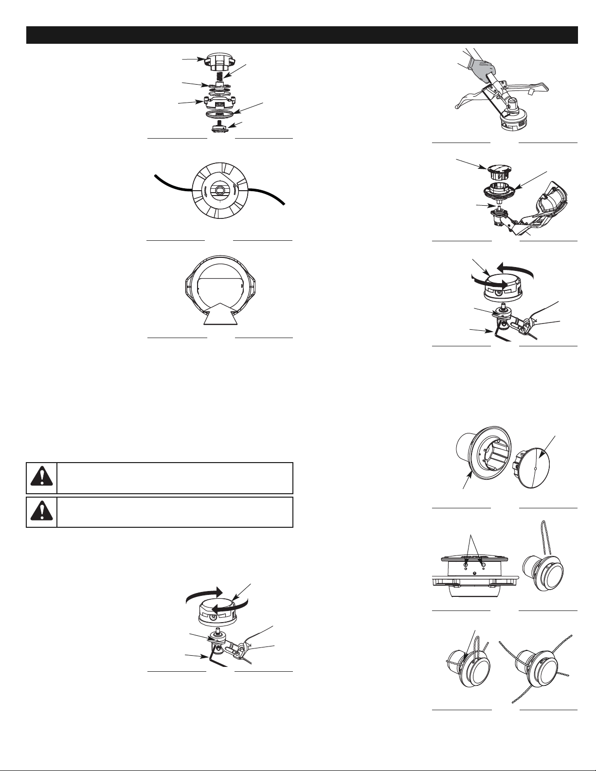
2. Alinee el orificio del buje del
eje con la ranura de la varilla
de traba e inserte la varilla de
traba en el orificio del buje del
eje (Fig. 23).
3. Sujete la varilla de traba en
su lugar sosteniéndola al
lado del brazo de la unidad
(Fig. 24).
4. Utilizando una llave de boca
de 13 mm (1/2 pulg.), apriete
firmemente el cabezal de
corte en su posición.
Para instalar la línea, vea las
instrucciones sobre reemplazo de la
línea Hassle-Free™ PLUS.
Cómo quitar el cabezal de corte
Hassle-Free™ PLUS
1. Alinee el orificio del buje del
eje con la ranura de la varilla
de traba e inserte la varilla de
traba en el orificio del buje
del eje (Fig. 22).
2. Sujete la varilla de traba en su
lugar sosteniéndola al lado
del brazo de la unidad (Fig.
23).
3. Utilizando una llave de 13 mm
(1/2 pulg.), hágala girar en
sentido de las agujas del reloj
para sacar la extensión y el
cabezal de corte del eje de
salida de la caja de
engranajes. (Fig. 24)
Cómo instalar el cabezal de
corte Rapid Rewind™
1. Alinee el orificio del buje del eje con la ranura de la varilla de traba e
inserte la varilla de traba en el orificio del buje del eje (Fig. 25).
2. Sujete la varilla de traba en su lugar sosteniéndola al lado del brazo de
la unidad (Fig. 23).
3. Atornille el accesorio de corte hacia la izquierda en el eje de salida.
Apriete firmemente. (Fig. 25)
REEMPLAZO DE LA LÍNEA
Utilice siempre la Línea en Espiral
Craftsman Hassle-Free™ XTRA
QUIET. Elija el tamaño de la línea que
mejor se ajuste al trabajo en
cuestión. La línea de color rojo está
concebida para el corte de hierba y
el desyerbe de hierbas malas
pequeñas. La línea de color negro
está concebida para el desyerbe de
hierbas malas mayores y arbustos
pequeños.
NOTA:
Antes de insertar una
nueva línea en los orificios
del cabezal de corte,
identifique claramente el
orificio adecuado. Siga las
instrucciones que aparecen
en la placa guía de la línea.
No trate de quitar el
cabezal de corte de la
unidad al cambiar la línea.
NOTA: No combine las líneas.
Use 2 negras o 2 rojas
solamente.
1. Quite la línea vieja y la placa
guía de la línea del cabezal de
corte.
2. Limpie completamente la
superficie del cabezal de
corte.
3.
Reinstale la placa guía de la
línea (Fig. 26) La placa guía es
un elemento con espiga y ajusta
de una sola forma. Si no entra
en el cabezal de corte fácilmente, NO lo fuerce. Gire la placa hasta que se
encaje fácilmente en el cabezal de corte.
22
INSTRUCCIONES DE MANTENIMIENTO Y REPARACION
NOTA: Si está bobinando la
línea utilizando una
bobina grande, haga
pasar aproximadamente
5 pies (1.5 m) de línea a
través del cabezal de
corte hacia el otro lado.
Gire el cabezal de corte
para bobinar la línea.
Cuando la línea haya
llegado a una distancia
de 5 pulgadas del
cabezal, corte la línea en
el lado de la bobina a 5
pulgadas del cabezal.
4. Arranque la unidad y golpee
el cabezal de corte contra el
suelo hasta que salga el
tramo de longitud de corte
deseada.
REMOCIÓN DE LA LÍNEA VIEJA
NOTA: Sólo deberá ser
necesario quitar la tapa
de tope si la línea se
enreda o hay alguna
obstrucción que impida
instalar la línea nueva o
que la línea avance.
1. Oprima fuertemente las
orejetas que se encuentran a
cada lado del cabezal de
corte. (Fig. 18)
NOTA: Es posible que le resulte
más fácil hacer presión en
una orejeta primero y
después la otra hacia adentro y luego hacia arriba
2. Quite la tapa de tope dejando que salte o es posible que sea necesario
mover un poco la tapa para sacarla de la bobina exterior (Fig. 19)
3. Desenrosque la línea vieja de la bobina y sáquela del orificio central de
la bobina. (Fig. 20)
4. Vuelva a colocar el carrete interior en la bobina exterior (Fig. 19).
5. Vuelva a colocar la tapa de tope alineando las lengüetas de la tapa con
los orificios de traba de lengüeta de la bobina exterior y presione
firmemente hacia abajo hasta que ambas lengüetas caigan nuevamente
en su lugar. (Fig. 21)
Para instalar una línea nueva, consulte la sección Instalación de la línea.
CÓMO CAMBIAR LOS CABEZALES DE CORTE
Esta unidad fue enviada con un cabezal de corte Hassle Free™ PLUS.
Cualquiera de los cabezales de corte puede utilizarse a discreción del
operador.
Cómo quitar el cabezal de corte Rapid Rewind™
1. Alinee el orificio del buje del
eje con la ranura de la varilla
de traba e inserte la varilla de
traba en el orificio del buje del
eje (Fig. 22).
2. Sujete la varilla de traba en
su lugar sosteniéndola al
lado del brazo de la unidad
(Fig. 23).
3. Mientras sujeta la varilla de
traba, saque el accesorio de
corte girándolo en sentido de
las agujas del reloj hasta que salga del eje de salida (Fig. 22). Guarde el
accesorio de corte para uso futuro.
Cómo instalar el cabezal de corte Hassle Free™ PLUS
1. Coloque el conjunto de cabezal de corte en el eje de salida y hágalo
girar en sentido contrario a las agujas del reloj hasta que quede
apretado con la mano. (Fig. 22)
ADVERTENCIA:
El protector accesorio de corte NO debe
estar instalado cuando use la unidad con una cuchilla. Saque el
protector accesorio de corte antes de sacar o instalar la cuchilla.
ADVERTENCIA:
Para evitar graves lesiones personales o el
daño de la unidad, no arranque ni use esta unidad con la varilla de
cierre en la ranura de la varilla de cierre.
Cabezal Rapid Rewind™
Orificio
del buje
del eje de
salida
Fig. 22
Fig. 23
Deslícese Plato
Fig. 24
Varilla de
traba
Cabezal Hassle
Free™ PLUS
Eje de
Salida
Cabezal Rapid Rewind™
Orificio
del buje
del eje de
salida
Fig. 25
Varilla de
traba
Deslícese Plato
Accesorio de corte
Fig. 26
Hoyos grandes
Fig. 27
Túnel que posiciona
Fig. 28
Fig. 20
Fig. 21
PRENSA
Fig. 19
Colocar la
tapa
Carrete
Bobina
exterior
Resorte
Gearbox
Perilla
Page 23
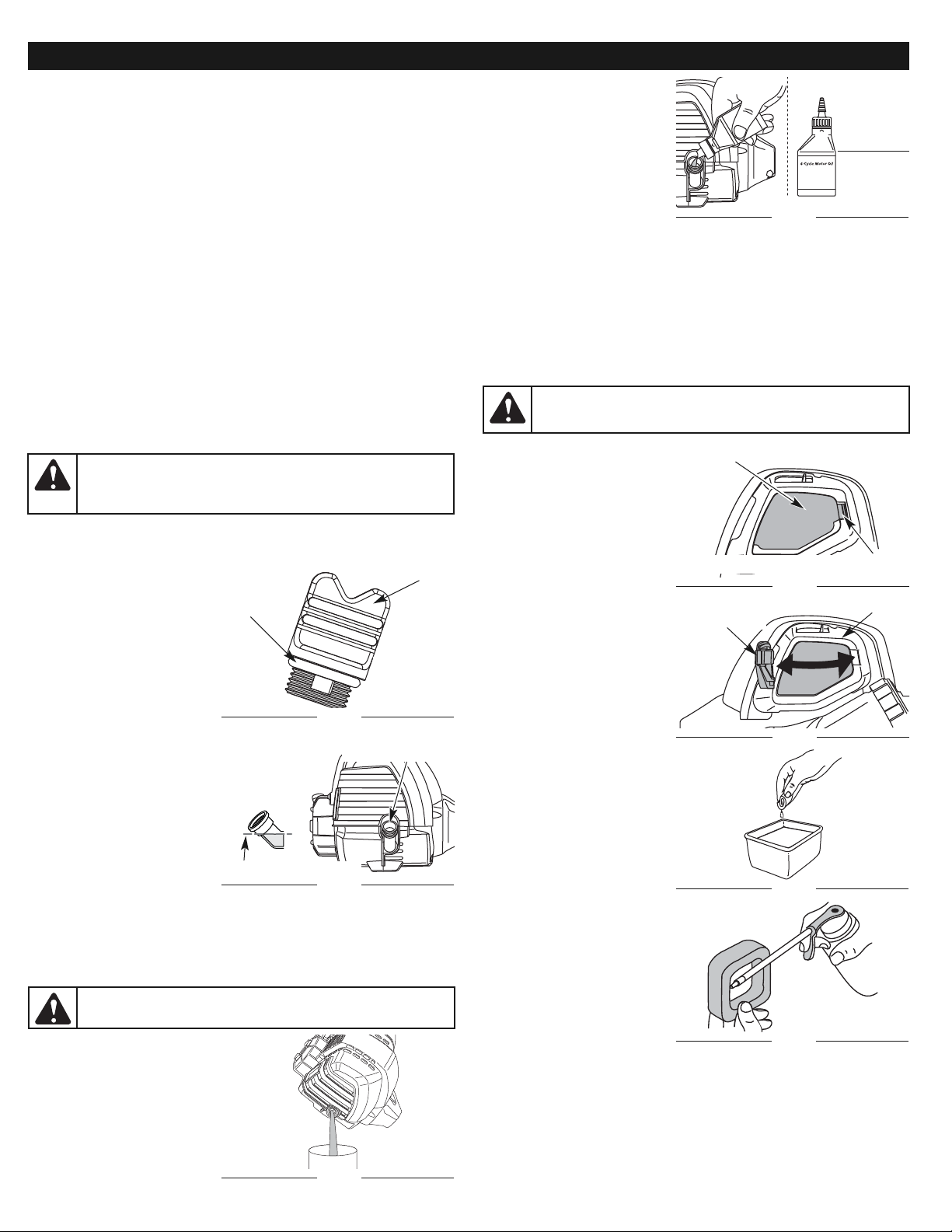
2. Vierta el aceite del orificio de
llenado de aceite en un
recipiente inclinando la
unidad hacia un lado
(Fig. 31). Deje suficiente
tiempo como para completar
el drenaje.
3.
Seque todo el aceite residual de
la unidad y limpie todo el aceite
que pueda haberse derramado.
Elimine todo el aceite de
acuerdo con las normas federales, estatales y locales.
4. Vuelva a cargar el cárter del cigüeñal con 60 ml (2.2 fl. oz.) de aceite
SAE 30 SF, SG, SH.
NOTA: Use la botella y la boquilla que guardó del uso inicial para medir la
cantidad correcta. El nivel de 60 ml (2.2 fl. oz.) está
aproximadamente en la parte superior de la etiqueta de la botella
(Fig. 32). Mida el nivel con la varilla de medición. Si el nivel está bajo,
agregue una pequeña cantidad de aceite y vuelva a medir (Fig. 30).
No lo llene demasiado.
5. Vuelva a colocar el tapón de relleno de aceite.
MANTENIMIENTO DEL FILTRO DE AIRE
Limpieza del filtro de aire
Limpie y vuelva a aceitar el filtro de
aire cada 10 horas de operación. Es
una de las partes cuyo
mantenimiento es importante. No
mantener debidamente su filtro de
aire puede resultar en
funcionamiento inadecuado o
puede causar daño permanente a
su motor.
1. Abra la cubierta del filtro de
aire presionando hacia dentro
la lengüeta de traba y sacando
la cubierta del filtro (Fig. 33 y
34).
2. Retire el filtro de aire
(Fig. 38).
3. Lave el filtro con agua y
detergente (Fig. 35).
Enjuague bien el filtro y
déjelo secar.
4. Aplique suficiente aceite
limpio de motor SAE 30 para
recubrir ligeramente el filtro
(Fig. 36).
5. Apriete el filtro para esparcir y
retirar el exceso de aceite
(Fig. 37).
6. Vuelva a colocar el filtro de
aire en la placa de base (Fig.
38).
NOTA: Si opera la unidad sin el
filtro de aire, su garantía
será ANULADA.
7. Vuelva a instalar la tapa del
filtro de aire. Coloque las dos
pequeñas lengüetas de la
cubierta del filtro de aire
sobre las dos ranuras de la
placa posterior y presione la
cubierta hacia abajo,
cerciorándose que la
lengüeta y la ranura estén
bien alineadas, hasta que
encaje en su lugar (Figuras 34 y 33).
23
INSTRUCCIONES DE MANTENIMIENTO Y REPARACION
ADVERTENCIA:
Para evitar graves lesiones personales, apague
siempre su recortador y espere que se enfríe antes de limpiarlo o
realizar todo tipo de mantenimiento.
NOTA: La placa guía de la línea debe instalarse en el cabezal de corte
antes de insertar una nueva línea.
4. Inserte ambos extremos de la línea en los orificios adecuados ubicados
al costado del cabezal de corte (Fig. 27).
5. Empuje y/o tire de la línea de modo que ésta se ajuste al cabezal central y
quede completamente extendida a través de los túneles de colocación.
(Fig. 28)
6.
Si la línea se instala correctamente, tendrá la misma longitud en ambos lados.
NOTA: Al instalar la línea nueva, asegúrese de que la línea quede lo más
uniforme posible. Cualquier variación en la longitud puede ocasionar
que la unidad vibre excesivamente. Si esto sucede, pare la unidad y
asegúrese de que la línea esté pareja.
7.
Repita los pasos del 4 al 6 para instalar la segunda línea del recortador.
NOTA: No recueste el cabezal de corte Hassle-Free™ PLUS sobre la tierra
cuando la unidad esté andando.
La línea puede romperse debido:
• A que se enrede con un objeto extraño
• A fatiga normal de la línea
• Al intento de cortar hierbas gruesas y leñosas
• A que se fuercen con objetos tales como paredes o postes de cercas
NOTA:
Durante el uso normal, la línea de corte puede desgastarse disparejamente
lo cual puede ocasionar exceso de vibraciones en la unidad. Si esto se
torna incómodo o incontrolable, pare la unidad y cambie la línea. Vea las
Instrucciones sobre Reemplazo de la Línea más arriba.
INSPECCION DEL NIVEL DE ACEITE
No podemos exagerar la importancia de verificar y mantener el nivel
correcto de aceite en el cárter del cigüeñal. Inspeccione el nivel de aceite
antes de cada uso:
1. Apague el motor y permita
que el aceite drene dentro
del cárter del cigüeñal.
2. Coloque la unidad en una
superficie plana y nivelada
para poder ver bien el nivel de
aceite.
3. Mantenga la suciedad,
recortes de césped, etc.
fuera del motor. Limpie el
área alrededor del tapón de
relleno de aceite antes de
retirarlo.
4. Retire el tapón de relleno de
aceite.
5. Compruebe el nivel de aceite.
El aceite debe quedar
exactamente en la parte
inferior de las roscas del
orificio de llenado de aceite.
(Fig. 30)
6.
Si el nivel está bajo, agregue una
pequeña cantidad de aceite en
el orificio de llenado de aceite y
vuelva a medir (Fig. 30). Repita este procedimiento hasta que el nivel de aceite
a la parte inferior de las roscas en el orificio de llenado de aceite.
NOTA: No llene demasiado la unidad.
NOTA: Verifique que el anillo en O esté en su lugar en el tapón de relleno
de aceite cuando mida y cambie el aceite (Fig. 29).
CAMBIO DEL ACEITE
En un motor nuevo, cambie el aceite
después de las 25 primeras horas de
operación. Cambie el aceite mientras
el motor aún está caliente. El aceite
fluirá con libertad y llevará más
impurezas.
1. Retire el tapón de relleno de
aceite.
ADVERTENCIA:
Para evitar un desgaste excesivo del motor y el
daño de la unidad, mantenga siempre el nivel de aceite correcto en el
cárter del cigüeñal. No opere nunca la unidad con el aceite debajo del
extremo inferior de la varilla de medición.
Anillo en
“O”
Fig. 29
Tapón de aceite
PRECAUCIÓN:
Use guantes para evitar sufrir lesiones cuando
maneje la unidad.
Cubierta del filtro de aire
Lengüeta de la tapa del filtro de aire
Cubierta del
filtro de aire
Apoye Plato
Fig. 34
Fig. 33
Fig. 31
Fig. 32
Orificio de llenado
de aceite
Fig. 30
Petróleo Llena la Línea
Agregue 41-44 ml
(1.4-1.5 fl. oz.)
Nivel de
llenado
Fig. 35
Fig. 36
Page 24
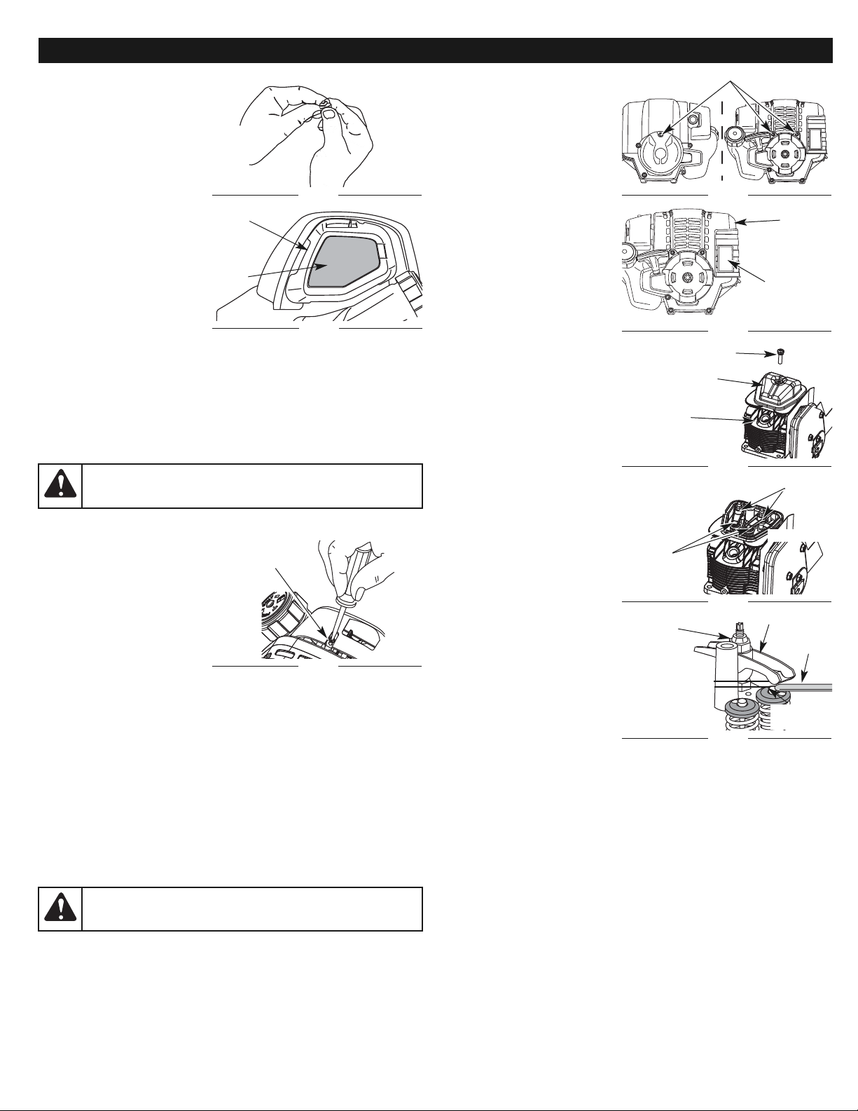
24
1.
Utilizando un destornillador de
cabeza plana o Torx T-25, quite
los dos (2) tornillos en la parte
posterior de la cubierta del
motor y el que se encuentra en
la parte delantera de la cubierta
del motor (Fig. 40).
2. Saque la cubierta del motor
(Fig. 41).
3. Desconecte el cable de la
bujía de encendido.
4.
Limpie la suciedad de alrededor
de la bujía de encendido. Saque
la bujía de encendido de la
cabeza del cilindro girando un
casquillo de 16 mm (5/8 pulg.)
en sentido antihorario.
5. Limpie la suciedad de
alrededor de la cubierta del
brazo oscilante. Saque el
tornillo que sostiene la cubierta
del brazo oscilante con un
destornillador grande de
vástago plano o con una broca
Torx T-25 (Fig. 42). Saque la
cubierta y la junta del brazo
oscilante.
6. Tire lentamente de la cuerda
de arranque para traer el
pistón hacia la parte superior
de su recorrido (conocido
como punto muerto
superior). Verifique que:
• El pistón se encuentre en la
parte superior de su recorrido
mientras mira dentro del orificio
de la bujía de encendido (Fig.
42).
• Ambos brazos oscilantes se
mueven con libertad, y
ambas válvulas están
cerradas. De no ser así,
repita este paso.
7. Deslice la galga entre el
brazo oscilante y el resorte
de retorno de la válvula.
Mida el huelgo entre el
vástago de la válvula y el
brazo oscilante (Fig. 43).
Realice esto en las válvulas
de entrada y de escape.
El huelgo recomendado para las
válvulas de entrada y de escape es
0.076 – 0.152 mm (0.003 – 0.006
pulgadas). Use un calibrador
regular de automóvil de 0.127 mm (0.005 pulgadas). El calibrador debe
deslizarse entre el balancín y el vástago de la válvula con una ligera cantidad de
resistencia, sin doblarse. Las Figuras 43 y 44 muestran la manera de medir la
holgura.
8. Si el huelgo no se encuentra dentro de las especificaciones:
a. Gire la tuerca de ajuste con una llave de 8 mm (5/16 pulgadas) o una
guía de tuercas (Fig. 44).
• Para incrementar el huelgo, gire la tuerca de ajuste en sentido
antihorario.
• Para reducir el huelgo, gire la tuerca de ajuste en sentido horario.
b. Vuelva a inspeccionar ambos huelgos, y ajuste si es necesario.
9.
Vuelva a instalar la cubierta del brazo oscilante utilizando una nueva junta.
Ajuste el tornillo a 2.2–3.4 N•m (20–30 pulgadas•libra).
10. Inspeccione la bujía de encendido y vuelva a instalar. Lea Cambio de la
Bujía de encendido.
11. Vuelva a colocar el cable de la bujía de encendido.
12. Vuelva a instalar la cubierta del motor. Verifique la alineación de la
cubierta antes de ajustar los tornillos. Ajuste los tornillos.
INSTRUCCIONES DE MANTENIMIENTO Y REPARACION
Fig. 42
Fig. 43
Fig. 44
Tornillo
Cubierta del brazo
oscilante
Bujía de
encendido
Tuercas de ajuste
Brazos
oscilantes
ENTRADA
ESCAPE
Balancín
Galga
Vástago de
la válvula
Tuerca de
ajuste
0.076–0.152 mm
(.003–.006 pulg.)
AJUSTE DEL CARBURADOR
La velocidad mínima del motor
puede ser ajustada. Puede tener
acceso al tornillo de ajuste de
mínima a través de un orificio en
la parte superior de la cubierta del
motor (Fig. 39).
NOTA: Los ajustes descuidados
pueden dañar su motor
seriamente. Los ajustes
del carburador deben ser
realizados por un
proveedor de servicio
autorizado.
Primero, Inspección del
Combustible
En general, el combustible viejo es
el motivo principal para que la
unidad no funcione en forma
adecuada. Drene y vuelva a llenar el
tanque con combustible nuevo,
limpio y sin plomo antes de hacer
ningún ajuste. Consulte la Información acerca del Aceite y Combustible.
Segundo, Limpieza del Filtro de Aire
La condición del filtro de aire es importante para el funcionamiento de la
unidad. Un filtro de aire sucio limitará el flujo de aire y cambiará la mezcla de
aire y combustible. Con frecuencia esto se confunde con un carburador
fuera de ajuste. Inspeccione la condición del filtro de aire antes de ajustar el
tornillo de velocidad mínima. Consulte la sección de Mantenimiento del
Filtro de Aire.
Tercero, Ajuste del Tornillo de Velocidad Mínima
Si después de inspeccionar el combustible y limpiar el filtro de aire el motor
aún no funciona en mínima, ajuste el tornillo de velocidad mínima según se
indica a continuación.
1. Arranque el motor y déjelo
funcionar a una mínima alta
durante un minuto para que
se caliente.
2.
Suelte el gatillo del regulador y
deje que el motor funcione en
mínima. Si el motor se para,
inserte un destornillador Phillips
pequeño en el orificio de la
cubierta del motor (Fig. 39). Gire
el tornillo de mínima hacia
adentro, en sentido horario, de a 1/8 de vuelta por vez (según sea necesario)
hasta que el motor funcione en mínima suavemente.
NOTA: El accesorio de corte no debe girar cuando el motor está
funcionando en mínima.
3. Si el accesorio de corte gira cuando el motor está funcionando en mínima,
gire el tornillo de velocidad mínima en sentido antihorario de a 1/8 de
vuelta por vez (según sea necesario) para reducir la velocidad mínima.
La inspección del combustible, la limpieza del filtro de aire y el ajuste del
tornillo de velocidad mínima debe resolver la mayoría de los problemas del
motor. Si no y cualquiera del siguiente es verdad tiene la unidad atendida a
por un Sears u otro comerciante calificado de servicio:
• El motor no funciona en mínima
• El motor fluctúa o se ahoga al acelerarlo
• Existe una pérdida de fuerza motriz
HUELGO DEL BRAZO OSCILANTE
Esto requiere el desarmado del motor. Si usted siente que no está seguro o
que no está calificado como para realizar esto, lleve la unidad a un centro de
servicio autorizado.
NOTA:
Inspeccione el huelgo de la válvula del brazo oscilante con una galga
después de las primeras 25 horas de operación y luego cada 25 horas de
operación en lo sucesivo.
•
El motor debe estar frío cuando verifique o ajuste el huelgo de la válvula.
•
Esta tarea debe ser realizada en interiores, en un área limpia y libre de polvo.
ADVERTENCIA:
Al apagar la unidad, asegúrese de que el
accesorio de corte se haya detenido antes de apoyar la unidad para
prevenir graves lesiones personales.
Fig. 40
Fig. 41
Saque los tornillos
Cubierta
del motor
Silenciador
Fig. 39
Tornillo de ajuste de
mínima
ADVERTENCIA:
Para evitar graves lesiones personales,
apague siempre su recortador y espere que se enfríe antes de
limpiarlo o realizar todo tipo de mantenimiento.
Fig. 38
Apoye
Plato
Filtro
de aire
Fig. 37
Page 25
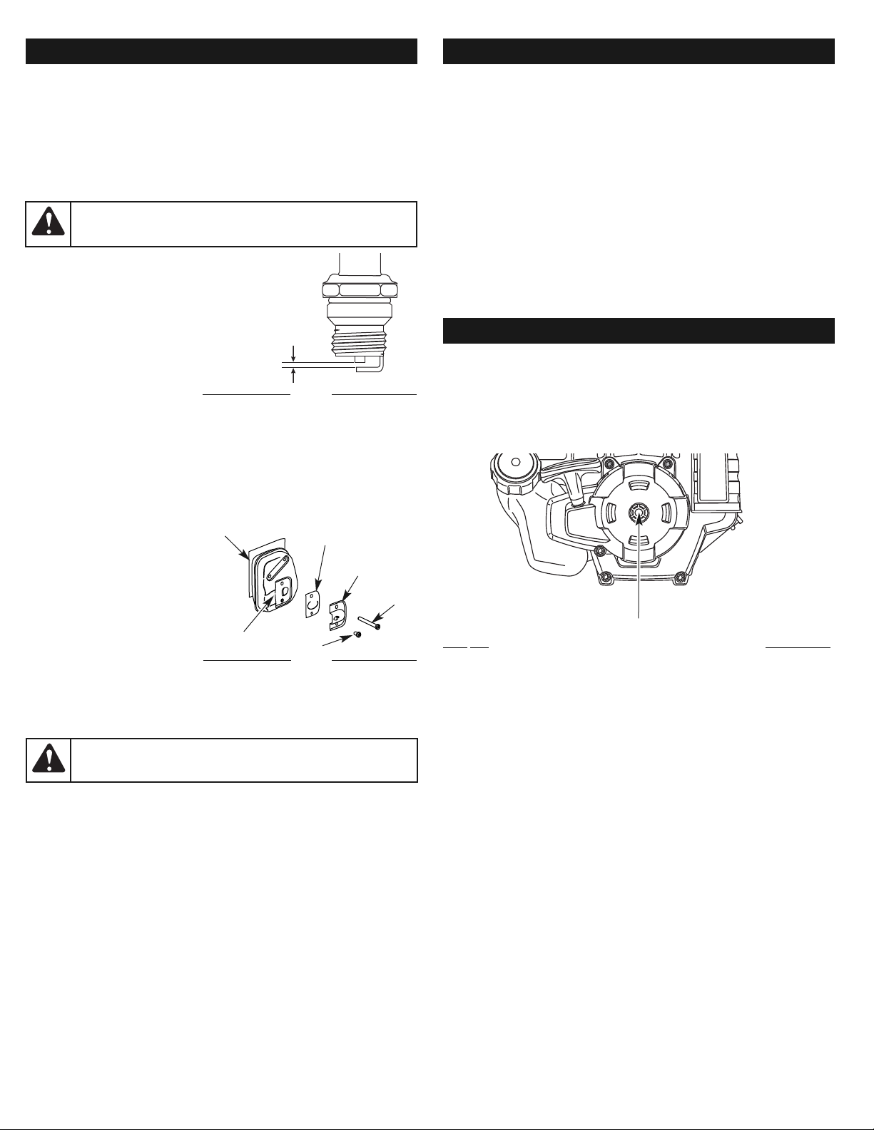
Función de Arranque Eléctrico
ACCESORIO OPCIONAL
Item No. Descripción
316.85951 ................................................Comienzo enchufable de la energía
316.85952 ..................................................Comienzo del pedacito de energía
INSTRUCCIONES DE MANTENIMIENTO Y REPARACION
3.
Deje enfriar el motor. Saque la bujía de encendido y coloque 5 gotas de
aceite de motor de buena calidad en el cilindro. Tire de la cuerda de
arranque lentamente para distribuir el aceite. Vuelva a instalar la bujía de
encendido.
NOTA: Saque la bujía de encendido y drene todo el aceite del cilindro antes
de intentar usar el recortador luego de haber estado guardado.
4. Cambie el aceite. Lea Cambio del Aceite. Elimine el aceite viejo de
acuerdo con las normas federales, estatales y locales.
5. Limpie bien la unidad y verifique que no existan partes flojas ni
dañadas. Repare o cambie las partes dañadas y ajuste los tornillos, las
tuercas o los pernos que estén flojos. La unidad está lista para ser
guardada.
TRANSPORTE
• Deje enfriar el motor antes de transportar la unidad.
• Asegure la unidad durante su transporte.
• Drene el tanque de gasolina antes de transportar la unidad.
• Ajuste la tapa de la gasolina antes de transportar la unidad.
25
CAMBIO DE LA BUJIA DE ENCENDIDO
Use una bujía de encendido Champion® RDZ4H. La separación correcta es
de 0.635 mm (0.025 pulgadas). Retire la bujía luego de cada 25 horas de
operación e inspeccione su estado.
1.
Apague el motor y espere que se enfríe. Utilizando un destornillador de cabeza
plana o Torx T-25, quite los dos (2) tornillos en la parte posterior de la cubierta
del motor y el que se encuentra en la parte delantera de la cubierta del motor
(Fig. 40).
2. Tome el alambre de la bujía con firmeza y sáquelo de la bujía de
encendido.
3.
Limpie alrededor de la bujía de
encendido. Saque la bujía de
encendido de la cabeza del
cilindro girando una llave de
casquillo de 16 mm (5/8 pulg.)
en sentido antihorario.
4.
Cambie las bujías que estén
rajadas, sucias o deterioradas.
Fije la separación de aire a
0.635 mm (0.025 pulg.)
utilizando un calibrador (Fig. 45).
5.
Instale una bujía de encendido
con la separación correcta en la cabeza del cilindro. Ajuste girando la llave de
casquillo 16 mm (5/8 pulg.) en sentido horario hasta que esté ajustada sin
huelgo.
Si usa una llave de torsión, ajuste a: 110-120 pulg.•libras (12.3-13.5 N•m)
No ajuste demasiado.
MANTENIMIENTO DEL AMORTIGUADOR DE CHISPAS
1. Saque la cubierta del amortiguador de chispas. Lea Huelgo del brazo
oscilante.
2.
Con un destornillador de cabeza
plana o un destornillador Torx de
punta T-20 y una punta T-25,
quite los tornillos que sujetan la
cubierta al silenciador (Fig. 46).
3. Tire de la lengüeta en la
cubierta hacia afuera del
silenciador y quite la
cubierta.
4. Quite la pantalla del
amortiguador de chispas de
la cubierta.
5. Limpie la pantalla del amortiguador de chispas con un cepillo de cerdas
metálicas o reemplácela.
6. Vuelva a instalar la pantalla del amortiguador de chispas, la cubierta y
el tornillo.
LIMPIEZA
Use un cepillo pequeño para limpiar la parte exterior de la unidad. No use
detergentes fuertes. Los limpiadores domésticos que contienen aceites
aromáticos como pino y limón, y con solventes como el queroseno pueden
dañar el bastidor de plástico y la manija. Seque toda la humedad con un paño
suave.
ALMACENAMIENTO
• No guarde nunca la unidad con combustible en el tanque donde los
vapores puedan llegar a una llama o chispa.
• Espere que el motor se enfríe antes de guardar la unidad.
• Guarde la unidad bajo llave para prevenir el uso por personas no
autorizadas y su daño.
• Guarde la unidad en un área seca y bien ventilada.
• Guarde la unidad fuera del alcance de los niños.
ALMACENAMIENTO POR LARGOS PERIODOS DE TIEMPO
1. Drene toda la gasolina del tanque en un recipiente. No use gasolina que
haya estado guardada durante más de 30 días. Elimine la gasolina vieja
de acuerdo con las normas federales, estatales y locales.
2. Arranque el motor y déjelo funcionar hasta que se ahogue. Esto
asegura que toda la gasolina se haya drenado del carburador.
ADVERTENCIA:
No limpie con chorro de arena, ni raspe ni
limpie los electrodos. El motor podría dañarse si penetran
pequeñas partículas en el cilindro.
0.635 mm
(0.025 in.)
Fig. 45
T-20
Tornillo
Fig. 46
T-25
Tornillo
Cobertura
Pantalla del amortiguador de
chispas
Silenciador
Ranura
CARACTERÍSTICAS ENCHUFABLES DEL COMIENZO DE LA ENERGÍA Y
DEL COMIENZO DEL PEDACITO DE ENERGÍA
Esta unidad se diseña para ser comenzada con un comienzo enchufable
opcional de la energía o el comienzo del pedacito de energía que se
vendan por separado. Si usted opta por arrancar la unidad utilizando la
función de arranque eléctrico, remítase al manual del operador del
Arranque Eléctrico para informarse sobre el procedimiento de arranque
correcto a utilizar. Si tiene preguntas, llame al 1-800-4-MY-HOME®.
ADVERTENCIA:
Para evitar graves lesiones personales, apague
siempre su recortador y espere que se enfríe antes de limpiarlo o
realizar todo tipo de mantenimiento.
INSTRUCCIONES DE MANTENIMIENTO Y REPARACION
Page 26

El accesorio de corte está atascado de hierba Pare el motor y limpie el accesorio de corte
El accesorio de corte no tiene línea Coloque una línea nueva
El carrete interior está trabado Cambie el carrete interior
La cabeza de corte está sucia Limpie el carrete interior y la bobina exterior
La línea se ha soldado Desarme, saque la sección soldada y rebobine la línea
La línea se retorció al reponerla Desarme y rebobine la línea
No hay suficiente línea expuesta
Oprima el botón de tope y tire de la línea hasta sacar 102 mm (4 pulg.) de línea
fuera del accesorio de corte.
El cabezal de corte tiene aceite Limpie el aditamento de corte
26
El tanque de combustible está vacío Llene el tanque con combustible
La bombilla de cebado no fue oprimida lo suficiente Oprima la bombilla de cebado total de 10 veces
El motor está inundado Use el procedimiento de arranque
El combustible es viejo Drene el tanque de gasolina / Agregue combustible nueva
La bujía de encendido está arruinada Cambie o limpie la bujía de encendido
Parachispas obstruido Limpie o cambie el parachispas
La temperatura exterior es por debajo de 4º C (40º F) Hale el cordón de arranque hasta un máximo de 10-15 veces
La temperatura exterior es por debajo de 32º C (90º F) Hale el cordón de arranque hasta un máximo de 10-15 veces
RESOLUCION DE PROBLEMAS
El combustible es viejo Drene el tanque de gasolina / Agregue combustible nueva
El carburador no está ajustado en forma correcta Tome a un comerciante autorizado Sears del servicio para un ajuste
El accesorio de corte está atascado de hierba Pare el motor y limpie el accesorio de corte
El filtro de aire está sucio Limpie o cambie el filtro de aire
Parachispas obstruido Limpie o cambie el parachispas
CAUSA ACCIÓN
El filtro de aire está obstruido Cambie o limpie el filtro de aire
El combustible es viejo Drene el tanque de gasolina / Agregue combustible nueva
El carburador no está ajustado en forma correcta Tome a un comerciante autorizado Sears del servicio para un ajuste
El combustible es viejo Drene el tanque de gasolina / Agregue combustible nueva
El carburador no está ajustado en forma correcta Tome a un comerciante autorizado Sears del servicio para un ajuste
El filtro de aire está sucio Limpie o cambie el filtro de aire
La bujía de encendido está arruinada Cambie o limpie la bujía de encendido
Parachispas obstruido Limpie o cambie el parachispas
EL MOTOR NO ARRANCA
EL MOTOR NO FUNCIONA EN MINIMA
EL MOTOR NO ACELERA
¿NECESITA MÁS AYUDA?
Encontrará la respuesta y mucho más en managemyhome.com – gratis!
■
Busque este y todos sus demás manuales de productos en línea.
■
Obtenga respuestas de nuestros expertos en productos para el hogar.
■
Reciba un plan de mantenimiento personalizado para su hogar.
■
Encuentre la información y las herramientas que le ayudarán en sus proyectos para su hogar.
presentado por Sears
LA CABEZA DE CORTE NO HACE AVANZAR LINEA
LA LÍNEA DE CORTE AVANZA SIN CONTROL
EL MOTOR NO TIENE SUFICIENTE POTENCIA O SE AHOGA AL CORTAR
Page 27

27
ESPECIFICACIONES
* Toda las especificaciones contenidas en este manual se basan en la información más reciente disponible en el momento de impresión del manual. Nos
reservamos el derecho de hacer cambios en cualquier momento sin aviso previo.
** Dependiente en cuál cabeza de trimmer para ser utilizado. No utilice 0.095in (2.41 Mm) línea de trimmer en el Hassle Free™ PLUS que corta cabeza.
MOTOR*
Tipo de motor. . . . . . . . . . . . . . . . . . . . . . . . . . . . . . . . . . . . . . . . . . . . . . . . . . . . . . . . . . . . . . . . . . . . . . . . . . . . . . . . . . . . . . . . . . . . . Enfriado por aire, 4 ciclos
Desplazamiento . . . . . . . . . . . . . . . . . . . . . . . . . . . . . . . . . . . . . . . . . . . . . . . . . . . . . . . . . . . . . . . . . . . . . . . . . . . . . . . . . . . . . . . . 25 cc (1.5 pulgadas cúbicas)
R.P.M. de operación . . . . . . . . . . . . . . . . . . . . . . . . . . . . . . . . . . . . . . . . . . . . . . . . . . . . . . . . . . . . . . . . . . . . . . . . . . . . . . . . . . . . . . . . . . . . 6,800 - 9,300 r.p.m.
R.P.M. de velocidad mínima . . . . . . . . . . . . . . . . . . . . . . . . . . . . . . . . . . . . . . . . . . . . . . . . . . . . . . . . . . . . . . . . . . . . . . . . . . . . . . . . . . . . . . 2,800 - 3,600 r.p.m.
Tipo de encendido . . . . . . . . . . . . . . . . . . . . . . . . . . . . . . . . . . . . . . . . . . . . . . . . . . . . . . . . . . . . . . . . . . . . . . . . . . . . . . . . . . . . . . . . . . . . . . . . . . . . Electrónico
Interruptor de encendido . . . . . . . . . . . . . . . . . . . . . . . . . . . . . . . . . . . . . . . . . . . . . . . . . . . . . . . . . . . . . . . . . . . . . . . . . . . . . . . . . . . . . . . . Interruptor oscilante
Huelgo de la válvula . . . . . . . . . . . . . . . . . . . . . . . . . . . . . . . . . . . . . . . . . . . . . . . . . . . . . . . . . . . . . . . . . . . . . . . . . . . . . . . 0.076–0.152 mm (0.003–0.006 pulg)
Separación de la bujía de encendido . . . . . . . . . . . . . . . . . . . . . . . . . . . . . . . . . . . . . . . . . . . . . . . . . . . . . . . . . . . . . . . . . . . . . . . . . . . . . 0.635 mm (0.025 pulg)
Lubricación. . . . . . . . . . . . . . . . . . . . . . . . . . . . . . . . . . . . . . . . . . . . . . . . . . . . . . . . . . . . . . . . . . . . . . . . . . . . . . . . . . . . . . . . . . . . . . . . . . . . . . . . Aceite SAE 30
Capacidad de aceite del cárter del cigüeñal . . . . . . . . . . . . . . . . . . . . . . . . . . . . . . . . . . . . . . . . . . . . . . . . . . . . . . . . . . . . . . . . . . . . . . . . . . . . 60 ml (2.2 onzas)
Combustible . . . . . . . . . . . . . . . . . . . . . . . . . . . . . . . . . . . . . . . . . . . . . . . . . . . . . . . . . . . . . . . . . . . . . . . . . . . . . . . . . . . . . . . . . . . . . . . . . . . . . . . . . . Sin plomo
Carburador . . . . . . . . . . . . . . . . . . . . . . . . . . . . . . . . . . . . . . . . . . . . . . . . . . . . . . . . . . . . . . . . . . . . . . . . . . . . . . . . . . . . . . . . . . . . . . Diafragma, multiposicional
Arranque. . . . . . . . . . . . . . . . . . . . . . . . . . . . . . . . . . . . . . . . . . . . . . . . . . . . . . . . . . . . . . . . . . . . . . . . . . . . . . . . . . . . . . . . . . . . . . . . . . . . Bobinado automático
Silenciador . . . . . . . . . . . . . . . . . . . . . . . . . . . . . . . . . . . . . . . . . . . . . . . . . . . . . . . . . . . . . . . . . . . . . . . . . . . . . . . . . . . . . . . . . . . . Amortiguado con protección
Regulador . . . . . . . . . . . . . . . . . . . . . . . . . . . . . . . . . . . . . . . . . . . . . . . . . . . . . . . . . . . . . . . . . . . . . . . . . . . . . . . . . . . . . . . . . . . . . . Retorno manual del resorte
Capacidad del tanque de combustible . . . . . . . . . . . . . . . . . . . . . . . . . . . . . . . . . . . . . . . . . . . . . . . . . . . . . . . . . . . . . . . . . . . . . . . . . . . . . . . . 12 fl.oz. (355 ml)
Bastidor del eje impulsor . . . . . . . . . . . . . . . . . . . . . . . . . . . . . . . . . . . . . . . . . . . . . . . . . . . . . . . . . . . . . . . . . . . . . . . . . . . . . . . . . . . . . . . . . . . Tubo de aluminio
Control del regulador. . . . . . . . . . . . . . . . . . . . . . . . . . . . . . . . . . . . . . . . . . . . . . . . . . . . . . . . . . . . . . . . . . . . . . . . . . . . . . . . . . . . . . . . . . . . Gatillo para el dedo
Peso de la unidad (sin combustible, con la manija, el protector y el Hassle Free®) . . . . . . . . . . . . . . . . . . . . . . . . . . . . . . . . . . . . . . . . . . . . . 7.3 kg (16 libras)
Cabezal del Recortador . . . . . . . . . . . . . . . . . . . . . . . . . . . . . . . . . . . . . . . . . . . . . . . . . . . . . . . . . . . . . . . Cabeza de Hassle Free IV™ PLUS o Rapid Rewind™
Diámetro de la bobina de línea . . . . . . . . . . . . . . . . . . . . . . . . . . . . . . . . . . . . . . . . . . . Línea Espiral Hassle Free™ XTRA QUIET o 2.41 mm (0.095 pulgadas)**
EJE IMPULSOR Y ACCESSORIO DE CORTE*
CONVENIOS DE COBERTURA DE GASTOS PARA REPARACIONES
Felicidades por haber hecho una compra inteligente. Su nuevo producto Craftsman está diseñado y fabricado para que opere de manera confiable durante
años. Pero como todos los productos, pudiera necesitar una reparación cada cierto tiempo. Por eso el tener un Convenio de Cobertura de Gastos para
Reparaciones puede ahorrarle dinero y disgustos.
Adquiera un Convenio de Cobertura de Gastos para Reparaciones ahora y protéjase de problemas y gastos inesperados.
He aquí lo que incluye el Convenio:
R Servicio proporcionado por nuestros 12,000 especialistas expertos en reparaciones profesionales
R Servicio ilimitado sin cargos por piezas ni mano de obra, en todas las reparaciones cubiertas
R Reemplazo del producto, si sus productos cubiertos no pueden arreglarse
R Descuento del 10% del precio regular del servicio y de piezas relacionadas con el servicio no cubiertas por el convenio; además,
descuento del 10% del precio regular de los chequeos de mantenimiento preventivo
R Ayuda rápida por teléfono: apoyo telefónico por parte de un técnico de Sears en los productos que requieren reparación en el hogar,
además de la programación de la reparación a una hora conveniente
Una vez que usted adquiera el Convenio, basta con una llamada telefónica para programar el servicio. Usted puede llamar a cualquier hora del día o de la
noche, o programar por Internet una cita para el servicio.
Sears tiene más de 12.000 especialistas en reparaciones profesionales, que tienen acceso a más de 4.5 millones de piezas y accesorios de calidad. Ese es el
tipo de profesionalismo con el que usted puede contar para ayudar a prolongar la vida útil de su nueva adquisición durante años. ¡Adquiera hoy mismo su
Convenio de Cobertura de Gastos para Reparaciones!
Se aplican algunas limitaciones y exclusiones. Para precios e información adicional, llame al 1-800-827-6655.
Servicio de Instalación de Sears
Para la instalación por parte de profesionales de Sears de efectos electrodomésticos; abridores de puertas de garaje, calentadores de agua y demás artículos
domésticos de mayor cuantía, en los EE.UU., llame al 1–800-4-MY-HOME
®
.
Page 28

28
NOTES
Page 29

29
NOTES
Page 30
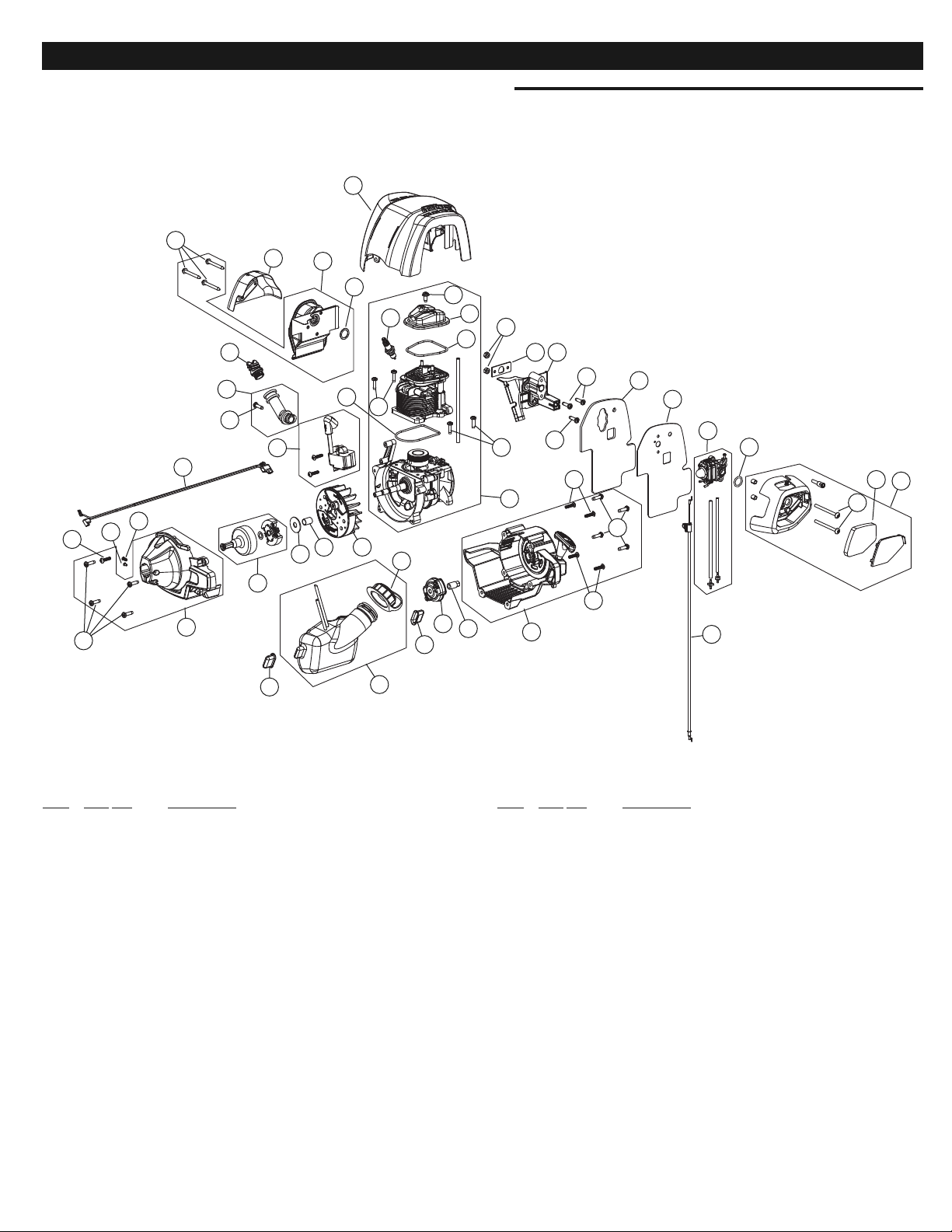
1
2
4
5
7
8
9
10
15
16
17
18
19
20
31
29
28
27
32
24
23
14
13
12
8
Item Part No. Description
1 753-06084 Aircleaner Assembly (includes 2 & 3)
2 753-06085 Air Filter
3 753-05253 Screw
4 791-181751 Carburetor O-Ring
5 753-06083 Carburetor Assembly w/ Fuel Lines
6 753-06122 Heat Shield
7 753-06082 Carburetor Baffle
8 791-181003 Screw
9 753-05904 Insulator
10 753-05673 Insulator Gasket
11 753-05248 Nut
12 753-06097 Engine Cover
13 791-181025 Screw
14 753-05901 Valve Cover
15 753-05902 Valve O-Ring
16 753-05910 Cylinder O-Ring
17 753-05784 Spark Plug
18 753-06166 Throttle Cable
19 753-06334 Muffler Assembly (includes 20 & 21)
20 753-05244 Muffler Gasket
21 753-05246 Muffler Bolt
Item Part No. Description
22 753-05907 Module Assembly
23 753-06167 Lead Wires
24 753-05400 Oil Plug Assembly
25 753-06087 Oil Fill Tube Assembly (includes 26)
26 753-05377 Cover Screw
27 753-05815 Flywheel
28 753-05814 Spacer
29 791-182396 Clutch Washer
30 753-05860 Clutch Assembly
31 753-06335 Clutch Cover Assembly (includes 26 & 40)
32 791-182519 Anti-rotation Screw
33 753-04291 Clamp Screw & Nut
34 753-06093 Fuel Tank (includes 36)
35 753-05289 Fuel Cap
36 753-05259 Fuel Tank Pad
37 753-06091 Pawl Assembly
38 753-06104 Electric Start Adapter
39 753-06096 Starter Cover Assembly (includes 26 & 40)
40 753-04595 Starter Screw
41 753-06101 Muffler Shield
42 753-06333 Short Block Assembly
(includes Crankcase, Cylinder, 8 & 13-17)
25
26
33
36
34
36
35
37
38
39
30
41
3
8
26
40
40
26
40
8
11
22
21
42
30
PARTS LIST
REPLACEMENT PARTS - MODEL 316.792021
4-CYCLE TRIMMER
6
Page 31
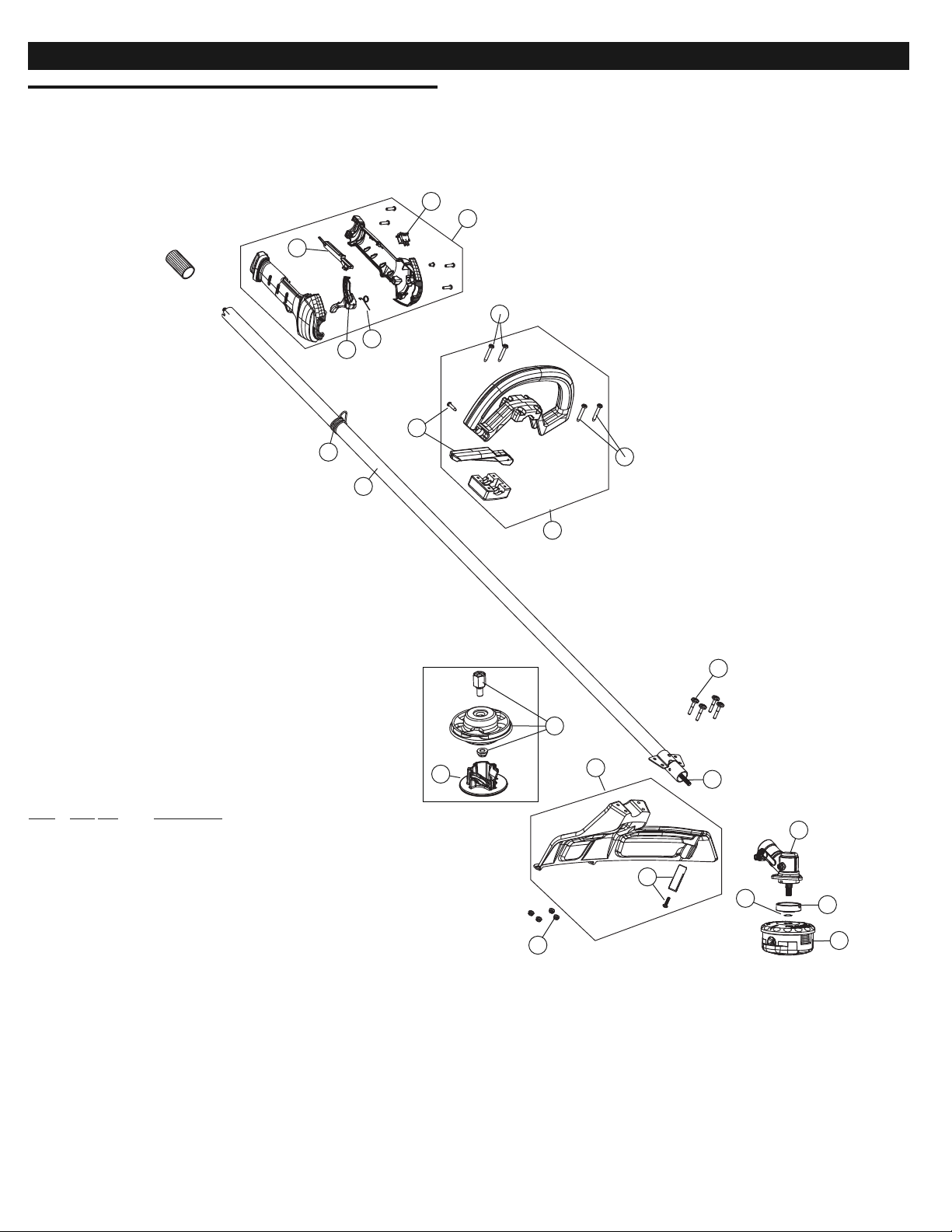
5
1
4
2
3
6
8
10
14
12
15
16
17
11
Item Part No. Description
1 753-05296 Throttle Housing Assembly (includes 2-5)
2 753-05293 Throttle Trigger
3 753-05007 Spring
4 753-05171 Throttle Lock-out
5 791-182405 Switch
6 791-610327 Shoulder Strap Clip
7 753-05474 Driver Shaft Housing
8 753-05008 D-Handle Assembly (includes 9 & 10)
9 753-05295 Barrier Bar Assembly
10 791-181070 Screw
11 753-06098 Flexible Drive Shaft
12 753-05820 Shield Assembly (includes 13)
13 753-05821 Blade Assembly
14 753-06125 Screw & Nut
15 791-182193 Gearbox
16 791-182196 Gearbox Spacer
17 753-06102 Cutting Head Assembly
18 753-04348 Palnut
19 753-05779 Fixed Line Head
20 753-05780 Glide Plate
* 753-05038 Fixed Line
* 791-613226 Locking Rod Tool
7
9
13
14
19
20
18
10
31
PARTS LIST
REPLACEMENT PARTS - MODEL 316.792021
4-CYCLE TRIMMER
Page 32

Your Home
For expert troubleshooting and home solutions advice:
www.managemyhome.com
For repair – in your home – of all major brand appliances,
lawn and garden equipment, or heating and cooling systems,
no matter who made it, no matter who sold it!
For the replacement parts, accesspries and
owner’s manuals that you need to do-it-yourself.
For Sears professional installation of home appliances
and items like garage door openers and water heaters.
1-800-4-MY-HOME
®
(1-800-469-4663)
Call anytime, day or night (U.S.A. and Canada)
www.sears.com www.sears.ca
Our Home
For repair of carry-in items like vacuums, lawn equipment,
and electronics, call anytime for the location of your nearest
Sears Parts & Repair Service Center
1-800-488-1222 (U.S.A.) 1-800-469-4663 (Canada)
www.sears.com www.sears.ca
To purchase a protection agreement on a product serviced by Sears:
1-800-827-6655 (U.S.A.) 1-800-361-6665 (Canada)
Para pedir servicio de reparación
a domicilio, y para ordenar piezas:
1-800-SU-HOGAR
®
(1-888-784-6427)
Au Canada pour service en français:
1-800-LE-FOYER
MC
(1-800-533-6937)
www.sears.ca
® Registered Trademark / ™ Trademark / SMService Mark of Sears Brands, LLC
® Marca Registrada / ™ Marca de Fábrica / SMMarca de Servicio de Sears Brands, LLC
MC
Marque de commerce / MDMarque déposée de Sears Brands, LLC © Sears Brands, LLC
Get it fixed, at your home or ours!
 Loading...