

Craftsman 316791990 Owner’s Manual

Operator's Manual
4-Cycle
WEEDWACKER ®GAS TRIMMER
Model No. 316.791990
• SAFETY
• ASSEMBLY
• OPERATION
• MAINTENANCE
• PARTS LIST
• ESPANOL, E 15
CAUTION: Before using this
product, read this manual and
follow all safety rules and
operating instructions.
Sears, Roebuck and Co., Hoffman Estates, IL 60179, U.S.A.
Visit our website" www.sears.com/craftsman
P/N 769-03874 2/08
CALIFORNIA PROPOSITION 65 WARNING
THE ENGINE EXHAUST FROM THIS PRODUCT CONTAINS
CHEMICALS KNOWN TO THE STATE OF CALIFORNIA TO CAUSE
CANCER, BIRTH DEFECTS OR OTHER REPRODUCTIVE HARM.
The purpose of safety symbols is to attract your attention to possible
dangers. The safety symbols, and their explanations, deserve your
careful attention and understanding. The safety warnings do not by
themselves eliminate any danger. The instructions or warnings they
give are not substitutes for proper accident prevention measures.
SYMBOL MEANING
TABLE OF CONTENTS
Safety Rules .......................................... 2
Warranty ............................................. 4
Know Your Unit ........................................ 4
Assembly Instructions ................................... 4
Oil and Fuel Information ................................. 5
Starting/Stopping Instructions ............................ 6
Operating Instructions ................................... 6
Maintenance and Repair Instructions ....................... 7
Cleaning and Storage .................................. 10
Troubleshooting Chart .................................. 10
Specifications ........................................ 11
Parts List ............................................ 30
Service Numbers .............................. Back Cover
SPARK ARRESTOR NOTE
NOTE: For users on U.S. Forest Land and in the states of California,
Maine, Oregon and Washington. All U.S. Forest Land and the state of
California (Public Resources Codes 4442 and 4443), Oregon and
Washington require, by law that certain internal combustion engines
operated on forest brush and/or grass-covered areas be equipped with a
spark arrestor, maintained in effective working order, or the engine be
constructed, equipped and maintained for the prevention of fire. Check
with your state or local authorities for regulations pertaining to these
requirements. Failure to follow these requirements could subject you to
liability or a fine. This unit is factory equipped with a spark arrestor. If
it requires replacement, ask your LOCAL SERVICE DEALER to install the
Accessory Part #753-05810 Spark Arrestor Kit.
All information, illustrations, and specifications in this manual are based
on the latest product information available at the time of printing. We
reserve the right to make changes at any time without notice.
= IMPORTANT SAFETY INSTRUCTIONS =
_, AFETY ALERT: Indicates danger, warning or caution.
Attention is required in order to avoid serious personal
injury. May be used in conjunction with other symbols or
pictographs.
NOTE: Advises you of information or instructions vital to the
operation or maintenance of the equipment.
serious injury to yourself or to others. Always follow the
safety precautions to reduce the risk of fire, electric shock
DANGER: Failure to obey a safety warning will result in
and personal injury.
WARNING: Failureto obey a safetywarning can resultininjury to yourself and others. Always follow the safety precautions
to reduce the risk of fire,electric shock and personal injury.
CAUTION: Failure to obey a safety warning may result inproperty damage or personal injury to yourself or to others.
Always follow the safety precautions to reduce the risk of fire
electric shock and personal injury.
Read the Operator's Manual and follow all warnings and safety
instructions.Failureto do so can result in serious injury to the operator
and/or bystanders. FOR QUESTIONS, CALL 1-800-659-5917
READ ALL INSTRUCTIONS BEFORE OPERATING
• Read the instructions carefully. Be familiar with the controls and
proper use of the unit.
• Do not operate this unit when tired, ill, or under the influence of
alcohol, drugs, or medication.
• Children and teens under the age of 15 must not use the unit,
except for teens guided by an adult.
• All guards and safety attachments must be installed properly
before operating the unit.
• Inspect the unit before use. Replace damaged parts. Check for fuel
leaks. Make sure allfasteners are in place and secure. Replace parts
that are cracked, chipped, or damaged in any way. Do not operate the
unit with loose or damaged parts.
• Carefully inspect the area before starting the unit. Remove all
debris and hard or sharp objects such as glass, wire, etc.
• Be aware of the risk of injury to the head, hands and feet.
• Clear the area of children, bystanders, and pets. At a minimum, keep all
children, bystanders, and pets outside a 50 feet (15 m.) radius; there
still may be a risk to bystanders from thrown objects. Bystanders
should be encouraged to wear eye protection. Ifyou are approached,
stop the unit immediately.
• Use only Craftsman Hassle-Free TM XTRA QUIET Spiral
Lineoriginal equipment manufacturer replacement line. Never use
metal-reinforced line, wire or rope. These can break off and become
dangerous projectiles.
• Squeeze the throttle control and check that it returns automatically to
the idle position. Make all adjustments or repairs before using unit.
SAFETY WARNINGS FOR GAS UNITS
_L_ ARNING: Gasoline is highly flammable and its vapors I
• Store fuel only in containers specifically designed and approved
• Avoid creating a source of ignition for spilled fuel. Do not start the
• Always stop the engine and allow it to cool before filling the fuel tank.
• Add fuel in a clean, well-ventilated outdoor area where there are no
• Move the unit at least 30 feet (9.1m)from the fueling source and site
WHILE OPERATING
• Never start or run the unit inside a closed room or building. Breathing
• Wear safety glasses or goggles that aremarked as meeting ANSI
can explode if ignited. Take the following precautions:
for the storage of such materials.
engine until fuel vapors dissipate.
Never remove the cap of the fuel tank, or add fuel, when the engine
is hot. Never operate the unit without the fuel cap securely in place.
Loosen the fuel tank cap slowly to relieve any pressure in the tank.
sparks or flames. Slowly remove the fuel cap only after stopping engine.
Do not smoke while fueling. Wipe up any spilled fuel from the unit
immediately.Always wipe unit dry before using.
before starting the engine. Do not smoke orallow sparks and open
flames near the area while adding fuel or operating the unit.
exhaust fumes can kill. Operate this unit only in a well ventilated
outdoor area.
Z87.1-1989 standards. Also wear ear/hearing protection when
operating this unit. Wear a face or dust mask if the operation isdusty.
Long sleeve shirts are recommended.
J
• Wear heavy, long pants, boots and gloves. Do not wear loose
clothing, jewelry, short pants, sandals or go barefoot. Secure hair
above shoulder level.
• The cutting attachment shield must always be in place while
operating the unit. Do not operate unit without both trimming lines
extended, and the proper line installed. Do not extend the
trimming line beyond the length of the shield.
• This unit has a clutch. The cutting attachment remains stationary
when the engine is idling. If it does not, have the unit adjusted by
an authorized service technician.
• Adjust the D-handle to your size to provide the best grip.
• Be sure the cutting attachment is not in contact with anything
before starting the unit.
• Use the unit only in daylight or good artificial light.
• Avoid accidental starting. Be in the starting position whenever
pulling the starter rope. The operator and unit must be in a stable
position while starting. See Starting/Stopping Instructions.
• Use the right tool. Only use this tool for the purpose intended.
• Do not overreach. Always keep proper footing and balance.
• Always hold the unit with both hands when operating. Keep a firm
grip on both the front and rear handle or grips.
• Keep hands, face, and feet at a distance from all moving parts. Do
not touch or try to stop the cutting attachment when it is rotating.
• Do not touch the engine or muffler. These parts get extremely hot from
operation. They remain hot for a short time after you turn off the unit.
• Do not operate the engine faster than the speed needed to cut, trim or
edge. Do not run the engine at high speed when you are not cutting.
• Always stop the engine when cutting is delayed or when walking
from one cutting location to another.
• if you strike or become entangled with a foreign object, stop the engine
immediately and check for damage. Do not operate before repairing
damage. Do not operate the unit with loose or damaged parts.
• Stop and switch the engine to off for maintenance, repair, or for
changing the cutting attachment or other attachments.
• Use only original equipment manufacturer replacement parts and
accessories for this unit. These are available from your authorized
service dealer. Use of any unauthorized parts or accessories
could lead to serious injury to the user, or damage to the unit, and
void your warranty.
• Keep unit clean of vegetation and other materials. They may
become lodged between the cutting attachment and shield.
• To reduce fire hazard, replace faulty muffler and spark arrestor,
keep the engine and muffler free from grass, leaves, excessive
grease or carbon build up.
OTHER SAFETY WARNINGS
• Never store the unit, with fuel in the tank, inside a building where
fumes may reach an open flame or spark.
• Allow the engine to cool before storing or transporting. Be sure to
secure the unit while transporting.
• Store the unit in a dry area, locked up or up high to prevent
unauthorized use or damage, out of the reach of children.
• Never douse or squirt the unit with water or any other liquid. Keep
handles dry, clean and free from debris. Clean after each use. See
the Cleaning and Storage instructions.
• Keep these instructions. Referto them often and usethem to instruct other
users.Ifyou loan someone this unit, also loan them these instructions.
SAVE THESE INSTRUCTIONS
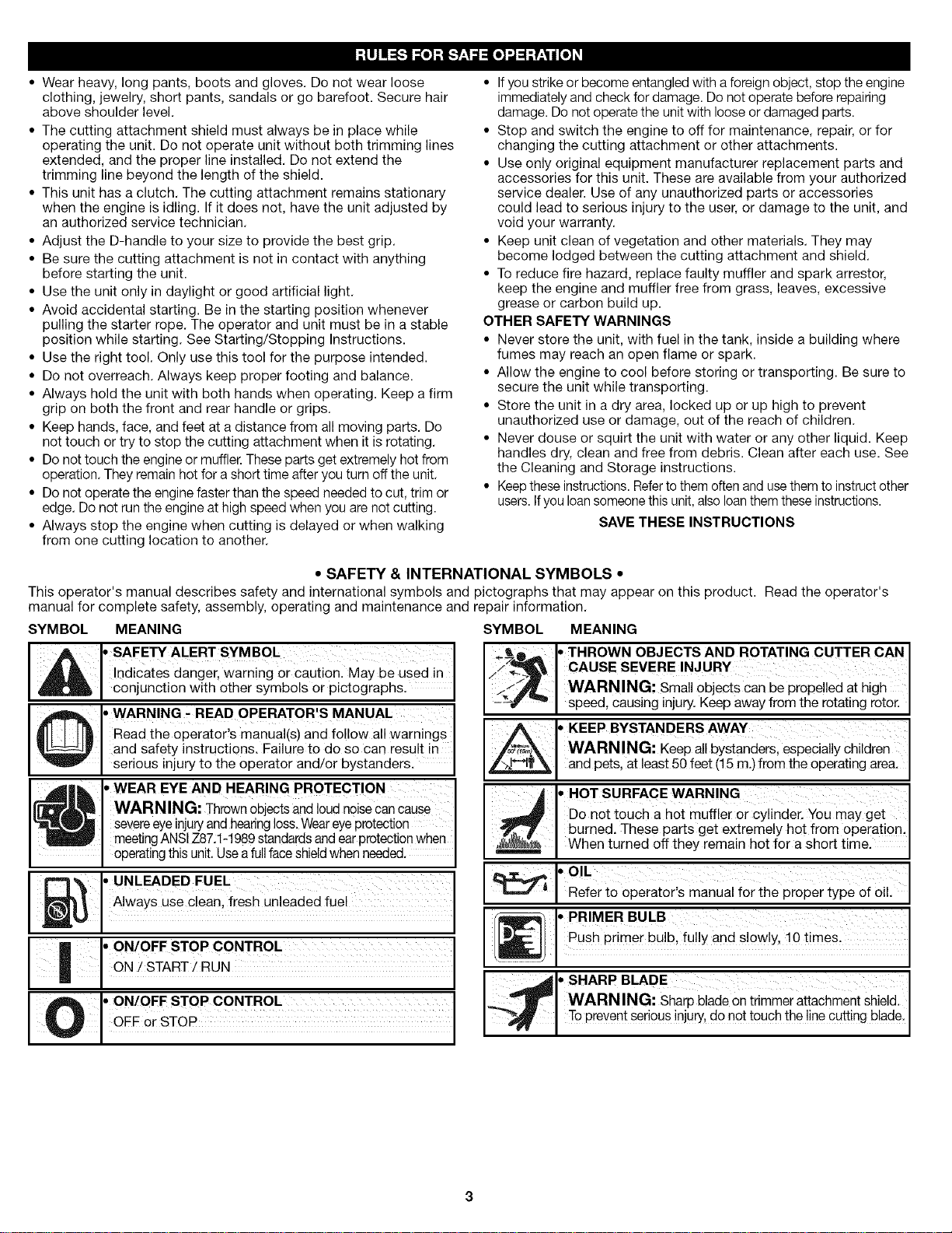
• SAFETY & INTERNATIONAL SYMBOLS •
This operator's manual describes safety and international symbols and pictographs that may appear on this product. Read the operator's
manual for complete safety, assembly, operating and maintenance and repair information.
SYMBOL MEANING SYMBOL MEANING
,,THROWN OBJECTS AND ROTATING CUTTER CAN
indicates danger, warning or caution. May be used in
* SAFETY ALERT SYMBOL
J. conjunct on wth other symbo s or p ctographs.
Read the operator's manual(s) and follow all warnings
lO • WARNING - READ OPERATOR'S MANUAL
and safety instructions. Failure to do so can result in
[ serous njury to the operator and/or bystanders.
• WEAR EYE AND HEARING PROTECTION
WARNING: Thrownobjects and loud noise cancause
severeeyeinjuryand hearingloss.Weareye protection
meetingANSIZ87.1-1989standardsandearprotection when
operatingthis unit. Use a fullfaceshieldwhen needed.
• UNLEADED FUEL
Always use clean, fresh unleaded fuel
io ON/OFF STOP CONTROL
J ON / START! RUN
/i iI
CAUSE SEVERE INJURY
WARNING: small objects can be propelled at high
speed, causing injury. Keep away from the rotating rotor.
, KEEP BYSTANDERS AWAY
WARNING: Keep all bystanders, especially children
and pets, at least 50 feet (15 m.) from the operating area.
• HOT SURFACE WARNING
DonottouchahotmufflerorCylinder,Youmayget
burned. These parts get extremely hot from operation.
When turned off they remain hot for a short time.
.OIL
Refer to operator's manual for the proper type of oil.
' PRIMER BULB
Push primer bulb, ful!y and slowly, !0 time&
• SHARP BLADE
WARNING: sharP blade on trimmer attachment shield.
To prevent serious injury,donor touch the line cutting blade.
CRAFTSMAN PROFESSIONAL FULL WARRANTY
If this Craftsman Professional product fails due to a defect in material or workmanship within three years from the date of purchase, return it
to any Sears store, Parts and Repair Service Center, or other Craftsman outlet in the United States for free repair (or replacement if repair
proves impossible).
This warranty applies for only one year if this product is ever used for commercial or rental purposes.
This warranty covers ONLY defects in material and workmanship. Sears will NOT pay for:
• Expendable items which can wear out from normal use within the warranty period, such as cutting line, air cleaner or spark plug.
• Repairs necessary because of accident or failure to operate or maintain the product according to all supplied instructions.
• Preventive maintenance, product tune-ups, or carburetor cleanings or adjustments.
This warranty gives you specific legal rights, and you may also have other rights which vary from state to state.
Sears, Roebuck and Co., Hoffman Estates, IL 60179
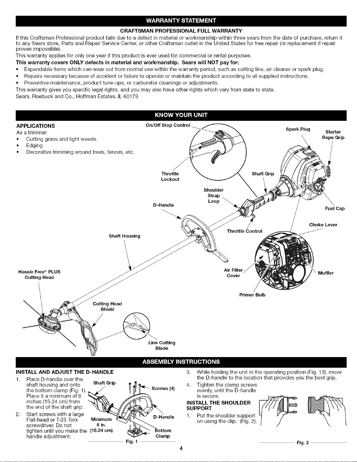
APPLICATIONS
As a trimmer:
• Cutting grass and light weeds.
• Edging
• Decorative trimming around trees, fences, etc.
Shaft Housing
Hassle Free ®PLUS
Cutting Head
Cutting Head
Shield
On/Oft Stop
Throttle
Lockout
D-Handle
Shoulder
Strap
Loop
Throttle Control
Air Filter
Cover
Primer Bulb
Shaft Grip
Spark Plug
Starter
Rope Grip
Fuel Cap
Choke Lever
INSTALL AND ADJUST THE D-HANDLE
1 Place D-handle over the
shaft housing and onto Shaft Grip
the bottom clamp (Fig. 1).
Place it a minimum of 6
inches (15.24 cm) from --
the end of the shaft grip.
2. Start screws with a large
Flat-head or T-25 Torx Minimum
screwdriver. Do not 6 in.
tighten until you make the (15.24 cm)
handle adjustment.
Fig. 1
Line Cutting
Blade
D-Handle
Clamp
(4)
3.
While holding the unit in the operating position (Fig. 13), move
the D-handle to the location that provides you the best grip.
4.
Tighten the clamp screws
evenly, until the D-handle
is secure.
INSTALL THE SHOULDER
SUPPORT
1. Put the shoulder support
on using the clip. (Fig. 2).
Fig. 2
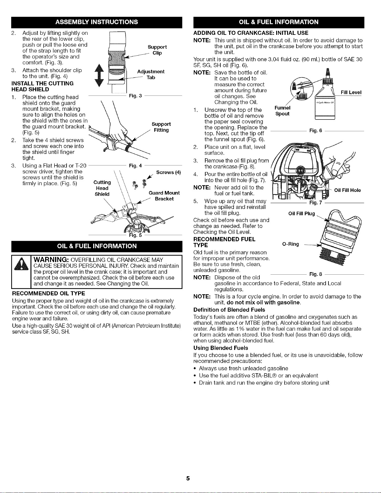
2. Adjust by lifting slightly on
the rear of the lower clip,
push or pull the loose end
of the strap length to fit
the operator's size and
comfort. (Fig. 3).
,&
3. Attach the shoulder clip
to the unit. (Fig. 4)
INSTALL THE CUTTING
HEAD SHIELD
1. Place the cutting head Fig. 3
shield onto the guard \ \
mount bracket, making \ \
sure to align the holes on \ \
the shield with the ones in _ \
the guard mount bracket. K.. / _ Support
(Fig. 5) _----------_\\ \"_I_ ._ Fitting
2. Take the 4 shield screws _x.x__l_'_x_" _
and screw each one into _ \_. _h_..._
the shield until finger
tight.
3. Using a Flat Head or T-20 Fig. 4
screws until the shield is _/
firmly in place. (Fig. 5)
screw driver, tighten the ¢_2_g _ _ _ Screws (4)
Shield \ \ GuardMount
Fig. 5
CAUSE SERIOUS PERSONAL INJURY. Check and maintain
the proper oil level in the crank case; it is important and
'_i WARNING; OVERFILLING OIL CRANKCASE MAY
cannot be overemphasized. Check the oil before each use
and change it as needed. See Changing the Oil.
RECOMMENDED OIL TYPE
Using the proper type and weight of oil in the crankcase is extremely
important. Check the oil before each use and change the oil regularly.
Failure to use the correct oil, or using dirty oil, can cause premature
engine wear and failure.
Use a high-quality SAE 30 weight oil of API (American Petroleum Institute)
service class SE SG, SH.
ADDING OIL TO CRANKCASE: INITIAL USE
NOTE: This unit is shipped without oil. In order to avoid damage to
the unit, put oil in the crankcase before you attempt to start
the unit.
Your unit is supplied with one 3.04 fluid oz. (90 ml.) bottle of SAE 30
SE SG, SH oil (Fig. 6).
NOTE: Save the bottle of oil.
It can be used to
measure the correct
amount during future
Fill Level
oil changes. See
Changing the Oil.
1. Unscrew the top of the
bottle of oil and remove
Funnel
Spout
the paper seal covering
the opening. Replace the
top. Next, cut the tip off
Fig. 6
the funnel spout (Fig. 6).
2. Place unit on a flat, level
surface.
3. Remove the oil fill plug from
the crankcase (Fig. 8).
4. Pour the entire bottle of oil
into the oil fill hole (Fig. 7).
NOTE: Never add oil to the
fuel or fuel tank.
5. Wipe up any oil that may
have spilled and reinstall
Fig. 7
Oil Fill Hole
the oil fill plug.
Check oil before each use and
change as needed. Refer to
Checking the Oil Level.
RECOMMENDED FUEL
TYPE
Old fuel is the primary reason
O-Ring
Oil Fill
for improper unit performance.
Be sure to use fresh, clean,
unleaded gasoline.
NOTE: Dispose of the old
Fig. 8
gasoline in accordance to Federal, State and Local
regulations.
NOTE: This is a four cycle engine. In order to avoid damage to the
unit, do not mix oil with gasoline.
Definition of Blended Fuels
Today's fuels are often a blend of gasoline and oxygenates such as
ethanol, methanol or MTBE (ether). Alcohol-blended fuel absorbs
water. As little as 1% water in the fuel can make fuel and oil separate
or form acids when stored. Use fresh fuel (less than 60 days old),
when using alcohol-blended fuel.
Using Blended Fuels
Ifyou choose to use a blended fuel, or its use is unavoidable, follow
recommended precautions:
• Always use fresh unleaded gasoline
• Use the fuel additive STA-BIL® or an equivalent
• Drain tank and run the engine dry before storing unit
5
UsingFuelAdditives
WARN ING: Gasoline is extremely flammable. Ignited
,_ vapors may explode. Always stop the engine and allow it
The use of fuel additives, such as STA-BIL® Gas Stabilizer or an
equivalent, will inhibit corrosion and minimize the formation of gum
deposits. Using a fuel additive can keep fuel from forming harmful
deposits in the carburetor for up to six (6) months. Add 0.8 oz. (23 ml.) of
fuel additive per gallon of fuel according to the instructions on the fuel
additive container. NEVER add fuel additives directly to the unit's gas tank.
FUELING THE UNIT
I_, ARNING: Remove fuel cap slowly to avoid injury from
1. Remove the fuel cap (Fig. 9).
2. Place the gas container's spout into the fill hole on the fuel tank
NOTE: Do not overfill the
3. Wipe up any gasoline that
4. Reinstall the fuel cap.
5. Move the unit at least 30
STARTING INSTRUCTIONS
to cool before filling the fuel tank. Do not smoke while
filling the tank. Keep sparks and open flames at a distance
from the area.
WARNING: Add fuel in a clean, well ventilated outdoor
area. Wipe up any spilled fuel immediately. Avoid creating
a source of ignition for spilt fuel. Do not start the engine
until fuel vapors dissipate.
fuel spray. Never operate the unit without the fuel cap
securely in place.
(Fig. 9) and fill the tank. Gas Can Spout
tank.
may have spilled.
ft. (9.1 m) from the fueling
source and site before
starting the engine. Fuel Cap
./,
Fig. g
WARNING: Operate this unit only in a well-ventilatedoutdoor area. Carbon monoxide exhaust fumes can be
lethal in a confined area.
WARN ING: Avoid accidental starting. Make sure you are
in the starting position when pulling the starter rope (Fig. 12).
To avoid serious injury, the operator and unit must be
in a stable position while starting.
1. Check the oil level in stop/off
the crankcase. Refer
to Checking the Oil Start/On
Level.
2. Fill the fuel tank with
fresh, clean unleaded i
gasoline. Refer to
Fueling the Unit.
NOTE: There is no need
to turn the unit
on. The On/Off
Stop Control is in
the ON ( I ) position at all times (Fig. 10).
throttle Control
Fig. 10
Fuel Tank
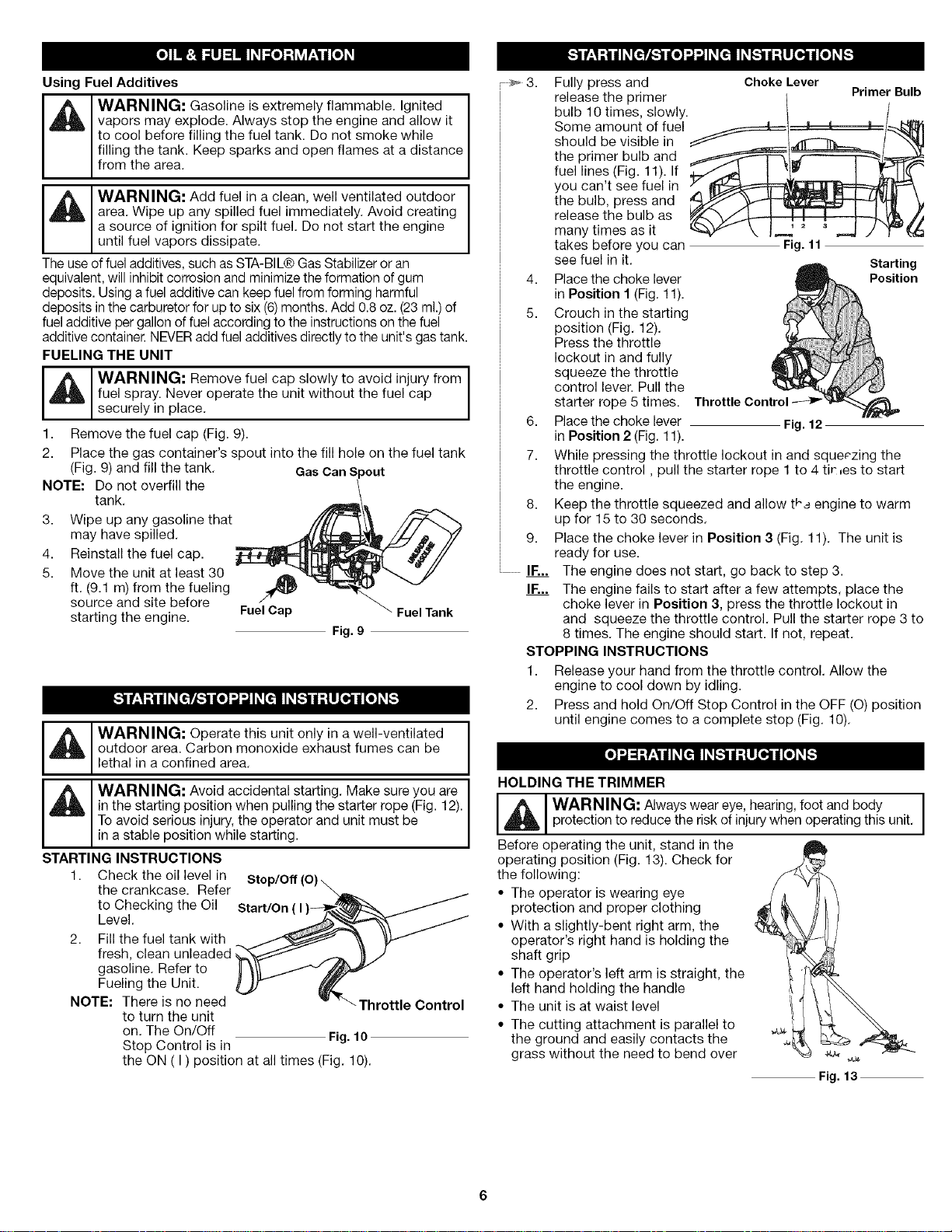
3.
Fully press and
release the primer
bulb 10 times, slowly.
Some amount of fuel
should be visible in
the primer bulb and
fuel lines (Fig. 11). If
you can't see fuel in
the bulb, press and
release the bulb as
many times as it
takes before you can
see fuel in it. _ Starting
4. Place the choke lever _ Position
in Position 1 (Fig. 11).
5. Crouch in the starting
position (Fig. 12).
Press the throttle
lockout in and fully
squeeze the throttle
control lever. Pull the
starter rope 5 times. Throttle Con
6. Place the choke lever Fig. 12
in Position 2 (Fig. 11).
7. While pressing the throttle lockout in and squeezing the
throttle control, pull the starter rope 1 to 4 tir:_es to start
the engine.
8,
Keep the throttle squeezed and allow t,a engine to warm
up for 15 to 30 seconds.
9.
Place the choke lever in Position 3 (Fig. 11). The unit is
ready for use.
IF...
The engine does not start, go back to step 3.
IF...
The engine fails to start after a few attempts, place the
choke lever in Position 3, press the throttle lockout in
and squeeze the throttle control. Pull the starter rope 3 to
8 times. The engine should start. If not, repeat.
STOPPING INSTRUCTIONS
1. Release your hand from the throttle control. Allow the
engine to cool down by idling.
2. Press and hold On/Off Stop Control in the OFF (O) position
until engine comes to a complete stop (Fig. 10).
HOLDING THE TRIMMER
'_1 WARNING: Always wear eye, hearing, foot and body
Before operating the unit, stand in the
operating position (Fig. 13). Check for
the following:
• The operator is wearing eye
• With a slightly-bent right arm, the
• The operator's left arm is straight, the
• The unit is at waist level
• The cutting attachment is parallel to
protection to reduce the risk of injury when operating this unit.
protection and proper clothing
operator's right hand is holding the
shaft grip
left hand holding the handle
the ground and easily contacts the
grass without the need to bend over
Choke Lever
Fig. 11
Primer Bulb
Fig. 13
TIPSFORBESTTRIMMINGRESULTS
• For best trimming results, operate unit at full throttle.
• Keep the cutting attachment parallel to the ground.
• Do not force the cutting attachment. Allow the tip of the line to do
the cutting, especially along walls. Cutting with more than the tip
will reduce cutting efficiency and may overload the engine.
• Cut grass over 8 inches (200 mm) by working from top to bottom
in small increments to avoid premature line wear or engine drag.
• Slowly move the trimmer into and out of the cutting area at the
desired height. Move either in a forward-backward or side-to-side
motion. Cutting shorter lengths produces the best results.
• Trim only when grass and weeds are dry.
• The life of your cutting line is dependent upon:
• Proper adherence of explained trimming techniques
• What vegetation is cut
• Where vegetation is cut
For example, the line will wear faster
when trimming against a foundation wall
as opposed to trimming around a tree.
DECORATIVE TRIMMING
Decorative trimming is accomplished by
removing all vegetation around trees,
posts, fences and more.
Rotate the whole unit so that the cutting . L_,_
attachment is at a 30° angle to the Fig. 14
ground (Fig. 14).
MAINTENANCE SCHEDULE
_1_ I WARNING: To prevent serious injury, never perform
Perform these required maintenance procedures at the frequency
stated in the table. These procedures should also be a part of any
seasonal tune-up.
NOTE: Some maintenance procedures may require special tools or
NOTE: Maintenance, replacement, or repair of the emission
engine Check oil p. 6
maintenance or repairs with unit running. Always service
and repair a cool unit.
skills. If you are unsure about these procedures take your unit to
Sears or other qualified service dealer. Call 1-800-4-MY-HOME ®
for more information.
control devices and system may be performed by a Sears
or other qualified service dealer. Call 1-800-4-MY-HOME ®
for more information.
FREQUENCY MAINTENANCE REQUIRED SEE
Before starting Fill fuel tank with fresh fuel p. 4
Every 10 hours Clean and oil air filter p. 5
Every 25 hours Change oil p. 5
Change oil p. 5
Clean spark arrestor and change oil p. 6
Every 25 hours Check rocker arm to valve clearance p. 6
and adjust
Check rocker arm to valve clearance p. 6
and adjust
Check spark plug condition and gap p. 6
LINE REPLACEMENT
Always use Craftsman Hassle-Free TMXTRA QUIET Spiral Line.
Choose the line size best suited for the job at hand. Red colored line
is designed for cutting grass and small weeds. Black colored line is
designed for cutting larger weeds and light brush.
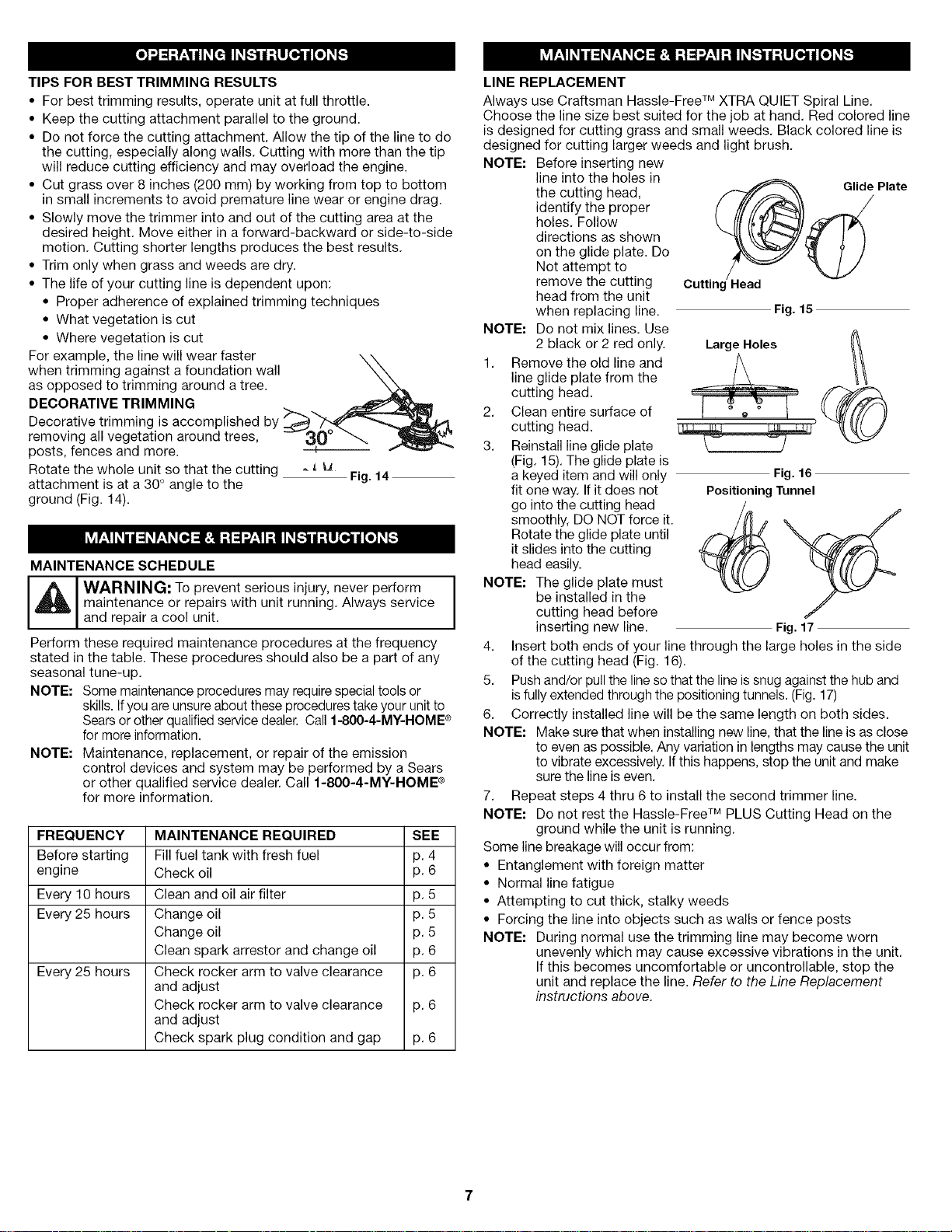
NOTE: Before inserting new
NOTE: Do not mix lines. Use
1. Remove the old line and
2. Clean entire surface of
3. Reinstall line glide plate
NOTE: The glide plate must
4. Insert both ends of your line through the large holes in the side
5. Push and/or pull the line sothat the line is snug against the hub and
6. Correctly installed line will be the same length on both sides.
NOTE: Make sure that when installing new line, that the line is as close
7. Repeat steps 4 thru 6 to install the second trimmer line.
NOTE: Do not rest the Hassle-Free TMPLUS Cutting Head on the
Some line breakage will occur from:
• Entanglement with foreign matter
• Normal line fatigue
• Attempting to cut thick, stalky weeds
• Forcing the line into objects such as walls or fence posts
NOTE: During normal use the trimming line may become worn
line into the holes in
the cutting head, Glide Plate
identify the proper
holes. Follow
directions as shown
on the glide plate. Do
Not attempt to
remove the cutting
head from the unit
when replacing line.
2 black or 2 red only.
line glide plate from the
cutting head.
cutting head.
(Fig. 15). The glide plate is
a keyed item and will only
fit one way. If it does not
go into the cutting head
smoothly, DO NOT force it.
Rotate the glide plate until
it slides into the cutting
head easily.
be installed in the
cutting head before
inserting new line. Fig. 17
of the cutting head (Fig. 16).
isfully extended through the positioning tunnels. (Fig. 17)
to even as possible. Any variation in lengths may cause the unit
to vibrate excessively. If this happens, stop the unit and make
sure the line is even.
ground while the unit is running.
unevenly which may cause excessive vibrations in the unit.
Ifthis becomes uncomfortable or uncontrollable, stop the
unit and replace the line. Refer to the Line Replacement
instructions above.
• )
.lead
Fig. 15
_ _Large Holes
Fig. 16
Positioning "runnel
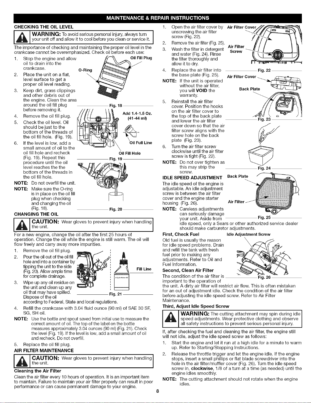
CHECKING THE OIL LEVEL
iA to vo,0se ,o°s0e sooa,, ,o . ,wa stumI
The importance of checking and maintaining the proper oil level in the
crankcase cannot be overemphasized. Check oil before each use:
1. Stop the engine and allow
2. Place the unit on a flat,
3. Keep dirt, grass clippings
4. Remove the oil fill plug.
5. Check the oil level. Oil
6. If the level is low, add a
NOTE: Do not overfill the unit.
NOTE: Make sure the O-ring
CHANGING THE OIL
J_, AUTION: Wear gloves to prevent injury when handling
For a new engine, change the oil after the first 25 hours of
operation. Change the oil while the engine is still warm. The oil will
flow freely and carry away more impurities.
1. Remove the oil fill plug.
2. Pour the oil out of the oil fill
3. Wipe up any oil residue on
4. Refill the crankcase with 3.04 fluid ounce (90 ml) of SAE 30 SE
NOTE: Use the bottle and spout saved from initial use to measure the
5. Replace the oil fill plug.
AIR FILTER MAINTENANCE
I_IL AUTION: Wear gloves to prevent injury when handling
Cleaning the Air Filter
Clean the air filter every 10 hours of operation. It is an important item
to maintain. Failure to maintain your air filter properly can result in poor
performance or can cause permanent damage to your engine.
your unit off and allow itto cool before you clean or service it.
oil to drain into the
crankcase.
level surface to get a
proper oil level reading.
and other debris out of
the engine. Clean the area
around the oil fill plug
before removing it.
should be just to the
bottom of the threads of
the oil fill hole. (Fig. 19).
small amount of oil to the
oil fill hole and recheck
(Fig. 19). Repeat this
procedure until the oil
level reaches the the
bottom of the threads in
the oil fill hole.
is in place on the oil fill
plug when checking
and changing the oil
(Fig. 18).
the unit.
hole and into a container by
tipping the unit to the side
(Fig.20).Allow ample time
for complete drainage.
the unit and clean up any
oil that may have spilled.
Dispose of the oil
according to Federal, State and local regulations.
SG, SH oil.
correct amount of oil. The top of the label on the bottle
measures approximately 3.04 ounces (90 ml) (Fig. 21). Check
the level (Fig. 19). Ifthe level is low, add a small amount of oil
and recheck. Do not overfill.
the unit.
O-Ring
Fig. 18
(41-44 ml)
_Add 1.4-1.5 Oz.
Oil Fill Hole
Fig. 19
Fig. 20
Fig. 21
OilFily Plug
II Line
Fill Line
1. Open the air filter cover by ._ri/,_
unscrewing the air filter
screw (Fig. 22).
2. Remove the air filter (Fig.25).
3. Wash the filter in detergent "*Screwr
and water (Fig. 24). Rinse
the filter thoroughly and
allow it to dry.
4. Replace the air filter into
the base plate (Fig. 25).
NOTE: Ifthe unit is operated
5. Reinstall the air filter
6. Turn the air filter screw
NOTE: Do not over tighten as
IDLE SPEED ADJUSTMENT
The idle speed of the engine is
adjustable. An idle adjustment
screw is between the air filter
cover and the engine starter
housing (Fig. 26).
NOTE: Careless adjustments
First, Check Fuel Idle Adjustment Screw
Old fuel is usually the reason
for idle speed problems. Drain
and refill the tank with fresh
fuel prior to making any
adjustments. Refer to Oil and
Fuel Information.
Second, Clean Air Filter
The condition of the air filter is _ -- Fig. 26
important to the operation of
the unit. A dirty air filter will restrict air flow. This is often mistaken
for an out of adjustment idle. Check the condition of the air filter
before adjusting the idle speed screw. Refer to Air Filter
Maintenance.
Third, Adjust Idle Speed Screw
If, after checking the fuel and cleaning the air filter, the engine still
will not idle, adjust the idle speed screw as follows:
1. Start the engine and let it run at a high idle for a minute to warm
2. Release the throttle trigger and let the engine idle. If the engine
NOTE: The cutting attachment should not rotate when the engine
without the air filter,
you will VOID the
warranty.
cover. Position the hooks
on the air filter cover to
the top of the back plate
and lower the air filter
cover down so that the air
filter screw aligns with the
screw hole on the back
plate (Fig. 23).
clockwise until the air filter
screw is tight (Fig. 22).
this may strip the
screw.
can seriously damage
your unit. Aside from
idle speed, only a Sears or other authorized service dealer
should make carburetor adjustments.
_i_1 ARNING: The cutting attachment may spin during idle I
speed adjustments. Wear protective clothing and observe
a safety nstruct ons to prevent serous persona n ury.
up. Refer to Starting/Stopping Instructions.
stops, insert a small phillips or flat blade screwdriver into the
hole in the air filter/muffler cover (Fig. 26). Turn the idle speed
screw in, cloclcwise, 1/8 of a turn at a time (as needed) until the
engine idles smoothly.
idles.
Air FilterCover
Fig.22
Air FilterCover
Back Plate
Fig. 23
Fig.24
Back Plate
Fig. 25
3. Ifthecuttingattachmentrotateswhentheengineidles,turnthe
idlespeedscrewcounterclockwise1/8ofaturnatatime(as
needed),toreduceidlespeed.
Checkingthefuel,cleaningtheairfilter,andadjustingtheidlespeed
shouldsolvemostengineproblems.Ifnotandallofthefollowing
aretrue:
• theenginewillnotidle
• theenginehesitatesorstallsonacceleration
• thereisalossofenginepower
Havethecarburetoradjustedbyanauthorizedservicedealer.
ROCKER ARM CLEARANCE
_I ARNING: TOavoid serious personal injury, alwaysturn your
This requires disassembly of the engine. If you feel unsure or
unqualified to perform this, take the unit to a Sears or other qualified
service center.
NOTE: Inspect the valve to rocker arm clearance with a feeler
• The engine must be cold when checking or adjusting the valve
• This task should be performed inside in a clean, dust free area.
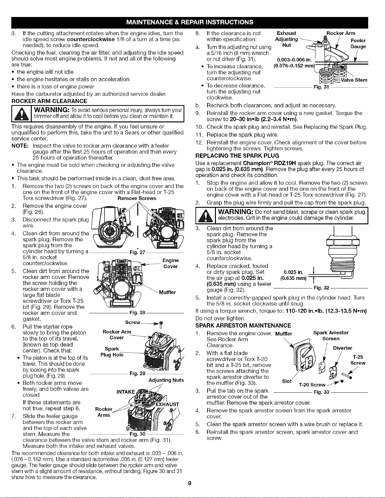
1. Remove the two (2) screws on back of the engine cover and the
2. Remove the engine cover
3. Disconnect the spark plug
4. Clean dirt from around the
5. Clean dirt from around the
6. Pull the starter rope Screw_,_,
7. Slide the feeler gauge Arms
The recommended clearance for both intake and exhaust is .003 - .006 in.
(.076 - 0.152 ram). Use a standard automotive .005 in. (0.127 mm) feeler
gauge. The feeler gauge should slide between the rocker arm and valve
stem with a slight amount of resistance, without binding. Figure30 and 31
show how to measure the clearance.
tr mmer off and a ow t to coo before you c ean or manta n t.
gauge after the first 25 hours of operation and then every
25 hours of operation thereafter.
clearance.
one on the front of the engine cover with a Flat-head or T-25
Torx screwdriver (Fig. 27). Remove Screws
(Fig. 28).
wire.
spark plug. Remove the
spark plug from the
cylinder head by turning a Fig_27
5/8 in. socket
counterclockwise. Engine
rocker arm cover. Remove
the screw holding the
rocker arm cover with a
large flat blade
screwdriver or Torx T-25
bit (Fig. 29). Remove the
rocker arm cover and Fig. 28
gasket.
slowly to bring the piston Rocker Arm
to the top of its travel, Cover
(known as top dead
center). Check that: Spark
• The piston isat the top of its Plug
travel. This should be done
by looking into the spark
plug hole. (Fig.29) Fig. 29
• Both rocker arms move
freely, and both valves are
closed
If these statements are EXHAUST
not true, repeat step 6. Rocker t_V\
between the rocker arm
and the top of each valve
stem. Measure the Fig. 30
clearance between the valve stem and rocker arm (Fig. 31).
Measure both the intake and exhaust valves.
INTAKE
Adjusting Nuts
Cover
8. If the clearance is not Exhaust Rocker Arm
within specification: Ad Feeler
a. Turn the adjusting nut using Nut Gauge
a 5/16 inch (8 ram) wrench
or nut driver (Fig. 31). 0.003-0.006 in.
• To increase clearance, (0.076-0.152 mm
turn the adjusting nut
counterclockwise.
• To decrease clearance, Fig.31
turn the adjusting nut
clockwise.
b. Recheck both clearances, and adjust as necessary.
9. Reinstall the rocker arm cover using a new gasket. Torque the
screw to 20-30 in•lb (2.2-3.4 N•m).
10. Check the spark plug and reinstall. See Replacing the Spark Plug.
11. Replace the spark plug wire.
12. Reinstall the engine cover. Check alignment of the cover before
tightening the screws. Tighten screws.
REPLACING THE SPARK PLUG
Use a replacement Champion ® RDZ19N spark plug. The correct air
gap is 0.025 in. (0.635 ram). Remove the plug after every 25 hours of
operation and check its condition.
1. Stop the engine and allow it to cool. Remove the two (2) screws
on back of the engine cover and the one on the front of the
engine cover with a Flat-head or T-25 Torx screwdriver (Fig. 27).
2. Grasp the plug wire firmly and pull the cap from the spark plug.
_ I WARNING: Do not sand blast, scrape or clean spark plug I
3. Clean dirt from around the J J
4. Replace cracked, fouled
5. Install a correctly-gapped spark plug in the cylinder head. Turn
If using a torque wrench, torque to: 110-120 in.•lb. (12.3-13.5 N•m}
Do not over tighten.
SPARK ARRESTOR MAINTENANCE
1. Remove the engine cover. Muffler Spark Arrestor
2. With a flat blade
3. Pull the tab on the spark
4. Remove the spark arrestor screen from the spark arrestor
5. Clean the spark arrestor screen with a wire brush or replace it.
6. Reinstall the spark arrestor screen, spark arrestor cover and
electrodes. Grit in the engine could damage the cylinder.
spark plug. Remove the
spark plug from the
cylinder head by turning a
5/8 in. socket
counterclockwise. ._
or dirty spark plug. Set 0.025in.
the air gap at 0.025 in. (0.635ram)
(0.635 mm) using a feeler
gauge (Fig. 32). Fig.32
the 5/8 in. socket clockwise until snug.
See Rocker Arm
Clearance.
screwdriver or Torx T-20
bit and a T-25 bit, remove
the screws attaching the
spark arrestor diverter to
the muffler (Fig. 33).
arrestor cover out of the
muffler. Remove the spark arrestor cover.
cover.
screw.
Sl°t_crew_ "+
Screen
Fig.33
Diverter
/ T-25
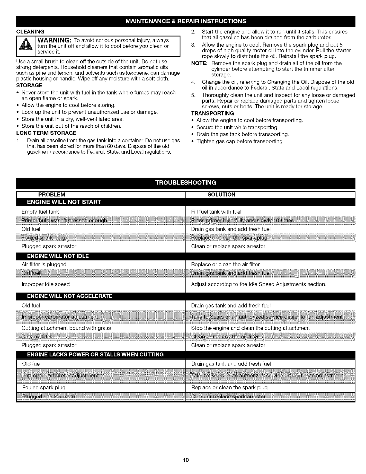
CLEANING
J_ WARNING: To avoid serious personal injury, always
Use a small brush to clean off the outside of the unit. Do not use
strong detergents. Household cleaners that contain aromatic oils
such as pine and lemon, and solvents such as kerosene, can damage
plastic housing or handle. Wipe off any moisture with a soft cloth.
STORAGE
• Never store the unit with fuel in the tank where fumes may reach
• Allow the engine to cool before storing.
• Lock up the unit to prevent unauthorized use or damage.
• Store the unit in a dry, well-ventilated area.
• Store the unit out of the reach of children.
LONG TERM STORAGE
1. Drain all gasoline from the gas tank into a container. Do not use gas
turn the unit off and allow it to cool before you clean or
service it.
an open flame or spark.
that has been stored for more than 60 days. Dispose of the old
gasoline in accordance to Federal, State, and Local regulations.
2. Start the engine and allow it to run until it stalls. This ensures
that all gasoline has been drained from the carburetor.
3. Allow the engine to cool. Remove the spark plug and put 5
drops of high quality motor oil into the cylinder. Pull the starter
rope slowly to distribute the oil. Reinstall the spark plug.
NOTE: Remove the spark plug and drain all of the oil from the
cylinder before attempting to start the trimmer after
storage.
4. Change the oil, referring to Changing the Oil. Dispose of the old
oil in accordance to Federal, State and Local regulations.
5. Thoroughly clean the unit and inspect for any loose or damaged
parts. Repair or replace damaged parts and tighten loose
screws, nuts or bolts. The unit is ready for storage.
TRANSPORTING
• Allow the engine to cool before transporting.
• Secure the unit while transporting.
• Drain the gas tank before transporting.
• Tighten gas cap before transporting.
PROBLEM
Empty fuel tank
Old fuel
Plugged spark arrestor
::1#[€11#I:::EvlvlIIIII #[e]l/I I=]II!
Air filter is plugged
Improper idle speed
:1#[€11#I:Sv_vlII II #[e]lf:Te.le.]:11:1:r£1/
Old fuel
Cutting attachment bound with grass
Plugged spark arrestor
:1_[€11_I=11l:Te.][_.1",,[elv_vj::1:[e] :1[_1f:11I_lV_vj-"I::1_[e.]ll I / I_[€
Old fuel
SOLUTION
Fill fuel tank with fuel
Drain gas tank and add fresh fuel
Clean or replace spark arrestor
Replace or clean the air filter
Adjust according to the Idle Speed Adjustments section.
Drain gas tank and add fresh fuel
Stop the engine and clean the cutting attachment
Clean or replace spark arrestor
Drain gas tank and add fresh fuel
10
 Loading...