

Craftsman 316791930 Owner’s Manual

Operator's Manual
1411N
4-Cycle
GAS TRIMMER
Model No. 316.791930
INCREDI.PULL "
UNBELIEVABLE STARTING E A S E
with MAX FIREx4clGNITICIN M
* SAFETY
* ASSEMBLY
* OPERATION
* MAINTENANCE
* PARTS LIST
* ESPANOL, R 15
CAUTION: Before using this
product, read this manual and
follow all safety rules and
operating instructions.
FOR ANSWERS TO QUESTIONS ABOUT THIS PRODUCT, CALL 1=800=235=5878
Sears, Roebuck and Co., Hoffman Estates, IL 60179, U.S.A.
Visit our website: www.sears.com/craftsman
P/N 769=04470A P01 1/09
CALiFORNiAPROPOSiTiON65WARNING
THE ENGINE EXHAUST FROM THIS PRODUCT CONTAINS
CHEMICALS KNOWN TO THE STATE OF CALiFORNiA TO CAUSE
CANCER, BIRTH DEFECTS OR OTHER REPRODUCTIVE HARM.
The purpose of safety symbols is to attract your attention to possible I
dangers. The safety symbols, and their explanations, deserve your I
careful attention and understanding. The safety warnings do not by I
themselves eliminate any danger. The instructions or warnings they I
give are not substitutes for proper accident prevention measures.
SYMBOL MEANING
TABLE OF CONTENTS
Safety Rules .......................................... 2
Warranty ............................................. 4
Know Your Unit ........................................ 4
Assembly instructions ................................... 4
Oil and Fuel information ................................. 5
Starting/Stopping instructions ............................ 5
Operating instructions ................................... 6
Maintenance and Repair instructions ....................... 7
Cleaning and Storage .................................. 10
Optional Equipment .................................... 10
Troubleshooting Chart .................................. 11
Specifications ........................................ 12
Parts List ............................................ 29
Service Numbers .............................. Back Cover
SPARK ARRESTOR NOTE
NOTE: For users on U.S. Forest Land and in the states of California,
Maine, Oregon and Washington. All U.S. Forest Land and the state of
California (Public Resources Codes 4442 and 4443), Oregon and
Washington require, by law that certain internal combustion engines
operated on forest brush and/or grass-covered areas be equipped with a
spark arrestor, maintained in effective working order, or the engine be
constructed, equipped and maintained for the prevention of fire. Check
with your state or local authorities for regulations pertaining to these
requirements. Failure to follow these requirements could subject you to
liability or a fine. This unit is factory equipped with a spark arrestor, if
it requires replacement, ask your LOCAL SERVICE DEALER to installthe
Accessory Part #753-05245 Muffler Assembly.
All information, illustrations, and specifications in this manual are based
on the latest product information available at the time of printing. We
reserve the right to make changes at any time without notice.
,, IMPORTANT SAFETY INSTRUCTIONS ,,
READ ALL INSTRUCTIONS BEFORE OPERATING
= Read the instructions carefully. Be familiar with the controls and
proper use of the unit.
• Do not operate this unit when tired, ill, or under the influence of
alcohol, drugs, or medication.
Children and teens under the age of 15 must not use the unit,
except for teens guided by an adult.
All guards and safety attachments must be installed properly
before operating the unit.
inspect the unit before use. Replace damaged parts. Check for fuel
leaks. Make sure all fasteners are in place and secure. Replace parts
that are cracked, chipped, or damaged in any way. Do not operate the
unit with loose or damaged parts.
Carefully inspect the area before starting the unit. Remove all
debris and hard or sharp objects such as glass, wire, etc.
Clear the area of children, bystanders, and pets. At a minimum, keep all
children, bystanders, and pets outside a 50 feet (15 m.) radius; there
still may be a riskto bystanders from thrown objects. Bystanders
should be encouraged to wear eye protection, if you are approached,
stop the unit immediately.
Use only Craftsman Hassle-Free TM XTRA QUIET Spiral
Lineoriginal equipment manufacturer replacement line. Never use
metal-reinforced line, wire or rope. These can break off and become
dangerous projectiles.
Squeeze the throttle control and check that itreturns automatically to
the idle position. Make all adjustments or repairs before using unit.
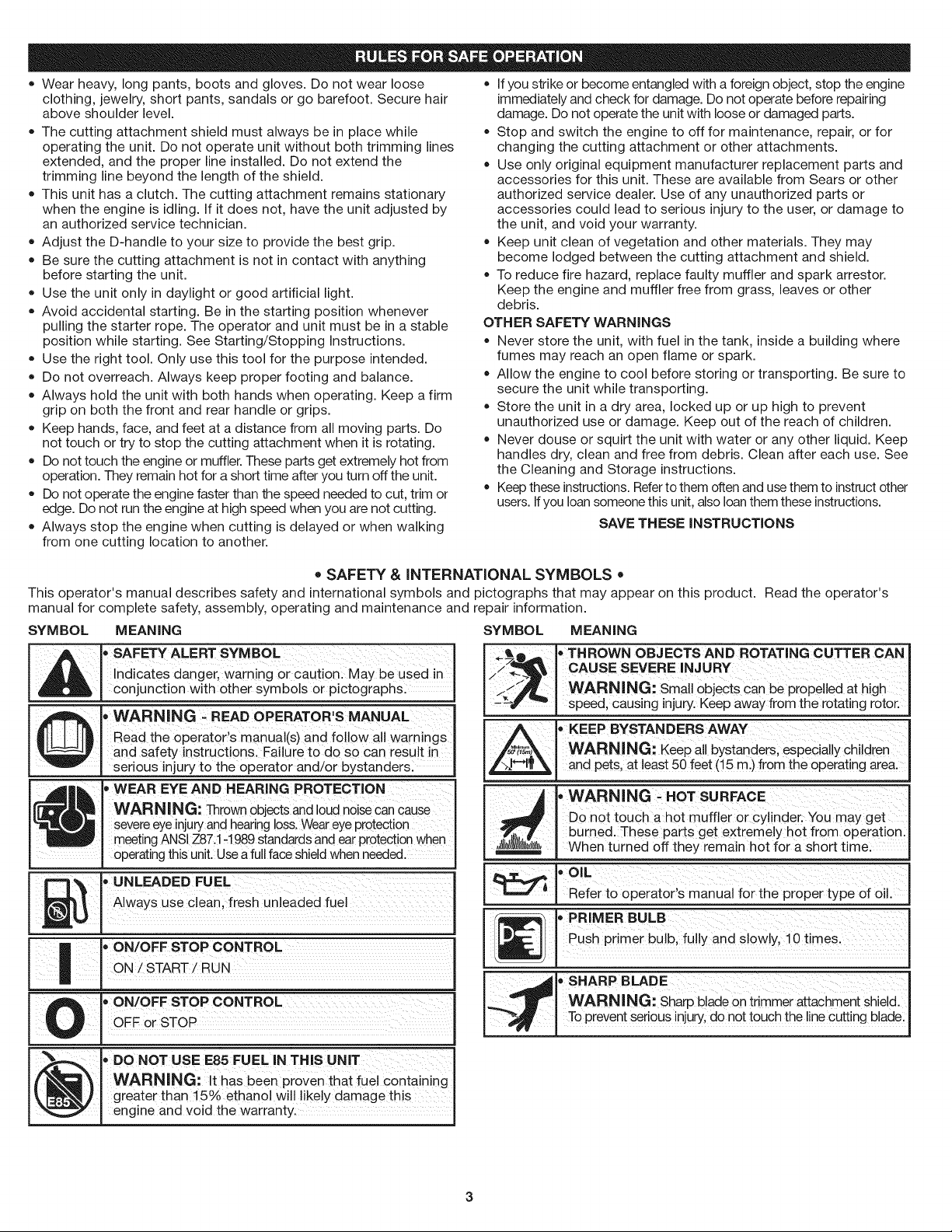
SAFETY ALERT: indicates danger, warning or caution.
Attention is required in order to avoid serious personal
injury. May be used in conjunction with other symbols or
pictographs.
NOTE: Advises you of information or instructions vital to the
I _ I DANGER: Failure to obey a safety warning will result in
NOTE- THIS UNIT IS ELECTRIC START CAPABLE as an
Read the Operator's Manual and follow all warnings and safety
instructions. Failure to do so can resultin serious injuryto the operator
and/or bystanders. FOR QUESTIONS, CALL 1-800-235-5878
SAFETY WARNINGS FOR GAS UNITS
operation or maintenance of the equipment.
serious injury to yourself or to others. Always follow the
safety precautions to reduce the risk of fire, electric shock
and personal injury.
WARNING: Failureto obey asafety warning can result ininjury to yourself and others. Always follow the safety precautions
to reduce the riskof fire,electric shock and personal injury.
CAUTION: Failure to obey a safety warning may result in
property damage or personal injury to yourself or to others.
Always follow the safety precautions to reduce the risk of fire
electric shock and personal injury.
alternate starting method. Refer to the Electric Starter
operator's manual for proper starting instructions
I A IWARNING: Gasoline is highly flammable and its vapors i
I _ I can explode if ignited. Take the following precautions:
Store fuel only in containers specifically designed and approved
for the storage of such materials.
Avoid creating asource of ignition for spilled fuel. Do not start the
engine until fuel vapors dissipate.
Always stop the engine and allow itto cool before filling the fuel tank.
Never remove the cap of the fuel tank, or add fuel, when the engine
is hot. Never operate the unit without the fuel cap securely in place.
Loosen the fuel tank cap slowly to relieve any pressure in the tank.
Add fuel in a clean, well-ventilated outdoor area where there are no
sparks or flames. Slowly remove the fuel cap only after stopping engine.
Do not smoke while fueling. Wipe up any spilled fuel from the unit
immediately.Always wipe unit dry before using.
Move the unit at least 30 feet (9.1m) from the fueling source and site
beforestarting the engine. Do not smoke orallow sparks and open
flames near the area while adding fuel oroperating the unit.
WHILE OPERATING
= Never start or run the unit inside a closed room or building. Breathing
exhaust fumes can kill. Operate this unit only ina well ventilated
outdoor area.
Be aware of the risk of injury to the head, hands and feet.
Wear safety glasses or goggles that are marked as meeting ANSI
Z87.1-1989 standards. Also wear ear/hearing protection when
operating this unit. Wear a face or dust mask if the operation isdusty.
Long sleeve shirts are recommended.
i
• Wearheavy,longpants,bootsandgloves.Donotwearloose • Ifyoustrikeorbecomeentangledwithaforeignobject,stoptheengine
clothing,jewelry,shortpants,sandalsorgobarefoot.Securehair
aboveshoulderlevel.
Thecuttingattachmentshieldmustalwaysbeinplacewhile
operatingtheunit.Donotoperateunitwithoutbothtrimminglines
extended,andtheproperlineinstalled.Donotextendthe
trimminglinebeyondthelengthoftheshield.
Thisunithasaclutch.Thecuttingattachmentremainsstationary
whentheengineisidling.Ifitdoesnot,havetheunitadjustedby
anauthorizedservicetechnician.
AdjusttheD-handletoyoursizetoprovidethebestgrip.
Besurethecuttingattachmentisnotincontactwithanything
beforestartingtheunit.
Usetheunitonlyindaylightorgoodartificiallight.
Avoidaccidentalstarting.Beinthestartingpositionwhenever
pullingthestarterrope.Theoperatorandunitmustbeinastable
positionwhilestarting.SeeStarting/StoppingInstructions.
Usetherighttool.Onlyusethistoolforthepurposeintended.
Donotoverreach.Alwayskeepproperfootingandbalance.
Alwaysholdtheunitwithbothhandswhenoperating.Keepafirm
griponboththefrontandrearhandleorgrips.
Keephands,face,andfeetatadistancefromallmovingparts.Do
nottouchortrytostopthecuttingattachmentwhenitisrotating.
Donottouchtheengineormuffler.Thesepartsgetextremelyhotfrom
operation.Theyremainhotforashorttimeafteryouturnofftheunit.
Donotoperatetheenginefasterthanthespeedneededtocut,trimor
edge.Donotruntheengineathighspeedwhenyouarenotcutting.
Alwaysstoptheenginewhencuttingisdelayedorwhenwalking
immediatelyandcheckfordamage.Donotoperatebeforerepairing
damage.Donotoperatetheunitwithlooseordamagedparts.
Stopandswitchtheenginetooffformaintenance,repair,orfor
changingthecuttingattachmentorotherattachments.
Useonlyoriginalequipmentmanufacturerreplacementpartsand
accessoriesforthisunit.TheseareavailablefromSearsorother
authorizedservicedealer.Useofanyunauthorizedpartsor
accessoriescouldleadtoseriousinjurytotheuser,ordamageto
theunit,andvoidyourwarranty.
Keepunitcleanofvegetationandothermaterials.Theymay
becomelodgedbetweenthecuttingattachmentandshield.
Toreducefirehazard,replacefaultymufflerandsparkarrestor.
Keeptheengineandmufflerfreefromgrass,leavesorother
debris.
OTHERSAFETYWARNINGS
Neverstoretheunit,withfuelinthetank,insideabuildingwhere
fumesmayreachanopenflameorspark.
Allowtheenginetocoolbeforestoringortransporting.Besureto
securetheunitwhiletransporting.
Storetheunitinadryarea,lockeduporuphightoprevent
unauthorizeduseordamage.Keepoutofthereachofchildren.
Neverdouseorsquirttheunitwithwateroranyotherliquid.Keep
handlesdry,cleanandfreefromdebris.Cleanaftereachuse.See
theCleaningandStorageinstructions.
Keeptheseinstructions.Referto them often and usethem to instruct other
users. If you loan someone this unit, also loanthem these instructions.
SAVE THESE INSTRUCTIONS
fromonecuttinglocationtoanother.
" SAFETY & INTERNATIONAL SYMBOLS "
This operator's manual describes safety and international symbols and pictographs that may appear on this product. Read the operator's
manual for complete safety, assembly, operating and maintenance and repair information.
SYMBOL MEANING
bSAFETY ALERT SYMBOL
,d L
Q
i bON/OFF STOP CONTROL
l''m
_1_ . or
Indicates danger, warning or caution. May be used in
conjunction with other symbols or pictographs.
, WARNING - READ OPERATOR'S MANUAL
Read the operator's manual(s) and follow all warnings
and safety instructions. Failure to do so can result in
serious injury to the operator and/or bystanders.
" WEAR EYE AND HEARING PROTECTION
WARNING: Thrownobjects and loud noisecan cause
severeeyeinjuryand hearingloss.Weareye protection
meetingANSIZ87.1-1989standards andear protection when
operatingthis unit. Use a fullface shield when needed.
UNLEADED FUEL
Always use clean, fresh unleaded fuel
ON /START/RUN
bON/OFF STOP CONTROL
OFF STOP
SYMBOL MEANING
_lT,_L •THROWN OBJECTS AND ROTATING CUTTER CAN
>/_-"_b _ CAUSE SEVERE INJURY
//_Y WARNING: Small 0bjectS Canbe ProPelled at high
-_f "_ speed, causing injury. Keep away from the rotating rotor.
_,,_ • KEEP BYSTANDERS AWAY
_r_5_ WARNING: Keep a!l bystanders, especially children
t..,,,,! , Refer to operator s manual for the proper type of 0il.
_ ,, SHARP BLADE
-._ WARNING:sharp blade Ontrimmer attachment Shield.
_. To prevent serious injury,dOnot touc h the !inecutting blade:
and pets, at least 50 feet (!5 m.)from the operating area,
WARNING _HOT SURFACE
Bonot toUCh ahot muffler or CYl!nder. You may get
burned. These parts get extremely hot from operationl
When turned off they remain hot for a short time:
,,OIL
Push primer- bUlb, fu!!y and Slowly, 1o times:
,_PRIMER BULB
WARNING: It has been proven that fuel containing
(_ ' DO NOT USE E85 FUEL IN THiS UNIT
greater than 15% ethanol will likely damage this
engine and void the warranty.
3
CRAFTSMAN FULL WAR RANTY
If this Craftsman product fails due to a defect in material or workmanship within two years from the date of purchase, return itto any Sears
store, Parts and Repair Service Center, or other Craftsman outlet in the United States for free repair (or replacement if repair proves impossible).
This warranty applies for only 90 days if this product is ever used for commercial or rental purposes.
This warranty covers ONLY defects in material and workmanship. Sears will NOT pay for:
• Expendable items that can wear out from normal use within the warranty period, such as cutting line, air cleaner or spark plug.
• Repairs necessary because of accident or failure to operate or maintain the product according to all supplied instructions.
• Preventive maintenance, or repairs necesary due to improper fuel mixture, contaminated or stale fuel.
This warranty gives you specific legal rights, and you may also have other rights which vary from state to state.
Sears, Roebuck and Co., Hoffman Estates, IL 60179
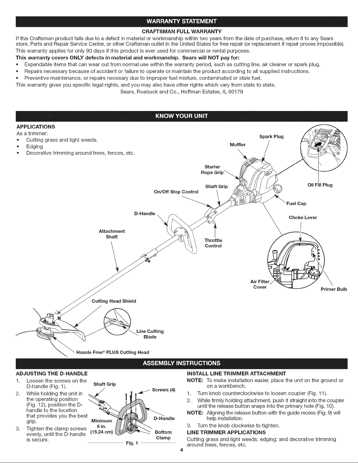
APPLICATIONS
As a trimmer:
• Cutting grass and light weeds.
Spark Plug
• Edging Muffler
Decorative trimming around trees, fences, etc.
Starter
Rope Grip_
D=Handle
Attachment
Shaft
Cutting Head Shield
Line Cutting
Blade
Hassle FreeRPLUS Cutting Head
®
On/Off Stop Control
Shaft Grip
Throttle
Control
Air Filter
Cover
Fuel Cap
Choke Lever
Primer Bulb
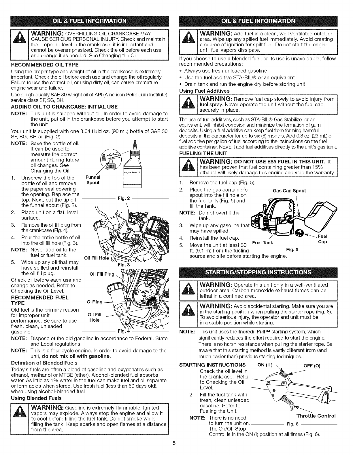
ADJUSTING THE D-HANDLE
1. Loosen the screws on the
D-handle (Fig. 1). Shaft Grip
2. While holding the unit in _-.,_TJ
the operating position
(Fig. 12), position the D-
handle to the location
that provides you the best
grip. ,v,,;,,in.U,,, _
3. Tighten the clamp screws
evenly, until the D-handle
is secure.
I_mndle
Fig. 1
Screws (4)
Bottom
Clamp
INSTALL LINE TRIMMER ATTACHMENT
NOTE: To make installation easier, place the unit on the ground or
on a workbench.
1. Turn knob counterclockwise to loosen coupler (Fig. 11).
2. While firmly holding attachment, push it straight into the coupler
until the release button snaps into the primary hole (Fig. 10).
NOTE: Aligning the release button with the guide recess (Fig. 9) will
help installation.
3. Turn the knob clockwise to tighten.
LINE TRIMMER APPLICATIONS
Cutting grass and light weeds; edging; and decorative trimming
around trees, fences, etc.
WARNING:
,_1 OVERFiLLiNG OiL CRANKCASE MAY
I CAUSE SERIOUS PERSONAL iNJURY. Check and maintain
I the proper oil level in the crankcase; it is important and
I cannot be overemphasized. Check the oil before each use
and change t as needed. See Chang ng the O.
RECOMMENDED OiL TYPE
Using the proper type and weight of oil in the crankcase isextremely
important. Check the oil before each use and change the oil regularly.
Failure to use the correct oil, or using dirty oil, can cause premature
engine wear and failure.
Use ahigh-quality SAE 30 weight oil of API (American Petroleum institute)
service chss SF,SG, SH.
ADDING OIL TO CRANKCASE: INITIAL USE
NOTE: This unit is shipped without oil. in order to avoid damage to
the unit, put oil in the crankcase before you attempt to start
the unit.
Your unit is supplied with one 3.04 fluid oz. (90 ml.) bottle of SAE 30
SF, SG, SH oil (Fig. 2).
NOTE: Save the bottle of oil.
1. Unscrew the top of the
2. Place unit on a flat, level
3. Remove the oil fill plug from
4. Pour the entire bottle of oil
NOTE: Never add oil to the
5. Wipe up any oil that may Fig. 3
Check oil before each use and
change as needed. Refer to
Checking the Oil Level.
RECOMMENDED FUEL
TYPE O=Ring
Old fuel is the primary reason
for improper unit oil Fill
performance. Be sure to use Hole
fresh, clean, unleaded
gasoline. Fig. 4
NOTE: Dispose of the old gasoline in accordance to Federal, State
NOTE: This is a four cycle engine, in order to avoid damage to the
Definition of Blended Fuels
Today's fuels are often a blend of gasoline and oxygenates such as
ethanol, methanol or MTBE (ether). Alcohol-blended fuel absorbs
water. As little as 1% water in the fuel can make fuel and oil separate
or form acids when stored. Use fresh fuel (less than 60 days old),
when using alcohol-blended fuel.
Using Blended Fuels
it can be used to
measure the correct
amount during future
oil changes. See
Changing the Oil.
bottle of oil and remove
the paper seal covering
the opening. Replace the
top. Next, cut the tip off
the funnel spout (Fig. 2).
surface.
the crankcase (Fig.4).
into the oil fill hole (Fig. 3).
fuel or fuel tank.
have spilled and reinstall
the oil fill plug. Oil Fill Plug
and Local regulations.
unit, do not mix oil with gasoline.
Oil Fill Hole
Fig. 2
WARNING: Gasoline is extremely flammable, ignited
vapors may explode. Always stop the engine and allow it
to cool before filling the fuel tank. Do not smoke while
filling the tank. Keep sparks and open flames at a distance
from the area.
area. Wipe up any spilled fuel immediately. Avoid creating
_L_J ARNING: Add fuel in a clean, well ventilated outdoor
if you choose to use a blended fuel, or its use is unavoidable, follow
recommended precautions:
• Always use fresh unleaded gasoline
Using Fuel Additives
_[_ ARNING: Remove fuel cap slowly to avoid injury from
The use of fuel additives, such as STA-BIL@ Gas Stabilizer or an
equivalent, will inhibit corrosion and minimize the formation of gum
deposits. Using a fuel additive can keep fuel from forming harmful
deposits inthecarburetor for up to six (6) months. Add 0.8oz. (23 ml.) of
fuel additive per gallon of fuel according to the instructionson the fuel
additive container. NEVER add fuel additives directly to the unit's gas tank.
FUELING THE UNIT
_ ARNING: DO NOT USE E85 FUEL IN THIS UNIT. It
1. Remove the fuel cap (Fig. 5).
2. Place the gas container's
NOTE: Do not overfill the
3. Wipe up any gasoline
4. Reinstall the fuel cap.
5. Move the unit at least 30 FueITank
a source of ignition for spilt fuel. Do not start the engine
until fuel vapors dissipate.
Use the fuel additive STA-BIL® or an equivalent
Drain tank and run the engine dry before storing unit
fuel spray. Never operate the unit without the fuel cap
securely in place.
has been proven that fuel containing greater than 15%
ethanol will likely damage this engine and void the warranty.
Gas Can Spout
spout into the fill hole on
the fuel tank (Fig. 5) and
fill the tank.
tank.
may have spilled.
Fuel
Cap
ft. (9.1 m) from the fueling Fig. 5
source and site before starting the engine.
_, ARNING: Operate this unit only in a well-ventilatedoutdoor area. Carbon monoxide exhaust fumes can be
lethal in a confined area.
,_ WARNING: Avoid accidental starting. Make sure you are
NOTE: This unit uses the Incredi=PulF Mstarting system, which
STARTING INSTRUCTIONS
5
in the starting position when pulling the starter rope (Fig. 8).
Toavoid serious injury, the operator and unit must be
in a stable position while starting.
significantly reduces the effort required to start the engine.
There is no harsh resistance when pulling the starter rope. Be
aware that this starting method is vastly different from (and
much easier than) previous starting techniques.
1. Check the oil level in
the crankcase. Refer
to Checking the Oil
Level.
2. Fill the fuel tank with
fresh, clean unleaded
gasoline. Refer to
Fueling the Unit.
NOTE: There is no need
to turn the unit on. Fig. 6
The On/Off Stop
Control is in the ON (I)position at all times (Fig. 6).
Throttle Control
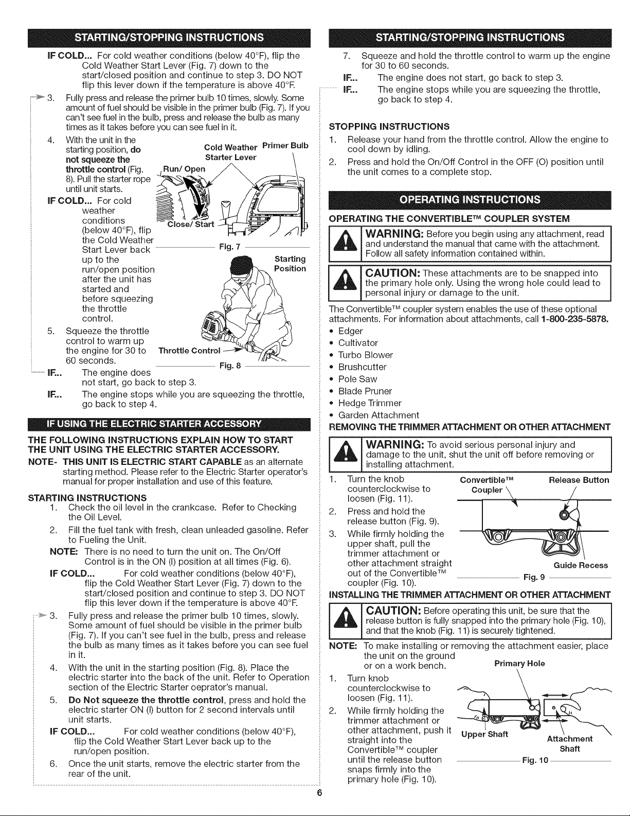
IFCOLD...Forcoldweatherconditions(below40°F),flipthe
ColdWeatherStartLever(Fig.7)downtothe
start/closedpositionandcontinuetostep3.DONOT
flipthisleverdownifthetemperatureisabove40°R
3. Fullypressandreleasetheprimerbulb10times,slowly.Some
amountoffuelshouldbevisibleintheprimerbulb(Fig.7).Ifyou
can'tseefuelinthebulb,pressandreleasethebulbasmany
timesasittakesbeforeyoucanseefuelinit.
4. Withtheunitinthe
startingposition,do
notsqueezethe
throttlecontrol(Fig.
Run/Open
Cold Weather Primer Bulb
Starter Lever
8).Pullthestarterrope
untilunitstarts.
IFCOLD...Forcold
weather
conditions
Close/Start
(below40°F),flip
theColdWeather
StartLeverback
uptothe
run/openposition
Fig. 7
Starting
Position
aftertheunithas
startedand
beforesqueezing
thethrottle
control.
5. Squeeze the throttle
control to warm up
the engine for 30 to
60 seconds.
IF...
IF... The engine stops while you are squeezing the throttle,
THE FOLLOWING iNSTRUCTiONS EXPLAIN HOW TO START
THE UNiT USING THE ELECTRIC STARTER ACCESSORY.
NOTE= THIS UNiT IS ELECTRIC START CAPABLE as an alternate
STARTING iNSTRUCTiONS
1. Check the oil level in the crankcase. Refer to Checking
2. Fill the fuel tank with fresh, clean unleaded gasoline. Refer
NOTE: There is no need to turn the unit on. The On/Off
IF COLD... For cold weather conditions (below 40°F),
4. With the unit in the starting position (Fig. 8). Place the
5. Do Not squeeze the throttle control, press and hold the
IF COLD... For cold weather conditions (below 40°F),
6. Once the unit starts, remove the electric starter from the
The engine does
not start, go back to step 3.
go back to step 4.
starting method. Please refer to the Electric Starter operator's
manual for proper installation and use of this feature.
the Oil Level.
to Fueling the Unit.
Control is in the ON (I)position at all times (Fig. 6).
flip the Cold Weather Start Lever (Fig. 7) down to the
start/closed position and continue to step 3. DO NOT
flip this lever down if the temperature is above 40°R
Fully press and release the primer bulb 10 times, slowly.
Some amount of fuel should be visible in the primer bulb
(Fig. 7). Ifyou can't see fuel in the bulb, press and release
the bulb as many times as it takes before you can see fuel
in it.
electric starter into the back of the unit. Refer to Operation
section of the Electric Starter oeprator's manual.
electric starter ON (I) button for 2 second intervals until
unit starts.
flip the Cold Weather Start Lever back up to the
run/open position.
rear of the unit.
Fig. 8
7.
Squeeze and hold the throttle control to warm up the engine
for 30 to 60 seconds.
IF...
i.............IF...
STOPPING iNSTRUCTiONS
1. Release your hand from the throttle control. Allow the engine to
2. Press and hold the On/Off Control in the OFF (O) position until
OPERATING THE CONVERTIBLE TM COUPLER SYSTEM
The engine does not start, go back to step 3.
The engine stops while you are squeezing the throttle,
go back to step 4.
cool down by idling.
the unit comes to a complete stop.
WARNING: Before you begin using any attachment, read I
and understand the manual that came with the attachment.
CAUTION: These attachments are to be snapped into i
the primary hole only. Using the wrong hole could lead to
personal injury or damage to the unit.
The Convertible TM coupler system enables the use of these optional
attachments. For information about attachments, call 1=800=235=5878.
• Edger
Cultivator
Turbo Blower
Brushcutter
Pole Saw
Blade Pruner
Hedge Trimmer
Garden Attachment
REMOVING THE TRIMMER ATTACHMENT OR OTHER ATTACHMENT
damage to the unit, shut the unit off before removing or
WARNING: To avoid serious personal injury and
installing attachment.
1. Turn the knob Convertible TM Release Button
counterclockwise to Co_, ___
loosen (Fig. 11).
2. Press and hold the J " _-_
release button (Fig. 9).
3. While firmly holding the
upper shaft, pull the
trimmer attachment or
other attachment straight Guide Recess
out of the Convertible TM Fig.9
coupler (Fig. 10).
iNSTALLING THE TRIMMER ATTACHMENT OR OTHER ATTACHMENT
_ AUTION: Before operating this unit, be sure that the
NOTE: To make installing or removing the attachment easier, place
1.
2.
6
release button is fully snapped into the primary hole (Fig. 10),
and that the knob (Fig.11) is securely tightened.
the unit on the ground
or on a work bench. Primary Hole
counterclockwise to
Turn knob "f_"_-,-_ _.__,
loosen (Fig. 11).
trimmer attachment or
While firmly holding the _ ,___
other attachment, push it Upper Shaft
straight into the Attachment
Convertible TM coupler Shaft
until the release button Fig. 10
snaps firmly into the
primary hole (Fig. 10).
1 "_ w/F
!Follow allsafety information contained within.
I
NOTE:Aligningtherelease
90° Edging Hole
buttonwiththeguide
recesswillhelp
installation(Fig.9).
3. Turntheknobclockwise
totighten(Fig.11).
NOTE:Whenusingtheline
trimmerorother
(Trimmj__-_-._ Knob
attachmenttoedge,
locktheattachment
releasebuttoninto
Fig. 11
the90°hole(Fig.11).
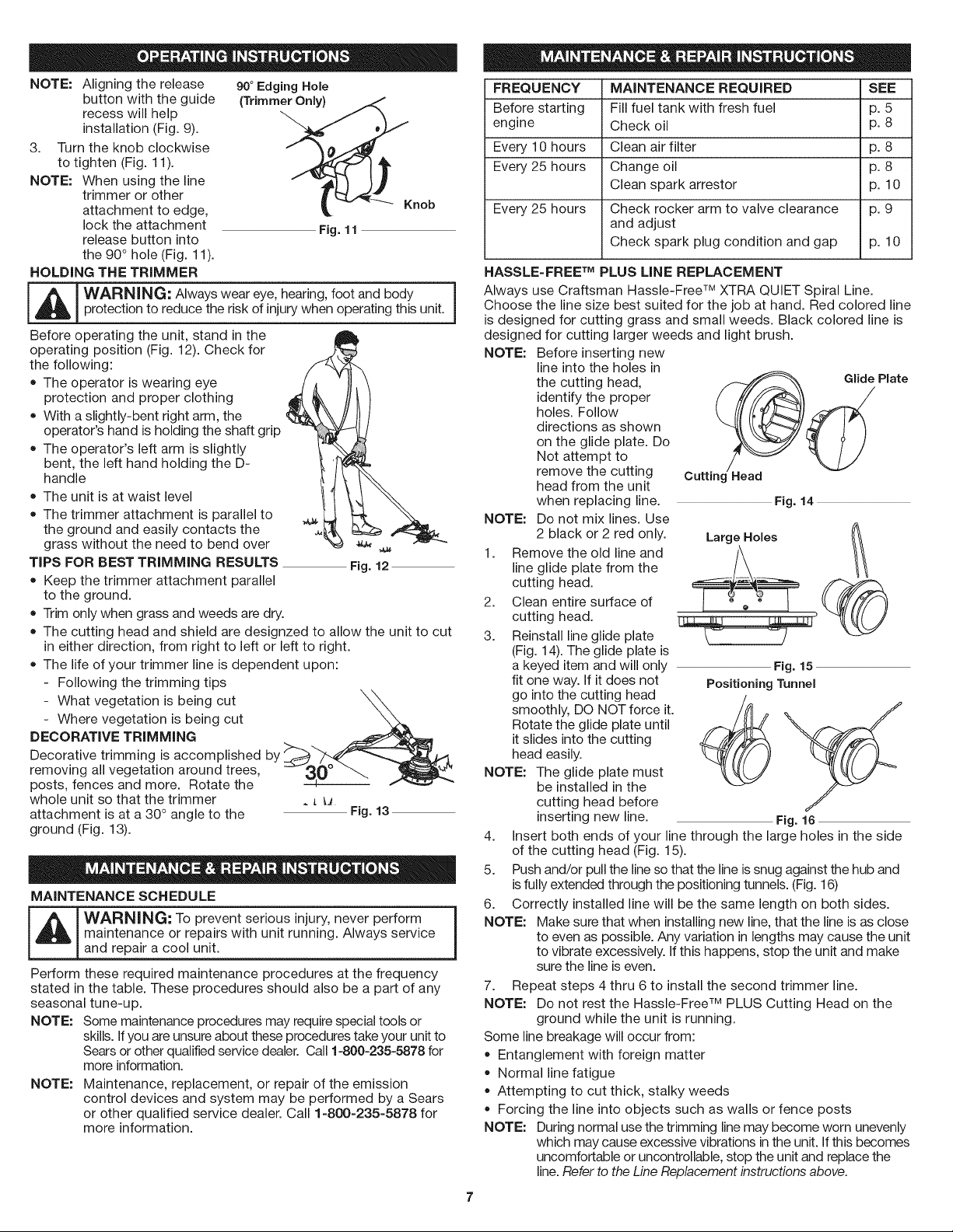
HOLDING THE TRIMMER
m
I A I WARNING: Always wear eye, hearing, foot and body
protection to reduce the risk of injury when operating this unit. j
Before operating the unit, stand in the
operating position (Fig. 12). Check for
the following:
• The operator is wearing eye
protection and proper clothing
With aslightly-bent right arm, the
operator's hand is holding the shaft grip
The operator's left arm is slightly
bent, the left hand holding the D-
handle
The unit is at waist level
The trimmer attachment is parallel to
the ground and easily contacts the
grass without the need to bend over _ ,_
TiPS FOR BEST TRiMMiNG RESULTS Fig. 12
• Keep the trimmer attachment parallel
to the ground.
Trim only when grass and weeds are dry.
The cutting head and shield are designzed to allow the unit to cut
in either direction, from right to left or left to right.
The life of your trimmer line is dependent upon:
- Following the trimming tips
- Where vegetation is being cut
DECORATIVE TRiMMiNG
- What vegetation is being cut _ _
Decorative trimming is accomplished by
removing all vegetation around trees, 30 _ _ _
posts, fences and more. Rotate the
whole unit so that the trimmer _ L _
attachment is at a 30° angle to the Fig. 13
ground (Fig. 13).
MAINTENANCE SCHEDULE
_IL[d_lL [ WARNING: T° prevent seri°us injury' never perf°rm 1
Perform these required maintenance procedures at the frequency
stated in the table. These procedures should also be a part of any
seasonal tune-up.
NOTE: Some maintenance procedures may requirespecial tools or
NOTE: Maintenance, replacement, or repair of the emission
maintenance or repairs with unit running. Always service
and repair a cool unit.
skills. Ifyou are unsure about these procedures take your unit to
Sears or other qualified service dealer. Call 1=800-235=5878for
more information.
control devices and system may be performed by a Sears
or other qualified service dealer. Call 1-800-235-5878 for
more information.
FREQUENCY MAINTENANCE REQUIRED SEE
Before starting Fill fuel tank with fresh fuel p. 5
engine Check oil p. 8
Every 10 hours Clean air filter p. 8
Every 25 hours Change oil p. 8
Clean spark arrestor p. 10
Every 25 hours Check rocker arm to valve clearance p. 9
and adjust
Check spark plug condition and gap p. 10
HASSLE-FREE TM PLUS LiNE REPLACEMENT
Always use Craftsman Hassle-Free TM XTRA QUIET Spiral Line.
Choose the line size best suited for the job at hand. Red colored line
is designed for cutting grass and small weeds. Black colored line is
designed for cutting larger weeds and light brush.
NOTE: Before inserting new
NOTE: Do not mix lines. Use
2. Clean entire surface of
1. Remove the old line and _/\ (_
3. Reinstall line glide plate
NOTE: The glide plate must
4. insert both ends of your line through the large holes in the side
5. Push and/or pull the line so that the line issnug against the hub and
6. Correctly installed line will be the same length on both sides.
NOTE: Make sure that when installing new line, that the line is as close
7. Repeat steps 4 thru 6 to install the second trimmer line.
NOTE: Do not rest the Hassle-Free TM PLUS Cutting Head on the
Some line breakage will occur from:
NOTE: During normal usethe trimming line may become worn unevenly
line into the holes in
the cutting head, Glide Plate
identify the proper
holes. Follow
directions as shown
on the glide plate. Do
Not attempt to
remove the cutting Cutting -lead
head from the unit
when replacing line. Fig. 14
2 black or 2 red only. Large Holes
line glide plate from the
cutting head.
cutting head.
(Fig. 14). The glide plate is
a keyed item and will only Fig. 15
fit one way. If it does not PositioningTunnel
go into the cutting head
smoothly, DO NOT force it.
Rotate the glide plate until
it slides into the cutting
head easily.
be installed in the
cutting head before
inserting new line. Fig. 16
of the cutting head (Fig. 15).
isfully extended through the positioning tunnels. (Fig. 16)
to even as possible. Any variation in lengths may cause the unit
to vibrate excessively. Ifthis happens, stop the unit and make
sure the line is even.
ground while the unit is running.
Entanglement with foreign matter
Normal line fatigue
Attempting to cut thick, stalky weeds
Forcing the line into objects such as walls or fence posts
which may cause excessive vibrations in the unit. If this becomes
uncomfortable or uncontrollable, stop the unit and replace the
line.Refer to theLine Replacement instructions above.
CHECKING THE OIL LEVEL
-- i[_ WARNING: To avoid serious personal injury, always turnyour unit off and allow it to cool before you clean or service it.
The importance of checking and maintaining the proper oil level in the
crankcase cannot be overemphasized. Check oil before each use:
1. Stop the engine and allow
oil to drain into the
crankcase.
2. Place the engine on a flat,
level surface with the
cutting head shield f
hanging off a work bench
or table to get a proper oil
level reading (Fig. 17).
3. Keep dirt, grass clippings
and other debris out of the
engine. Clean the area
around the oil fill plug
before removing it.
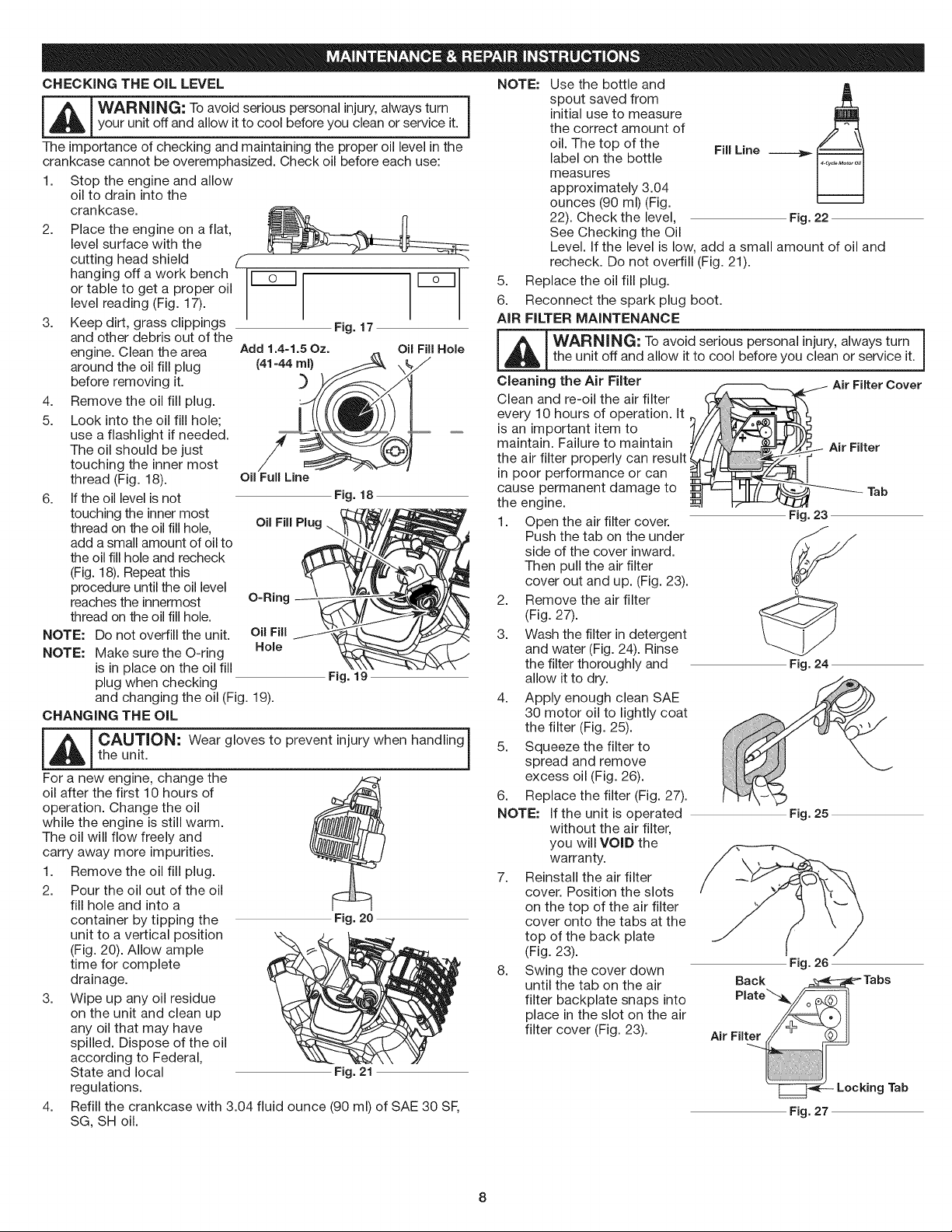
4. Remove the oil fill plug.
5. Look into the oil fill hole;
use a flashlight if needed.
The oil should be just
touching the inner most
thread (Fig. 18).
6. If the oil level is not
touching the inner most
thread on the oil fill hole,
add asmall amount of oil to
the oil fill hole and recheck
(Fig. 18). Repeat this
procedure until the oil level
reaches the innermost O=Ring
thread on the oil fill hole.
NOTE: Do not overfill the unit. Oil Fill
NOTE: Make sure the O-ring Hole
is in place on the oil fill
plug when checking
and changing the oil (Fig. 19).
CHANGING THE OIL
-- j
L_ AUTION: Wear gloves to prevent injury when handling
For a new engine, change the ?<:Z
oil after the first 10 hours of
operation. Change the oil
while the engine is still warm.
The oil will flow freely and
carry away more impurities.
1. Remove the oil fill plug.
2. Pour the oil out of the oil
3. Wipe up any oil residue
4,
the unit.
fill hole and into a
container by tipping the Fig. 20
unit to a vertical position
(Fig. 20). Allow ample
time for complete
drainage.
on the unit and clean up
any oil that may have
spilled. Dispose of the oil
according to Federal,
State and local Fig. 21
regulations.
Refill the crankcase with 3.04 fluid ounce (90 ml) of SAE 30 SF,
SG, SH oil.
Add 1.4=1.5Oz. Oil Fill Hole
Oil Full Line
Oil Fill Plug
Fig. 17
Fig. 18
Fig. 19
NOTE:
5. Replace the oil fill plug.
6. Reconnect the spark plug boot.
AIR FILTER MAINTENANCE
Use the bottle and
spout saved from
initial use to measure
the correct amount of
oil. The top of the FillLine
label on the bottle
measures
approximately 3.04
ounces (90 ml) (Fig.
22). Check the level, Fig. 22
See Checking the Oil
Level. If the level is low, add a small amount of oil and
recheck. Do not overfill (Fig. 21).
_ WARNING: To avoid serious personal injury, always turnthe unit off and allow it to cool before you clean or service it.
Cleaning the Air Filter Air Filter Cover
Clean and re-oil the air filter
every 10 hours of operation. It
is an important item to
maintain. Failure to maintain
the air filter properly can result
in poor performance or can
cause permanent damage to
the engine.
1. Open the air filter cover.
Push the tab on the under
side of the cover inward.
Then pull the air filter
cover out and up. (Fig. 23).
2. Remove the air filter
(Fig. 27).
3. Wash the filter in detergent
and water (Fig. 24). Rinse
the filter thoroughly and
allow it to dry.
4. Apply enough clean SAE
30 motor oil to lightly coat
the filter (Fig. 25).
5. Squeeze the filter to
spread and remove
excess oil (Fig. 26).
6. Replace the filter (Fig. 27).
NOTE: If the unit is operated
without the air filter,
you will VOID the
warranty.
7. Reinstall the air filter
cover. Position the slots
on the top of the air filter
cover onto the tabs at the
top of the back plate
(Fig. 23).
8. Swing the cover down
until the tab on the air
filter backplate snaps into
place in the slot on the air
filter cover (Fig. 23).
Air Filter
Tab
Fig. 23
Fig. 24
Fig. 25
Fig. 26
Fig. 27
iDLE SPEED ADJUSTMENT
The idle speed of the engine is adjustable. An idle adjustment screw
is between the air filter cover and the engine starter housing (Fig. 28).
NOTE: Careless adjustments can seriously damage the unit. Aside
from idle speed, only a Sears or other qualified service
dealer should make carburetor adjustments.
First, Check Fuel
Old fuel is usually the reason for improper unit performance. Drain
and refill the tank with fresh fuel prior to making any adjustments.
Refer to Oil and Fuel Information.
Second, Clean Air Filter
The condition of the air filter is important to the operation of the unit.
A dirty air filter will restrict air flow. This is often mistaken for an out
of adjustment carburetor. Check the condition of the air filter before
adjusting the idle speed screw. Refer to Air Filter Maintenance.
Third, Adjust Idle Speed Screw
_WARNING: The cutting attachment may spin during idle
speed adjustments. Wear protective clothing and observe I
all safety instructions to prevent serious personal injury, j
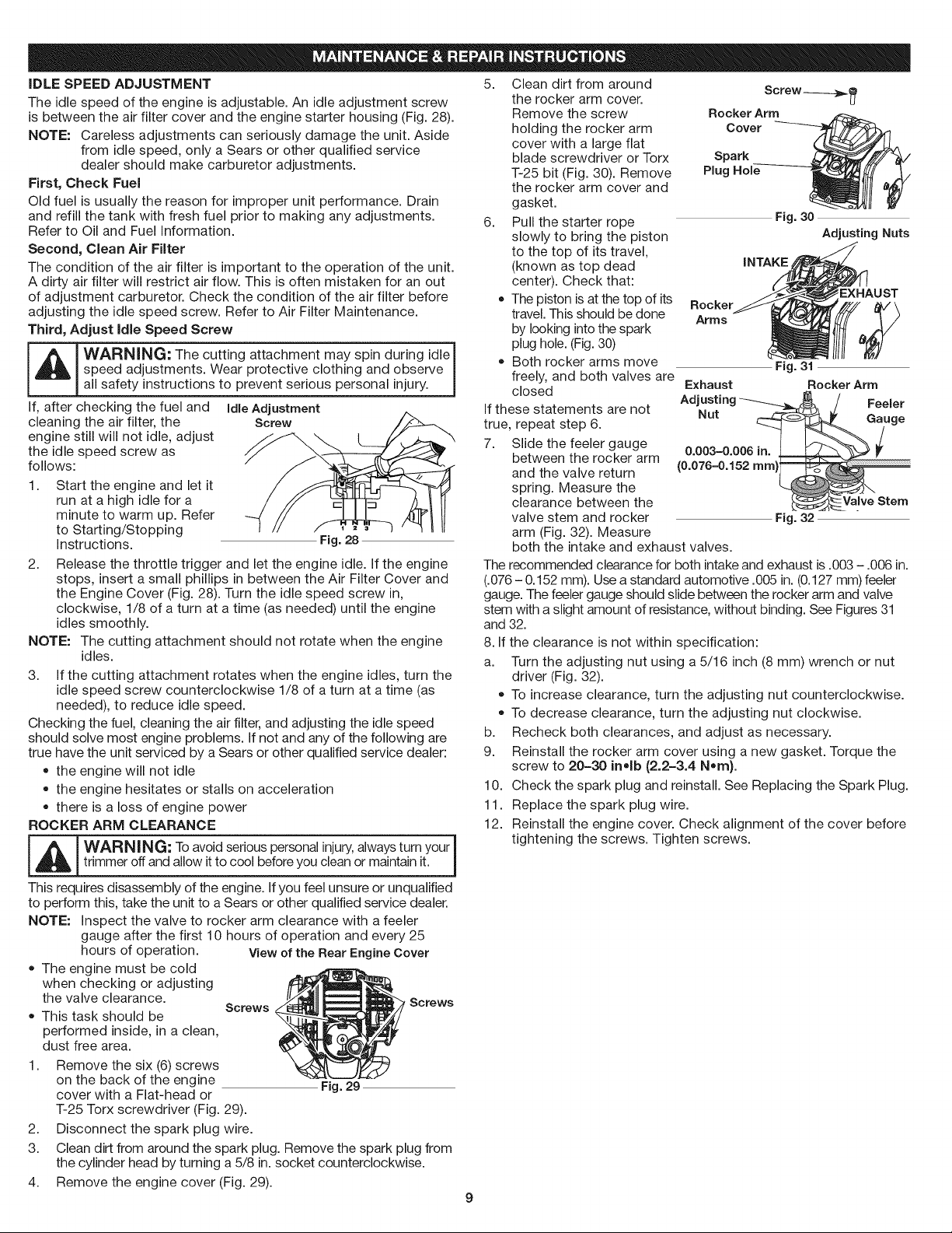
If, after checking the fuel and Idle Adjustment
cleaning the air filter, the Screw
engine still will not idle, adjust
the idle speed screw as
follows:
1.
Start the engine and let it
run at a high idle for a
minute to warm up. Refer
to Starting/Stopping
Instructions.
2. Release the throttle trigger and let the engine idle. If the engine
stops, insert a small phillips in between the Air Filter Cover and
the Engine Cover (Fig. 28). Turn the idle speed screw in,
clockwise, 1/8 of a turn at a time (as needed) until the engine
idles smoothly.
NOTE: The cutting attachment should not rotate when the engine
idles.
3. If the cutting attachment rotates when the engine idles, turn the
idle speed screw counterclockwise 1/8 of a turn at a time (as
needed), to reduce idle speed.
Checking the fuel, cleaning the air filter, and adjusting the idle speed
should solve most engine problems. If not and any of the following are
true have the unit serviced by a Sears or other qualified service dealer:
• the engine will not idle
the engine hesitates or stalls on acceleration
there is a loss of engine power
ROCKER ARM CLEARANCE
WAR NING: Toavoid serious personal injury,always turn your I
trimmer off and allow it to cool before you clean or maintain it. J
This requires disassembly of the engine. Ifyou feel unsure or unqualified
to perform this, take the unit to a Sears or other qualified service dealer.
NOTE: inspect the valve to rocker arm clearance with a feeler
gauge after the first 10 hours of operation and every 25
hours of operation. View of the Rear Engine Cover
, The engine must be cold
when checking or adjusting
the valve clearance. Screws Screws
This task should be
performed inside, in a clean,
dust free area.
1. Remove the six (6)screws
on the back of the engine
cover with a Flat-head or
T-25 Torx screwdriver (Fig. 29).
2. Disconnect the spark plug wire.
3. Clean dirt from around the spark plug. Remove the spark plug from
the cylinder head by turning a 5/8 in.socket counterclockwise.
4. Remove the engine cover (Fig. 29).
Fig. 28
Fig. 29
5. Clean dirt from around
the rocker arm cover.
Remove the screw
holding the rocker arm
RockerArm
SC few ------_}B_
Cover
cover with a large flat
blade screwdriver or Torx
T-25 bit (Fig. 30). Remove
Spark
Plug Hole
the rocker arm cover and
gasket.
6. Pull the starter rope
slowly to bring the piston
to the top of its travel,
(known as top dead
center). Check that:
• The piston isat the top of its
travel. This should bedone
by looking into the spark
Rocker
Arms
Fig. 30
Adjusting Nuts
iNTAKE
EXHAUST
plug hole. (Fig.30)
Both rocker arms move
freely, and both valves are
closed
If these statements are not
true, repeat step 6.
7. Slide the feeler gauge
between the rocker arm
and the valve return
spring. Measure the
clearance between the
valve stem and rocker
Exhaust Rocker Arm
Adjusting "-_---_J_ / Feeler
Nut _ Gauge
0.003-0.006 in__ _
(0.076-0.152 ram)
Fig. 31
Valve Stem
Fig. 32
arm (Fig. 32). Measure
both the intake and exhaust valves.
The recommended clearance for both intake and exhaust is .003 - .006 in.
(.076 - 0.152 mm). Usea standard automotive .005 in.(0.127 mm) feeler
gauge. The feeler gauge should slide between the rocker arm and valve
stem with a slight amount of resistance, without binding. See Figures 31
and 32.
8. If the clearance is not within specification:
a. Turn the adjusting nut using a 5/16 inch (8 mm) wrench or nut
driver (Fig. 32).
To increase clearance, turn the adjusting nut counterclockwise.
To decrease clearance, turn the adjusting nut clockwise.
b. Recheck both clearances, and adjust as necessary.
9. Reinstall the rocker arm cover using a new gasket. Torque the
screw to 20-30 in°lb (2.2-3.4 N,m).
10. Check the spark plug and reinstall. See Replacing the Spark Plug.
11. Replace the spark plug wire.
12. Reinstall the engine cover. Check alignment of the cover before
tightening the screws. Tighten screws.
9
REPLACING THE SPARK PLUG
Use a replacement Champion ®#RDZ19H spark plug. The correct
air gap is 0.025 in. (0.635 ram.}. Remove the plug after every 25
hours of operation and check its condition.
1. Stop the engine and allow it to cool. Remove the six (6) screws
on the back of the engine cover with a Flat-head or -I--25Torx
screwdriver (Fig. 29).
2. Grasp the plug wire firmly and pull the cap from the spark plug.
-- i_[_ ARNING: Do not sand blast, scrape or clean spark plugelectrodes. Grit in the engine could damage the cylinder.
3.
Clean dirt from around
the spark plug. Remove
the spark plug from the
cylinder head by turning a
5/8 in. socket
counterclockwise.
4.
Replace cracked, fouled
or dirty spark plug. Set
the air gap at 0.025 in.
(0.635 ram) using a feeler
gauge (Fig. 33).
5. Install a correctly-gapped spark plug in the cylinder head. Turn
the 5/8 in. socket clockwise until snug.
If using a torque wrench torque to: 110-120 in.olb. (12.3-13.5 Nora}
Do not over-tighten.
SPARK ARRESTOR MAINTENANCE
1.
Remove the rear engine cover. See Rocker Arm Clearance.
2.
With a flat blade screwdriver or Torx -I--20bit and a T-25 bit,
remove the screws attaching the spark arrestor cover to the
muffler (Fig. 39). Muffler Spark Arrestor
3. Pull the tab on the spark
arrestor cover out of the
muffler. Remove the spark
arrestor cover.
4. Remove the spark
arrestor screen from the
spark arrestor cover.
5. Clean the spark arrestor
screen with a wire brush
or replace it.
6. Reinstall the spark arrestor screen, spark arrestor cover and
screws.
CLEANING
_ WARNING: To avoid serious personal injury, always |
Use a small brush to clean off the outside of the unit. Do not use
strong detergents. Household cleaners that contain aromatic oils
such as pine and lemon, and solvents such as kerosene, can damage
plastic housing or handle. Wipe off any moisture with a soft cloth.
STORAGE
turn the unit off and allow it to cool before you clean or
service it.
Never store the unit with fuel in the tank where fumes may reach
an open flame or spark.
Allow the engine to cool before storing.
Lock up the unit to prevent unauthorized use or damage.
Store the unit in a dry, well-ventilated area.
Store the unit out of the reach of children.
0.025 in.
(0.635 ram)
Slot 1"=20Screw_ _
t
Fig. 33
Screen
Fig. 39
Cover
LONG TERM STORAGE
1. Drain all gasoline from the gas tank into a container. Do not use
gas that has been stored for more than 60 days. Dispose of the
old gasoline in accordance to Federal, State, and Local
regulations.
2. Start the engine and allow it to run until it stalls. This ensures
that all gasoline has been drained from the carburetor.
3. Allow the engine to cool. Remove the spark plug and put 5
drops of high quality motor oil into the cylinder. Pull the starter
rope slowly to distribute the oil. Reinstall the spark plug.
NOTE: Remove the spark plug and drain all of the oil from the
cylinder before attempting to start the trimmer after
storage.
4. Change the oil, referring to Changing the Oil. Dispose of the old
oil in accordance to Federal, State and Local regulations.
5. Thoroughly clean the unit and inspect for any loose or damaged
parts. Repair or replace damaged parts and tighten loose
screws, nuts or bolts. The unit is ready for storage.
TRANSPORTING
Allow the engine to cool before transporting.
Secure the unit while transporting.
Drain the gas tank before transporting.
Tighten gas cap before transporting.
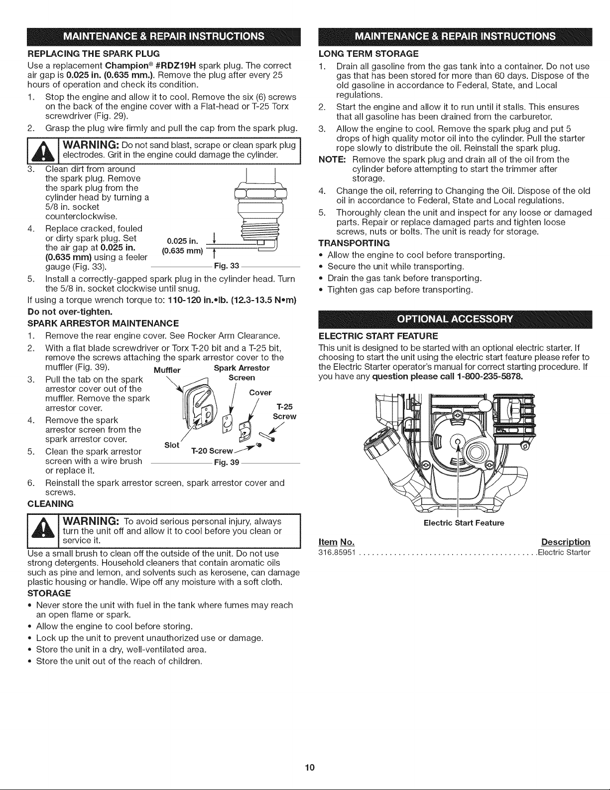
ELECTRIC START FEATURE
This unit is designed to be started with an optional electric starter. If
choosing to start the unit using the electric start feature please refer to
the Electric Starter operator's manual for correct starting procedure. If
you have any question please call 1-800-235-5878.
i
1
Item No. Description
316.85951 ......................................... Electric Starter
Electric Start Feature
10
 Loading...