

Craftsman 316.791700 Operator's Manual

Operator's Manual
M
4-Cycle
Electric Start Capable
WEEDWACKER ®TRIMMER
Model No. 316.791700
INCREDI.PULL TM
UNBELIEVABLE STARTING E A S E
* SAFETY
* ASSEMBLY
* OPERATION
* MAINTENANCE
* PARTS LIST
* ESPANOL, R 13
CAUTION: Before using this
product, read this manual and
follow all safety rules and
operating instructions.
Sears Brands Management Corporation, Hoffman Estates, IL 60179 U.S.A.
Visit our website: www.craftsman.com
769=06806 P00 03/11
TABLEOFCONTENTS
RulesforSafeOperation....................................... 2
Warranty.................................................... 4
KnowYourUnit............................................... 4
AssemblyInstructions.......................................... 5
OilandFuelInformation........................................ 6
Starting/StoppingInstructions................................... 7
OperatingInstructions......................................... 8
MaintenanceandRepairInstructions.............................. 8
CleaningandStorage......................................... 10
OptionalAccessory........................................... 10
TroubleshootingChart........................................ 11
Specifications............................................... 12
PartsList................................................... 30
ServiceNumbers..................................... BackCover
Allinformation,illustrations,andspecificationsinthismanualarebasedonthe
latestproductinformationavailableatthetimeofprinting.Wereservetheright
tomakechangesatanytimewithoutnotice.
SPARKARRESTOR NOTE
NOTE: For users on U.S. Forest Land and in the states of California, Maine,
Oregon and Washington. All U.S. Forest Land and the state of California (Public
Resources Codes 4442 and 4443), Oregon and Washington require, by law that
certain internal combustion engines operated on forest brush and/or grass-covered
areas be equipped with a spark arrestor, maintained in effective working order, or
the engine be constructed, equipped and maintained for the prevention of fire.
Check with your state or local authorities for regulations pertaining to these
requirements. Failure to follow these requirements could subject you to liability or
a fine. This unit is factory equipped with a spark arrestor. If it requires
replacement, ask your LOCAL SERVICE DEALER to install the Accessory Part
#753=05245 Muffler Assembly.
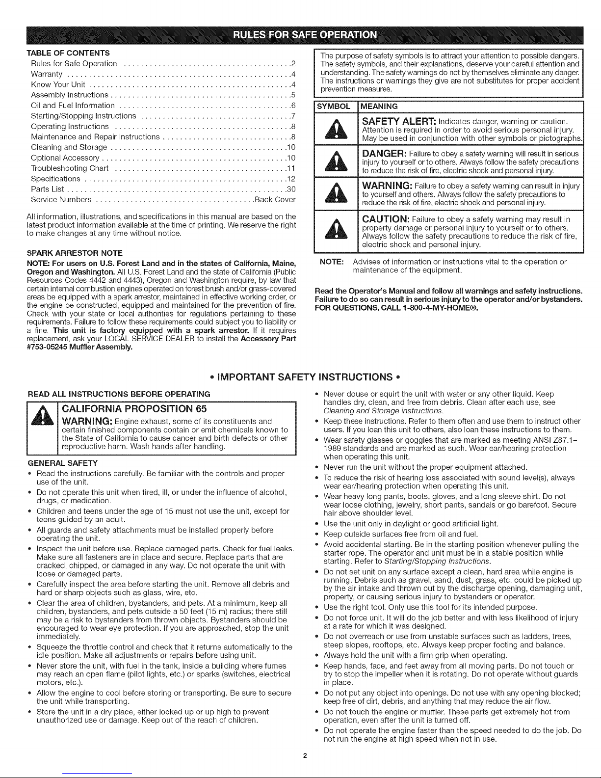
The purpose of safety symbols is to attract your attention to possible dangers.
The safety symbols, and their explanations, deserve your careful attention and
understanding. The safety warnings do not by themselves eliminate any danger.
The instructions or warnings they give are not substitutes for proper accident
prevention measures.
SYMBOL MEANING
41_ SAFETY ALERT: Indicates danger, warning or caution.
Attention is required in order to avoid serious personal injury.
May be used in conjunction with other symbols or pictographs.
injury to yourself or to others. Always follow the safety precautions
DANGER: Failure to obey a safety warning will result in serious
to reduce the risk of fire, electric shock and personal injury.
WARNING: Failure to obey a safety warning can result in injuryto yourself and others. Always follow the safety precautions to
reduce the risk of fire, electric shock and personal injury.
AI_ CAUTION: Failure to obey a safety warning may result in
NOTE: Advises of information or instructions vital to the operation or
Read the Operator's Manual and follow all warnings and safety instructions.
Failure to do so can result in serious injury to the operator and/or bystanders.
FOR QUESTIONS, CALL 1=800=4=MY=HOME®.
property damage or personal injury to yourself or to others.
Always follow the safety precautions to reduce the risk of fire,
electric shock and personal injury.
maintenance of the equipment.
• IMPORTANT SAFETY INSTRUCTIONS
READ ALL INSTRUCTIONS BEFORE OPERATING
WARNING: Engine exhaust, some of its constituents and
certain finished components contain or emit chemicals known to
_ CALIFORNIA PROPOSiTiON 65
GENERAL SAFETY
• Read the instructions carefully. Be familiar with the controls and proper
• Do not operate this unit when tired, ill, or under the influence of alcohol,
• Children and teens under the age of 15 must not use the unit, except for
• All guards and safety attachments must be installed properly before
• Inspect the unit before use. Replace damaged parts. Check for fuel leaks.
the State of California to cause cancer and birth defects or other
reproductive harm. Wash hands after handling.
use of the unit.
drugs, or medication.
teens guided by an adult.
operating the unit.
Make sure all fasteners are in place and secure. Replace parts that are
cracked, chipped, or damaged in any way. Do not operate the unit with
loose or damaged parts.
Carefully inspect the area before starting the unit. Remove all debris and
hard or sharp objects such as glass, wire, etc.
Clear the area of children, bystanders, and pets. At a minimum, keep all
children, bystanders, and pets outside a 50 feet (15 m) radius; there still
may be a risk to bystanders from thrown objects. Bystanders should be
encouraged to wear eye protection. If you are approached, stop the unit
immediately.
Squeeze the throttle control and check that it returns automatically to the
idle position. Make all adjustments or repairs before using unit.
Never store the unit, with fuel in the tank, inside a building where fumes
may reach an open flame (pilot lights, etc.) or sparks (switches, electrical
motors, etc.).
Allow the engine to cool before storing or transporting. Be sure to secure
the unit while transporting.
Store the unit in a dry place, either locked up or up high to prevent
unauthorized use or damage. Keep out of the reach of children.
Never douse or squirt the unit with water or any other liquid. Keep
handles dry, clean, and free from debris. Clean after each use, see
Cleaning and Storage instructions.
Keep these instructions. Refer to them often and use them to instruct other
users. If you loan this unit to others, also loan these instructions to them.
Wear safety glasses or goggles that are marked as meeting ANSI Z87.1-
1989 standards and are marked as such. Wear ear/hearing protection
when operating this unit.
Never run the unit without the proper equipment attached.
To reduce the risk of hearing loss associated with sound level(s), always
wear ear/hearing protection when operating this unit.
Wear heavy long pants, boots, gloves, and a long sleeve shirt. Do not
wear loose clothing, jewelry, short pants, sandals or go barefoot. Secure
hair above shoulder level.
Use the unit only in daylight or good artificial light.
Keep outside surfaces free from oil and fuel.
Avoid accidental starting. Be in the starting position whenever pulling the
starter rope. The operator and unit must be in a stable position while
starting. Refer to Starting/Stopping Instructions.
Do not set unit on any surface except a clean, hard area while engine is
running. Debris such as gravel, sand, dust, grass, etc. could be picked up
by the air intake and thrown out by the discharge opening, damaging unit,
property, or causing serious injury to bystanders or operator.
Use the right tool. Only use this tool for its intended purpose.
Do not force unit. It will do the job better and with less likelihood of injury
at a rate for which it was designed.
Do not overreach or use from unstable surfaces such as ladders, trees,
steep slopes, rooftops, etc. Always keep proper footing and balance.
Always hold the unit with a firm grip when operating.
Keep hands, face, and feet away from all moving parts. Do not touch or
try to stop the impeller when it is rotating. Do not operate without guards
in place.
Do not put any object into openings. Do not use with any opening blocked;
keep free of dirt, debris, and anything that may reduce the air flow.
Do not touch the engine or muffler. These parts get extremely hot from
operation, even after the unit is turned off.
Do not operate the engine faster than the speed needed to do the job. Do
not run the engine at high speed when not in use.

,, Always stop the engine when operation is delayed or when walking from
one location to another.
,, Use only genuine factory replacement parts and accessories for this Emit.
These are available from your authorized service dealer. Use of any
unauthorized parts or accessories could lead to serious injury to the user
or damage to the unit. and void your warranty.
• If you strike or come into contact with a foreign object, stop the engine
immediately and check for damage. Do not operate before repairing
damage. Do not operate the unit with loose or damaged parts.
,, To reduce fire hazard, replace faulty muffler and spark arrestor. Keep the
engH_e and muffler free from grass, leaves, excesswe grease or carbon
build up.
OiL AND FUEL SAFETY
m
_ WARNING: Gasohne is highly flammable and its vapors can
,, Store fuel only in contan_ers specifically des@_ed and approved for the
,, Always stop the engine and allow it to cool before fllhng the tank. Never
,, Always add fuel in a clean, well-ventilated outdoor area where there are no
explode if ignited. Take the following precautions:
storage of such materials.
remove the fuel tank cap or add fuel when the engHqe is hot. Always
loosen the fuel tank cap slowly to reheve any pressure in the tank before
fuehng. DO NOT smoke.
sparks or flames. DO NOT smoke.
,, Never operate the unit without the fuel cap securely in place.
,, Avoid creating a source of ignition for spilled fuel. Wipe up any spilled fuel
from the unit immediately, before starting the unit. Move the unit at least
30 ft. (9.1 m) from the fuehng source and site before starting the engine.
DO NOT smoke.
,, Never start or run the unit inside a closed room or building. Breathing exhaust
fumes can kill. Operate this unit only in a well ventilated outdoor area.
TRIMMER SAFETY
,, The trimmer attachment shield must always be in place while operating
the unit. Do not operate unit without both tnmmHqg hnes extended, and
the proper hne installed. Do not extend the trimming hne beyond the
length of the shield.
,, Adjust the D-handle that provides the best possible grip.
,, Be sure the trimmer attachment is not in contact with anything before
starting the unit.
,, Use only 0.095 in. (2.41 mm) replacement hne. Never use metal-reinforced
hne, wire, chain or rope. These can break off and become dangerous
projectiles.
,, Keep unit clean of vegetation and other materials. They may become
lodged between the trimmer attachment and shield.
,, Keep hands, face, and feet away from all moving parts. Do not touch or
try to stop the trimmer attachment when _trotates.
SAVE THESE INSTRUCTIONS
= SAFETY & INTERNATIONAL SYMBOLS •
This operator's manual describes safety and international symbols and plctographs that may appear on this product. Read the operator's manual for complete
safety, assembly, operating and maintenance and repair information.
SYMBOL
©
MEANING
, SAFETY ALERT SYMBOL
Indicates danger, warning or cautuon. May be used an
conjunctuon wuth other symbols or p_ctographs.
,, READ OPERATOR'S MANUAL
WARNING: Read the operator's manual(s) and follow all
warnings and safety nstruchons. Failure to do so can result
unsenous ,njury to the operator and/or bystanders.
" WEAR EYE AND HEARING PROTECTION
WARNING: Thrown objects and loud nousecan cause
severe eye unjuryand heanng loss. Wear eye protection
meehng ANSi Z87.1-1989 standards and ear protection when
operatung th_s unit. Use a full face shueld when needed.
UNLEADED FUEL
Always use clean, fresh unleaded fuel
, OIL
Refer to operator's manual for the proper type of oul.
• DO NOT USE E85 FUEL iN THiS UNiT
WARNING: It has been proven that fuel containing
greater than 10% ethanol wal hkely damage this engine and
voud the warranty.
SYMBOL
|
O"
MEANING
ON/OFF STOP CONTROL
ON / START / RUN
ON/OFF STOP CONTROL
OFF or STOP
PRIMER BULB
Push primer bulb, fully and slowly, 10 hmes.
THROWN OBJECTS AND ROTATING CUTTER CAN
CAUSE SEVERE _NJURY
WARNING: Small objects can be propelled at h,gh
speed, caus,ng Injury. Keep away from the rotating rotor.
KEEP BYSTANDERS AWAY
WARNING: Keep all bystanders, espec,ally children and
pets, at least 50 feet (15 m.) from the operahng area.
HOT SURFACE
WARNING: Do not touch a hot engine. These parts get
extremely hot from operation and may cause severe burns.
When the unit _sturned off the engine w,II remain hot for a
short hme.
SHARP BLADE
WARNING: Sharp blade on trimmer attachment shield To
prevent senous =njury,do not touch the hne cutting blade
CRAFTSMAN2YEAR FULL WARRANTY
FOR 2 YEARS from the date of purchase, this product is warranted against any defects in material or workmanship. Defective product will receive free repair or
free replacement if repair is unavailable.
For warranty coverage details to obtain repair or replacement, visit the web site: www.craftsman.com
This warranty covers ONLY defects in material and workmanship. Warranty coverage does NOT include:
• Expendable items that can wear out from normal use within the warranty period, such as cutting line, air cleaner, or spark plug.
Product damage resulting from user attempts at product modification or repair or caused by product accessories.
Repairs necessary because of accident or failure to operate or maintain the product according to all supplied instructions.
Preventive maintenance, or repairs necessary due to improper fuel mixture, contaminated or stale fuel.
This warranty is void if this product is ever used while providing commercial services or if rented to another person. This warranty gives you specific legal
rights, and you may also have other rights which vary from state to state.
Sears Brands Management Corporation, Hoffman Estates, IL 60179
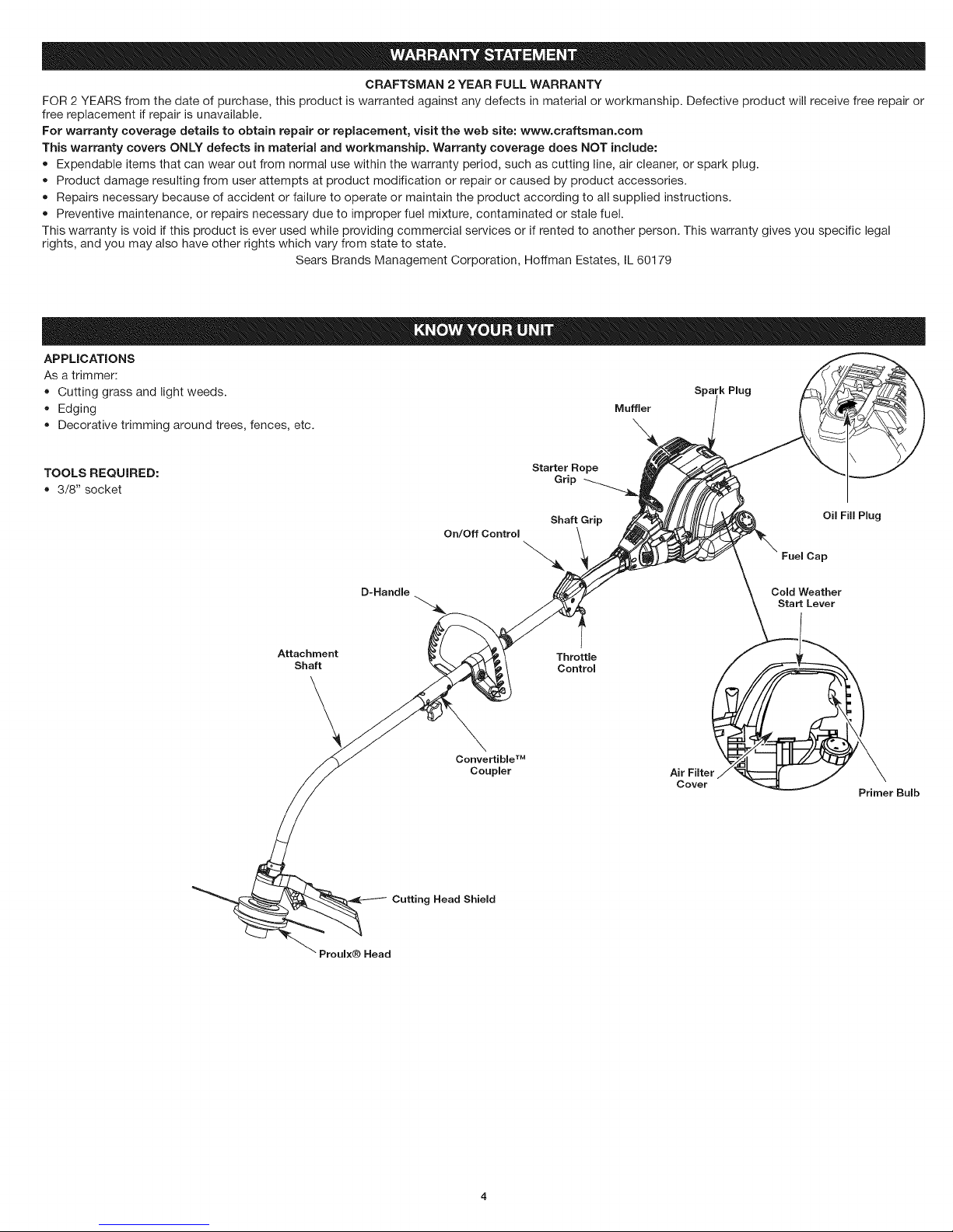
APPLICATIONS
As a trimmer:
Cutting grass and light weeds.
Edging
Decorative trimming around trees, fences, etc.
Muffler
\
Spa 'k Plug
TOOLS REQUIRED:
• 3/8" socket
Starter Rope
On/Off Control \ ,_
Atta;hhment _, _. z_ _ \ ThorOtt_lo_
Convertible TM
_ Coupler
Air Filter
Cover
Oil Fill Plug
Fuel Cap
Cold Weather
Start Lever
Primer Bulb
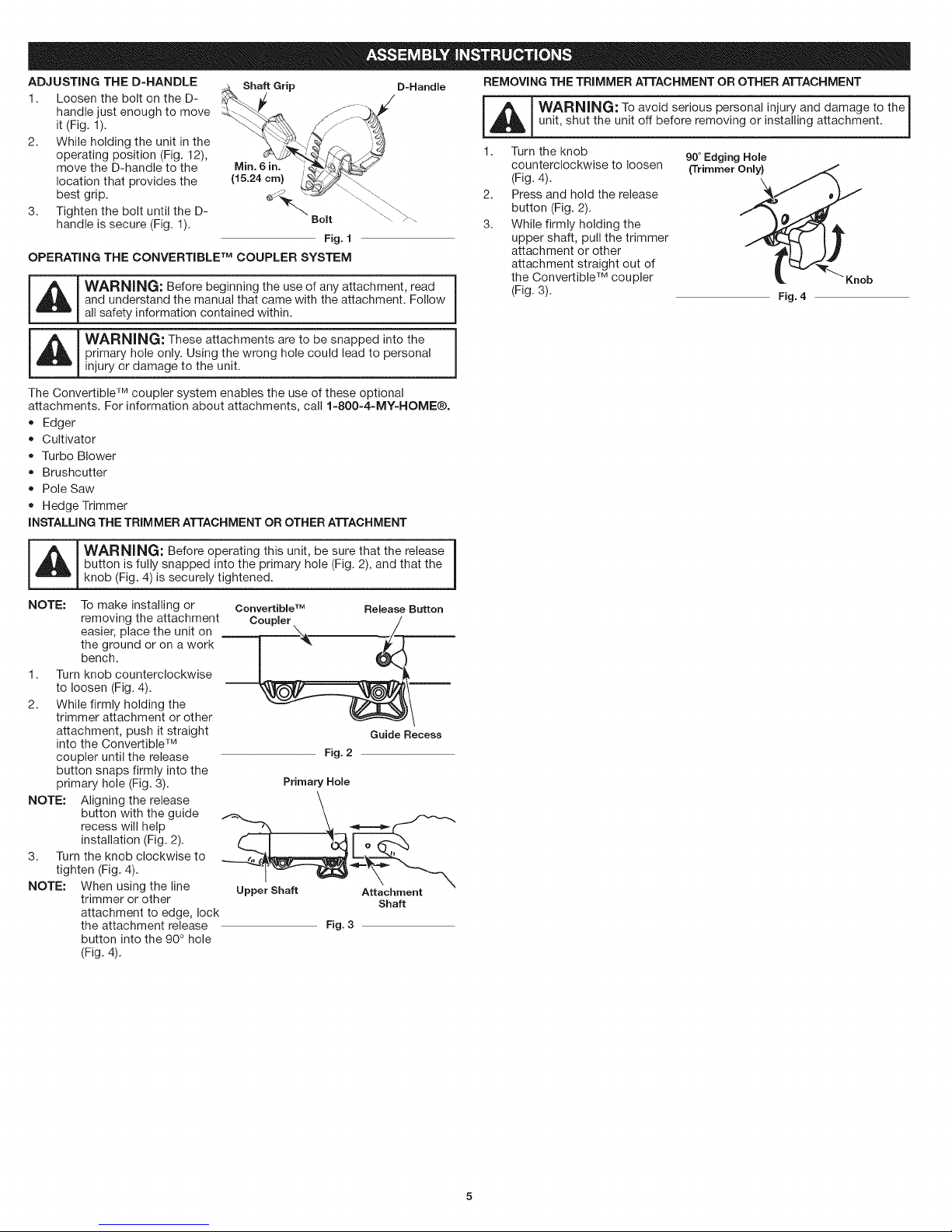
ADJUSTING THE D-HANDLE _._, Shaft Grip D-Handle REMOVING THE TRIMMER ATTACHMENT OR OTHER ATTACHMENT
1. Loosen the bolt on theD- _ j . _//
it (Fig. 1). unit, shut the unit off before removing or installing attachment.
2. While holding the unit in the
operating position (Fig. 12), 90°Edging Hole
handle just enough to move _ _L_ WARNING" T° av°id seri°us pers°nal injury and damage t° the i
move the D-handle to the (Trimmer Only}
bestl°cati°ngrip.thatprovides the ' _-_._'.,_. ---.__\\ 2. X4
3. Tighten the bolt until the D- "_ Bolt \"\ >....
handle is secure (Fig. 1). 3.
OPERATING THE CONVERTIBLE TM COUPLER SYSTEM
_ ARNING: Before beginning the use of any attachment, read
and understand the manual that came with the attachment. Follow
all safety information contained within.
Fig. 1
1. Turn the knob
counterclockwise to loosen
(Fig. 4).
Press and hold the release
button (Fig. 2).
While firmly holding the
upper shaft, pull the trimmer
attachment or other
attachment straight out of
the Convertible TM coupler
(Fig. 3).
Fig. 4
Knob
_ ARNING: These attachments are to be snapped into the
The Convertible TM coupler system enables the use of these optional
attachments. For information about attachments, call 1-800-4-MY-HOME®.
• Edger
INSTALLING THE TRIMMER ATTACHMENT OR OTHER ATTACHMENT
_WARNING: Before operating this unit, be sure that the release |
NOTE: To make installing or
1. Turn knob counterclockwise
2. While firmly holding the
NOTE: Aligning the release
3. Turn the knob clockwise to
NOTE: When using the line
primary hole only. Using the wrong hole could lead to personal
injury or damage to the unit.
Cultivator
Turbo Blower
Brushcutter
Pole Saw
Hedge Trimmer
button is fully snapped into the primary hole (Fig. 2), and that the
knob (Fig. 4) is securely tightened.
removing the attachment
easier, place the unit on
the ground or on a work
bench.
to loosen (Fig. 4).
trimmer attachment or other
attachment, push it straight
into the Convertible TM
coupler until the release
button snaps firmly into the
primary hole (Fig. 3).
button with the guide
recess will help
installation (Fig. 2).
tighten (Fig. 4).
trimmer or other
attachment to edge, lock
the attachment release
button into the 90 ° hole
(Fig. 4).
Convertible TM Release Button
Coupler /
Fig.2
Primary Hole
,
Upper Shaft Attachment
Fig. 3
Guide Recess
Shaft
|
_IL I WARNING: OVERFILLING OIL CRANKCASE MAY CAUSE
SERIOUS PERSONAL INJURY. Check and maintain the proper oil
I _overemphasized. Check the oil before each use and change it as
_ needed. See Changing the Oil.
RECOMMENDED OIL TYPE
Using the proper type and weight of oil in the crankcase is extremely important.
Check the oil before each use and change the oil regularly. Failure to use the
correct oil, or using dirty oil, can cause premature engine wear and failure.
Use a high-quality SAE 30 weight oil of API (American Petroleum Institute)
service class SF,SG, SH.
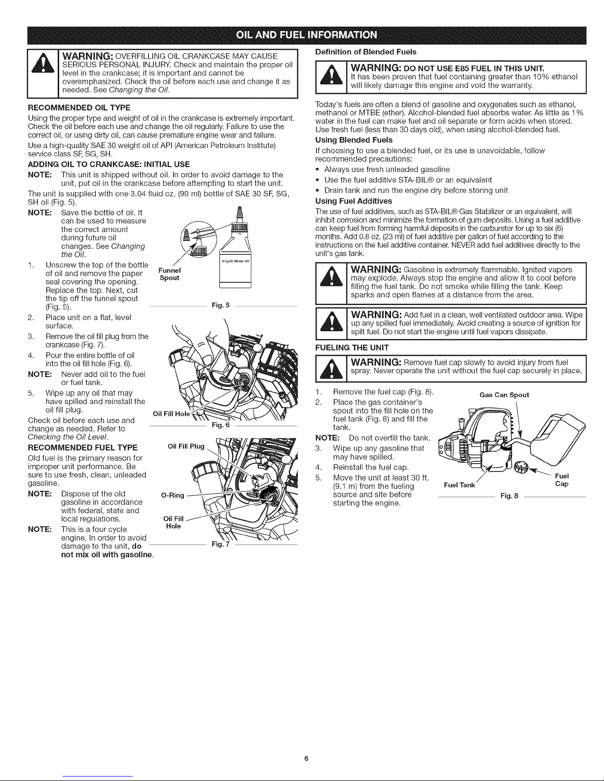
ADDING OIL TO CRANKCASE: INITIAL USE
NOTE: This unit is shipped without oil. In order to avoid damage to the
The unit is supplied with one 3.04 fluid oz. (90 ml) bottle of SAE 30 SF, SG,
SH oil (Fig. 5).
NOTE: Save the bottle of oil. It
1. Unscrew the top of the bottle _.c_,....... ,
2. Place unit on a flat, level
3. Remove the oil fill plug from the
4. Pour the entire bottle of oil
NOTE: Never add oil to the fuel
5. Wipe up any oil that may
Check oil before each use and
change as needed. Refer to Fig.6
Checking the Oil Level.
RECOMMENDED FUEL TYPE oil FillPlug
Old fuel is the primary reason for
improper unit performance. Be
sure to use fresh, clean, unleaded
gasoline.
NOTE: Dispose of the old O-Ring
NOTE: This is a four cycle Hole
level in the crankcase; it is important and cannot be
unit, put oil in the crankcase before attempting to start the unit.
can be used to measure
the correct amount
during future oil
changes. See Changing
the Oil. -------
of oil and remove the paper Fun
seal covering the opening. Spout
Replace the top. Next, cut
the tip off the funnel spout
(Fig. 5). Fig.5
surface.
crankcase (Fig. 7).
into the oil fill hole (Fig. 6).
or fuel tank.
have spilled and reinstall the
oil fill plug. oil Fill Hole'
gasoline in accordance
with federal, state and
local regulations. Oil Fill
engine. In order to avoid
damage to the unit, do Fig. 7
not mix oil with gasoline.
Definition of Blended Fuels
_ ARNING: DO NOT USE E85 FUEL IN THIS UNIT.
Today's fuels are often a blend of gasoline and oxygenates such as ethanol,
methanol or MTBE (ether). Alcohol-blended fuel absorbs water. As little as 1%
water in the fuel can make fuel and oil separate or form acids when stored.
Use fresh fuel (less than 30 days old), when using alcohol-blended fuel.
Using Blended Fuels
If choosing to use a blended fuel, or its use is unavoidable, follow
recommended precautions:
• Always use fresh unleaded gasoline
• Use the fuel additive STA-BIL® or an equivalent
• Drain tank and run the engine dry before storing unit
Using Fuel Additives
The useof fuel additives, such as STA-BIL® Gas Stabilizer or an equivalent, will
inhibit corrosion and minimize the formation of gum deposits. Using a fuel additive
can keep fuel from forming harmful deposits in the carburetor for up to six (6)
months. Add 0.8 oz. (23 ml) of fuel additive per gallon of fuel according to the
instructions on the fuel additive container. NEVER add fuel additives directly to the
unit's gas tank.
It has been proven that fuel containing greater than 10% ethanol
will likely damage this engine and void the warranty.
WARNING: Gasoline is extremely flammable. Ignited vapors
may explode. Always stop the engine and allow it to cool before
filling the fuel tank. Do not smoke while filling the tank. Keep
sparks and open flames at a distance from the area.
WARNING: Add fuel in a clean, well ventilated outdoor area. Wipe
i _ up any spilled fuel immediately. Avoid creating a source of ignition for
i
i
FUELING THE UNiT
-- i_ WARNING: Remove fuel cap slowly to avoid injury from fuel
1. Remove the fuel cap (Fig. 8).
2. Place the gas container's
NOTE: Do not overfill the tank.
3. Wipe up any gasoline that
4. Reinstall the fuel cap.
5. Move the unit at least 30 ft.
spilt fuel. Do not start the engine until fuel vapors dissipate.
spray. Never operate the unit without the fuel cap securely in place.
Gas Can Spout
spout into the fill hole on the
fuel tank (Fig. 8) and fill the
tank.
may have spilled.
(9.1 m) from the fueling
source and site before
starting the engine.
Fuel Tank Cap
Fig. 8
Fuel
_ WARNI NG: Operate this unit only in a well-ventilated outdoor area.1
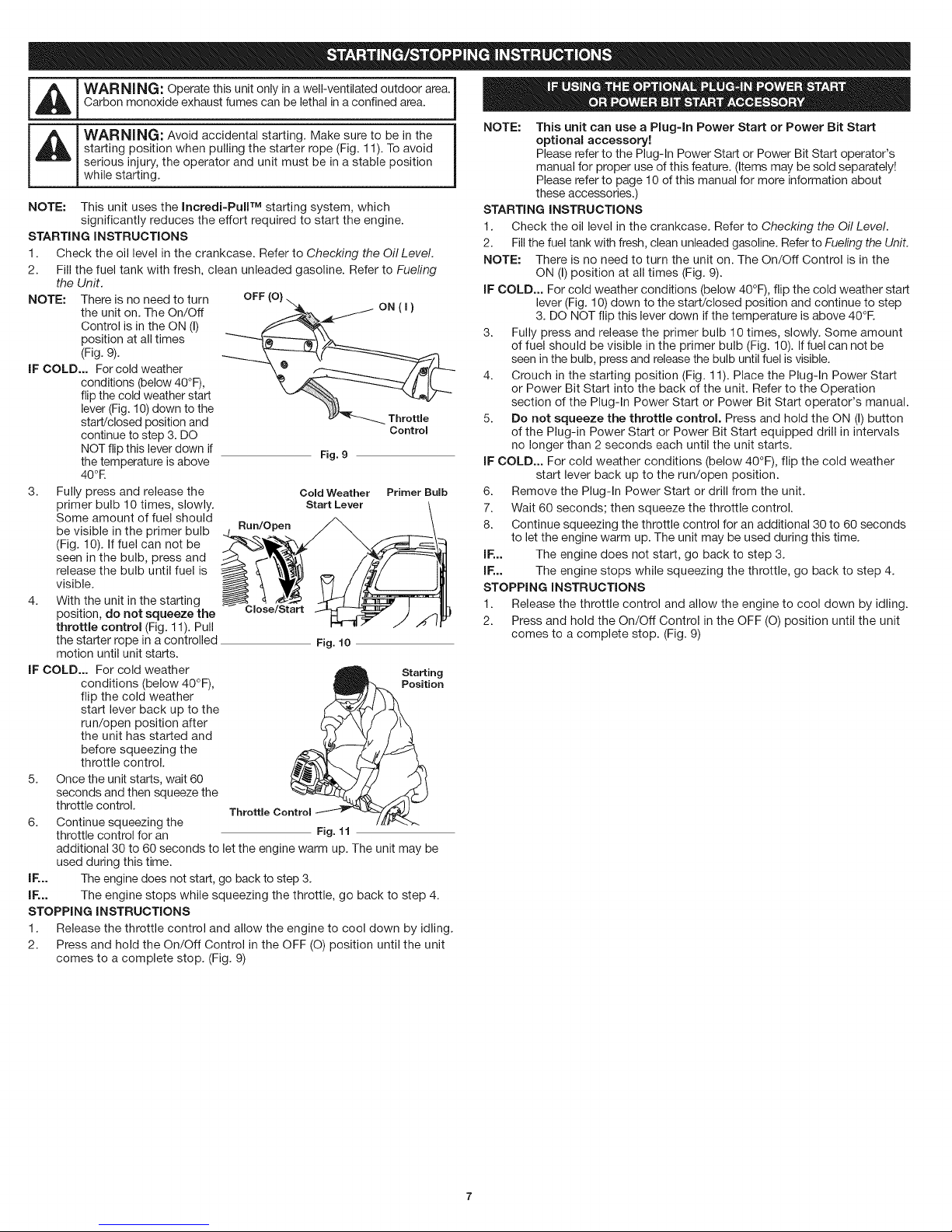
NOTE: This unit uses the Incredi-PuiF M starting system, which
STARTING INSTRUCTIONS
1. Check the oil level in the crankcase. Refer to Checking the Oil Level.
2. Fill the fuel tank with fresh, clean unleaded gasoline. Refer to Fueling
NOTE: There is no need to turn
IF COLD... For cold weather
3. Fully press and release the
4. With the unit in the starting
IF COLD... For cold weather
5. Once the unit starts, wait 60
6. Continue squeezing the
IF,.. The engine does not start, go back to step 3.
IF,.. The engine stops while squeezing the throttle, go back to step 4.
STOPPING INSTRUCTIONS
1. Release the throttle control and allow the engine to cool down by idling.
2. Press and hold the On/Off Control in the OFF (O) position until the unit
Carbon monoxide exhaust fumes can be lethal in a confined area. |
starting position when pulling the starter rope (Fig. 11). To avoid
serious injury, the operator and unit must be in a stable position
WARNING: Avoid accidental starting. Make sure to be in the
while starting.
significantly reduces the effort required to start the engine.
the Unit.
the unit on. The On/Off
Control is in the ON (I)
position at all times
(Fig. 9).
conditions (below 40°F),
flip the cold weather start
lever (Fig. 10)down to the
start/closed position and
continue to step 3. DO
NOT flip this lever down if
the temperature is above
40°R
primer bulb 10 times, slowly.
Some amount of fuel should
be visible in the primer bulb
(Fig. 10). If fuel can not be
seen in the bulb, press and
release the bulb until fuel is
visible.
position, do not squeeze the
throttle control (Fig. 11). Pull
the starter rope in a controlled
motion until unit starts.
conditions (below 40°F),
flip the cold weather
start lever back up to the
run/open position after
the unit has started and
before squeezing the
throttle control.
seconds and then squeeze the
throttle control.
throttle control for an
additional 30 to 60 seconds to let the engine warm up. The unit may be
used during this time.
comes to a complete stop. (Fig. 9)
Run/Open
Close/Start
Throttle Control _ _z/)#_
Fig. 9
Cold Weather Primer Bulb
Start Lever
Fig. 10
h Starti
Fig. 11
|
NOTE: This unit can use a Plug-In Power Start or Power Bit Start
i
STARTING INSTRUCTIONS
1. Check the oil level in the crankcase. Refer to Checking the Oil Level.
2. Fill the fuel tank with fresh, clean unleaded gasoline. Refer to Fueling the Unit.
NOTE: There is no need to turn the unit on. The On/Off Control is in the
IF COLD... For cold weather conditions (below 40°F), flip the cold weather start
3. Fully press and release the primer bulb 10 times, slowly. Some amount
4. Crouch in the starting position (Fig. 11). Place the Plug-In Power Start
5. Do not squeeze the throttle control. Press and hold the ON (I) button
IF COLD... For cold weather conditions (below 40°F), flip the cold weather
6. Remove the Plug-In Power Start or drill from the unit.
7. Wait 60 seconds; then squeeze the throttle control.
8. Continue squeezing the throttle control for an additional 30 to 60 seconds
IF,.. The engine does not start, go back to step 3.
IF,.. The engine stops while squeezing the throttle, go back to step 4.
STOPPING INSTRUCTIONS
1. Release the throttle control and allow the engine to cool down by idling.
2. Press and hold the On/Off Control in the OFF (O) position until the unit
optional accessory!
Please refer to the Plug-In Power Start or Power Bit Start operator's
manual for proper use of this feature. (Items may be sold separately!
Please refer to page 10 of this manual for more information about
these accessories.)
ON (I) position at all times (Fig. 9).
lever (Fig. 10) down to the start/closed position and continue to step
3. DO NOT flip this lever down if the temperature is above 40°R
of fuel should be visible in the primer bulb (Fig. 10). Iffuel can not be
seen in the bulb, press and release the bulb until fuel is visible.
or Power Bit Start into the back of the unit. Refer to the Operation
section of the Plug-In Power Start or Power Bit Start operator's manual.
of the Plug-in Power Start or Power Bit Start equipped drill in intervals
no longer than 2 seconds each until the unit starts.
start lever back up to the run/open position.
to let the engine warm up. The unit may be used during this time.
comes to a complete stop. (Fig. 9)
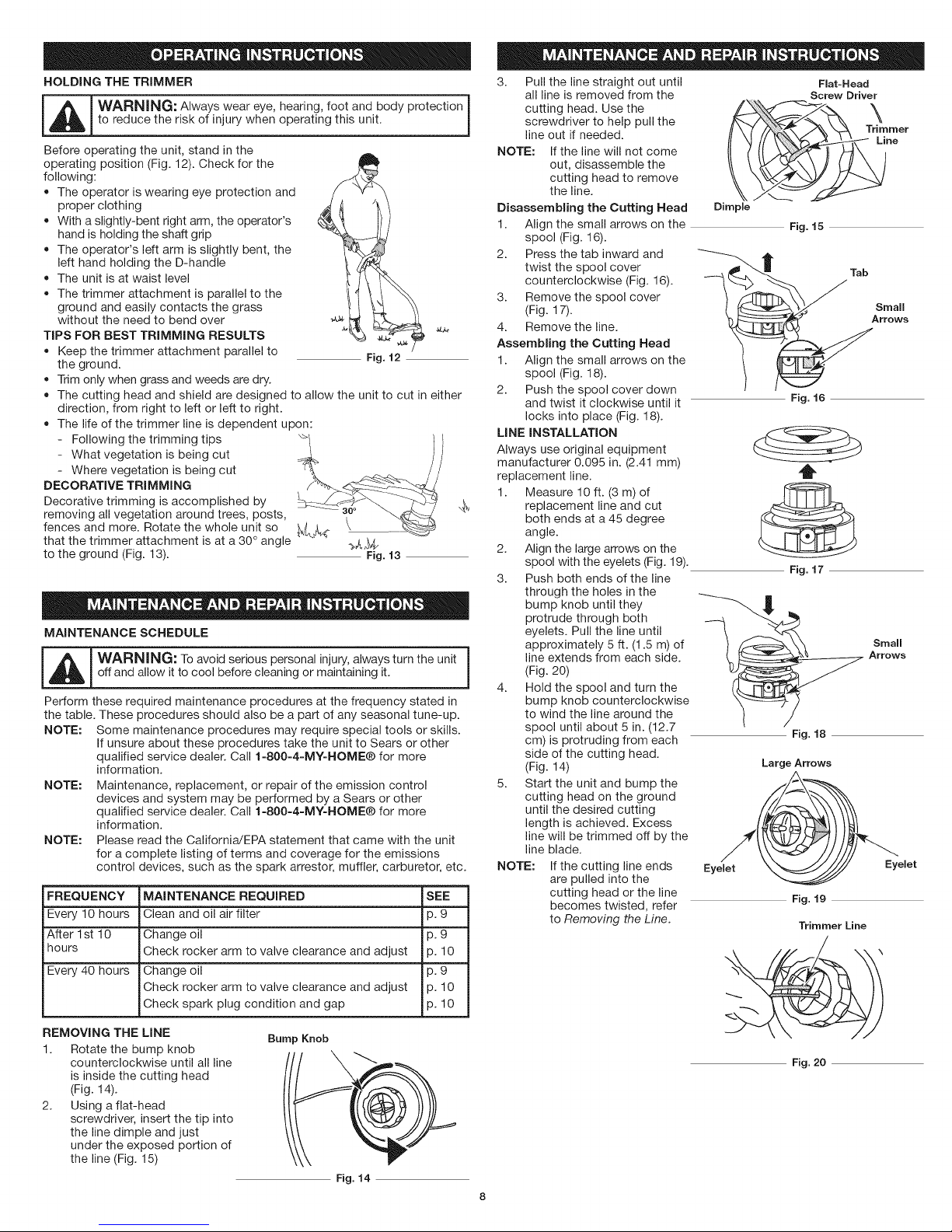
HOLDING THE TRIMMER
-- i_[_ ARNING: Always wear eye, hearing, foot and body protection
Before operating the unit, stand in the
operating position (Fig. 12). Check for the
following:
• The operator is wearing eye protection and
TIPS FOR BEST TRiMMiNG RESULTS
DECORATIVE TRIMMING
Decorative trimming is accomplished by
removing all vegetation around trees, posts,
fences and more. Rotate the whole unit so
that the trimmer attachment is at a 30 ° angle _k _V,,
to the ground (Fig. 13). Fig. 13
MAINTENANCE SCHEDULE
_ WAR N ' N G == To avoid serious personal injury, always turn the unit 1
Perform these required maintenance procedures at the frequency stated in
the table. These procedures should also be a part of any seasonal tune-up.
NOTE: Some maintenance procedures may require special tools or skills.
NOTE:
NOTE:
FREQUENCY MAINTENANCE REQUIRED SEE
Every 10 hours Clean and oil air filter p. 9
After 1st 10 Change oil p. 9
hours Check rocker arm to valve clearance and adjust p. 10
Every 40 hours Change oil p. 9
to reduce the risk of injury when operating this unit.
proper clothing
With a slightly-bent right arm, the operator's
hand is holding the shaft grip
The operator's left arm is slightly bent, the
left hand holding the D-handle
The unit is at waist level
The trimmer attachment is parallel to the
ground and easily contacts the grass
without the need to bend over
Keep the trimmer attachment parallel to
the ground.
Trim only when grass and weeds are dry.
The cutting head and shield are designed to allow the unit to cut in either
direction, from right to left or left to right.
The life of the trimmer line is dependent upon:
Following the trimming tips i
What vegetation is being cut
Where vegetation is being cut
off and allow it to cool before cleaning or maintaining it.
If unsure about these procedures take the unit to Sears or other
qualified service dealer. Call 1=800=4=MY=HOME® for more
information.
Maintenance, replacement, or repair of the emission control
devices and system may be performed by a Sears or other
qualified service dealer. Call 1=800=4=MY-HOME® for more
information.
Please read the California!EPA statement that came with the unit
for a complete listing of terms and coverage for the emissions
control devices, such as the spark arrestor, muffler, carburetor, etc.
Check rocker arm to valve clearance and adjust p. 10
Check spark plug condition and gap p. 10
Fig. 12
3. Pull the line straight out until
all line is removed from the
cutting head. Use the
screwdriver to help pull the
line out if needed.
NOTE: If the line will not come
Disassembling the Cutting Head
1. Align the small arrows on the
2. Press the tab inward and
3. Remove the spool cover
4. Remove the line.
Assembling the Cutting Head
1. Align the small arrows on the
2. Push the spool cover down
LiNE iNSTALLATiON
Always use original equipment
manufacturer 0.095 in. (2.41 ram)
replacement line.
1. Measure 10 ft. (3 m) of
4_
2. Align the large arrows on the
3. Push both ends of the line
4. Hold the spool and turn the
5. Start the unit and bump the
NOTE: If the cutting line ends
out, disassemble the
cutting head to remove
the line.
spool (Fig. 16).
twist the spool cover
counterclockwise (Fig. 16).
(Fig. 17).
spool (Fig. 18).
and twist it clockwise until it
locks into place (Fig. 18).
replacement line and cut
both ends at a 45 degree
angle.
spool with the eyelets (Fig. 19).
through the holes in the
bump knob until they
protrude through both
eyelets. Pull the line until
approximately 5 ft. (1.5 m) of
line extends from each side.
(Fig. 20)
bump knob counterclockwise
to wind the line around the
spool until about 5 in. (12.7
cm) is protruding from each
side of the cutting head.
(Fig. 14)
cutting head on the ground
until the desired cutting
length is achieved. Excess
line will be trimmed off by the
line blade.
are pulled into the
cutting head or the line
becomes twisted, refer
to Removing the Line.
Flat-Head
Screw Driver
_ Tr_mmer
Dimple
Fig. 15
Fig. 16
t
Fig. 17
Arrows
Fig. 18
Large Arrows
Eyelet Eyelet
Fig. 19
Trimmer Line
REMOVING THE LiNE
1. Rotate the bump knob
counterclockwise until all line
is inside the cutting head
(Fig. 14).
2. Using a fiat-head
screwdriver, insert the tip into
the line dimple and just
under the exposed portion of
the line (Fig. 15)
Bump Knob
Fig. 20
Fig. 14
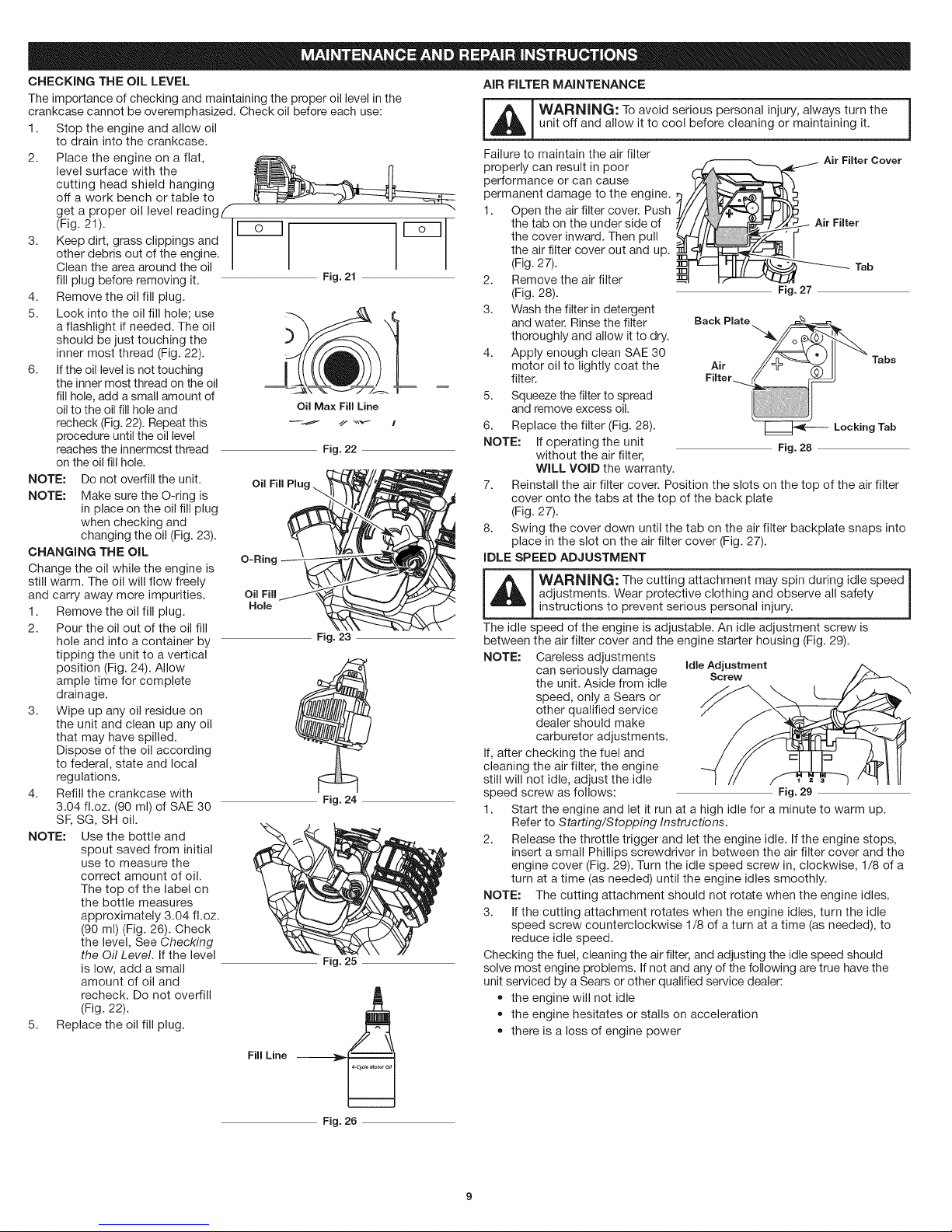
CHECKING THE OiL LEVEL
The importance of checking and maintaining the proper oil level in the
crankcase cannot be overemphasized. Check oil before each use:
1. Stop the engine and allow oil
to drain into the crankcase.
2. Place the engine on a flat,
level surface with the
cutting head shield hanging
off a work bench or table to
get a proper oil level reading (
(Fig. 21).
3. Keep dirt, grass clippings and
other debris out of the engine.
Clean the area around the oil
fill plug before removing it.
Fig. 21
4. Remove the oil fill plug.
5. Look into the oil fill hole; use
a flashlight if needed. The oil
should be just touching the
inner most thread (Fig. 22).
6. If the oil level is not touching
the inner most thread on the oil
fill hole, add a small amount of
oil to the oil fill hole and
Oil Max Fill Line
recheck (Fig.22). Repeat this
procedure until the oil level
reaches the innermost thread
Fig. 22
on the oil fill hole.
NOTE: Do not overfill the unit.
NOTE: Make sure the O-ring is
Oil Fill Plug.
in place on the oil fill plug
when checking and
changing the oil (Fig. 23).
CHANGING THE OIL
Change the oil while the engine is
still warm. The oil will flow freely
and carry away more impurities.
1. Remove the oil fill plug.
2. Pour the oil out of the oil fill
hole and into a container by
O-Ring
Oil FilJ
Hole
Fig. 23
tipping the unit to a vertical
position (Fig. 24). Allow
ample time for complete
drainage.
3. Wipe up any oil residue on
the unit and clean up any oil
that may have spilled.
Dispose of the oil according
to federal, state and local
regulations.
4. Refill the crankcase with
3.04 fl.oz. (90 ml) of SAE 30
SF, SG, SH oil.
Fig. 24
NOTE: Use the bottle and
spout saved from initial
use to measure the
correct amount of oil.
The top of the label on
the bottle measures
approximately 3.04 fl.oz.
(90 ml) (Fig. 26). Check
the level, See Checking
the Qil Level. If the level
is low, add a small
Fig. 25
amount of oil and
recheck. Do not overfill
(Fig. 22).
5. Replace the oil fill plug.
Fill Line
AiR FILTER MAINTENANCE
_L_ ARNING: To avoid serious personal injury, always turn the
Failure to maintain the air filter
properly can result in poor
unit off and allow it to cool before cleaning or maintaining it.
Air FimterCover
performance or can cause
permanent damage to the engine.
1. Open the air filter cover. Push
the tab on the under side of Air Fimter
the cover inward. Then pull
the air filter cover out and up.
(Fig. 27). Tab
2. Remove the air filter
(Fig. 28). Fig. 27
3. Wash the filter in detergent
and water. Rinse the filter
Back Plate
thoroughly and allow it to dry.
4. Apply enough clean SAE 30
motor oil to lightly coat the Air
filter. Filter
5. Squeeze the filter to spread
and remove excess oil.
6. Replace the filter (Fig. 28).
NOTE: If operating the unit
without the air filter,
-- Locking Tab
Fig. 28
Tabs
WiLL VOID the warranty.
7. Reinstall the air filter cover. Position the slots on the top of the air filter
cover onto the tabs at the top of the back plate
(Fig. 27).
8. Swing the cover down until the tab on the air filter backplate snaps into
place in the slot on the air filter cover (Fig. 27).
IDLE SPEED ADJUSTMENT
_ ARNING: The cutting attachment may spin during idle speed
adjustments. Wear protective clothing and observe all safety
instructions to prevent serious personal injury.
The idle speed of the engine is adjustable. An idle adjustment screw is
between the air filter cover and the engine starter housing (Fig. 29).
NOTE: Careless adjustments
can seriously damage Idle Adjustment
the unit. Aside from idle
Screw
speed, only a Sears or
other qualified service
dealer should make
carburetor adjustments.
If, after checking the fuel and
cleaning the air filter, the engine
still will not idle, adjust the idle
speed screw as follows: Fig. 29
1. Start the engine and let it run at a high idle for a minute to warm up.
Refer to Starting/Stopping Instructions.
2. Release the throttle trigger and let the engine idle. If the engine stops,
insert a small Phillips screwdriver in between the air filter cover and the
engine cover (Fig. 29). Turn the idle speed screw in, clockwise, 1/8 of a
turn at a time (as needed) until the engine idles smoothly.
NOTE: The cutting attachment should not rotate when the engine idles.
3. If the cutting attachment rotates when the engine idles, turn the idle
speed screw counterclockwise 1/8 of a turn at a time (as needed), to
reduce idle speed.
Checking the fuel, cleaning the air filter, and adjusting the idle speed should
solve most engine problems. If not and any of the following are true have the
unit serviced by a Sears or other qualified service dealer:
• the engine will not idle
the engine hesitates or stalls on acceleration
there is a loss of engine power
Fig. 26
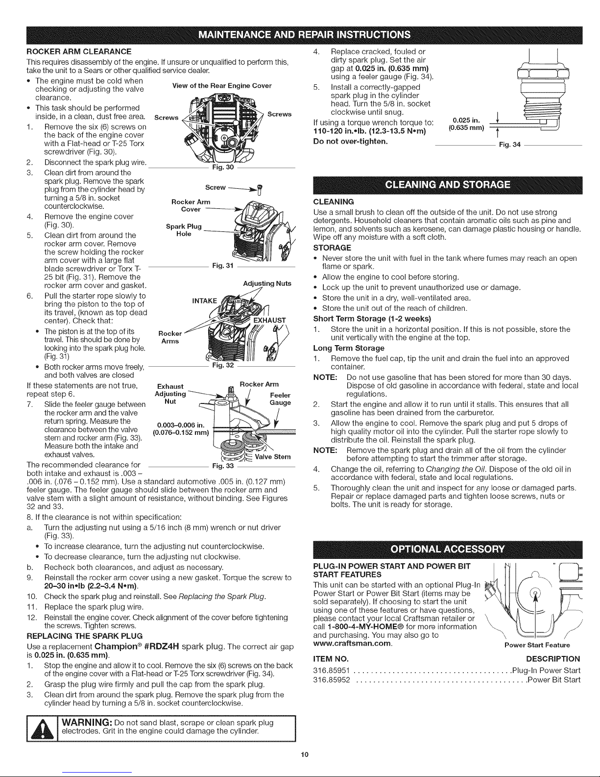
ROCKER ARM CLEARANCE
This requires disassembly of the engine. If unsure or unqualified to perform this,
take the unit to a Sears or other qualified service dealer.
• The engine must be cold when
checking or adjusting the valve
clearance.
This task should be performed
inside, in a clean, dust free area. Screws
1. Remove the six (6) screws on
the back of the engine cover
with a Flat-head or T-25 Torx
screwdriver (Fig. 30).
2. Disconnect the spark plug wire.
3. Clean dirt from around the
spark plug. Remove the spark
plug from the cylinder head by
turning a 5/8 in. socket
counterclockwise.
4. Remove the engine cover
(Fig. 30).
5. Clean dirt from around the
rocker arm cover. Remove
the screw holding the rocker
arm cover with a large flat
blade screwdriver or Torx T-
25 bit (Fig. 31). Remove the
rocker arm cover and gasket.
6. Pull the starter rope slowly to
bring the piston to the top of
its travel, (known as top dead
center). Check that:
The piston is at the top of its
travel. This should be done by Arms
looking into the spark plug hole.
(Fig.31)
Both rocker arms move freely,
and both valves are closed
If these statements are not true,
repeat step 6.
7. Slide the feeler gauge between
the rocker arm and the valve
return spring. Measure the
clearance between the valve
stem and rocker arm (Fig. 33).
Measure both the intake and
exhaust valves.
The recommended clearance for
both intake and exhaust is .003 -
.006 in. (.076 -0.152 mm). Use a standard automotive .005 in. (0.127 mm)
feeler gauge. The feeler gauge should slide between the rocker arm and
valve stem with a slight amount of resistance, without binding. See Figures
32 and 33.
8. If the clearance is not within specification:
a. Turn the adjusting nut using a 5/16 inch (8 mm) wrench or nut driver
(Fig. 33).
To increase clearance, turn the adjusting nut counterclockwise.
To decrease clearance, turn the adjusting nut clockwise.
b. Recheck both clearances, and adjust as necessary.
9. Reinstall the rocker arm cover using a new gasket. Torque the screw to
20-30 in,,Ib (2.2--3.4 N_ra).
10. Check the spark plug and reinstall. See Replacing the Spark Plug.
11. Replace the spark plug wire.
12. Reinstall the engine cover. Check alignment of the cover before tightening
the screws. Tighten screws.
REPLACING THE SPARK PLUG
is 0.025 in. (0.635 rata).
1. Stop the engine and allow it to cool. Remove the six (6)screws on the back
of the engine cover with a Flat-head or T-25 Torx screwdriver (Fig. 34).
2. Grasp the plug wire firmly and pull the cap from the spark plug.
3. Clean dirt from around the spark plug. Remove the spark plug from the
cylinder head by turning a 5/8 in. socket counterclockwise.
Champion #RDZ4H spark plug. The correct air gapUse a replacement ®
View of the Rear Engine Cover
Fig. 30
Spark Plug
HoNe
Fig. 31
mNTAKE
Nut _Gaugej
0.003-0,006 in..[_._,_,_,_,_,_,_,_,_,_ V
(0.076-0.152 ram)
Fig. 33
VaNveStem
Screws
Nuts
4. Replace cracked, fouled or
dirty spark plug. Set the air
gap at 0.025 in. (0.635 rata)
using a feeler gauge (Fig. 34).
5. Install a correctly-gapped
spark plug in the cylinder
head. Turn the 5/8 in. socket
clockwise until snug.
If using a torque wrench torque to:
110-120 in.olb. (12.3-13.5 Nora)
Do not over-tighten.
CLEANING
Use a small brush to clean off the outside of the unit. Do not use strong
detergents. Household cleaners that contain aromatic oils such as pine and
lemon, and solvents such as kerosene, can damage plastic housing or handle.
Wipe off any moisture with a soft cloth.
STORAGE
Never store the unit with fuel in the tank where fumes may reach an open
flame or spark.
Allow the engine to cool before storing.
Lock up the unit to prevent unauthorized use or damage.
Store the unit in a dry, well-ventilated area.
Store the unit out of the reach of children.
Short Terra Storage (1-2 weeks)
1. Store the unit in a horizontal position. If this is not possible, store the
unit vertically with the engine at the top.
Long Terra Storage
1. Remove the fuel cap, tip the unit and drain the fuel into an approved
container.
NOTE: Do not use gasoline that has been stored for more than 30 days.
2. Start the engine and allow it to run until it stalls. This ensures that all
3. Allow the engine to cool. Remove the spark plug and put 5 drops of
NOTE: Remove the spark plug and drain all of the oil from the cylinder
4. Change the oil, referring to Changing the Off. Dispose of the old oil in
5. Thoroughly clean the unit and inspect for any loose or damaged parts.
PLUG=IN POWER START AND POWER BIT =
START FEATURES
This unit can be started with an optional Plug-In
Power Start or Power Bit Start (items may be
sold separately). If choosing to start the unit
using one of these features or have questions,
please contact your local Craftsman retailer or
call 1=800=4-MY=HOME® for more information \
and purchasing. You may also go to
www.craftsman.com. Power Start Feature
ITEM NO. DESCRiPTiON
316.85951 ..................................... Plug-In Power Start
316.85952 ........................................ Power Bit Start
Dispose of old gasoline in accordance with federal, state and local
regulations.
gasoline has been drained from the carburetor.
high quality motor oil into the cylinder. Pull the starter rope slowly to
distribute the oil. Reinstall the spark plug.
before attempting to start the trimmer after storage.
accordance with federal, state and local regulations.
Repair or replace damaged parts and tighten loose screws, nuts or
bolts. The unit is ready for storage.
0.025 in.
(0.635 ram) 1'
Fig. 34
m i_L_ ARNING: Do not sand blast, scrape or clean spark plug
electrodes. Grit in the engine could damage the cylinder.
lO
 Loading...