

Craftsman 316791081, 7275340 Owner’s Manual

Operator's Manual
M
2-Cycle
WEEDWACKER® GAS TRIMMER
Model No. 316.791081
UNgtLtEFAIILE S TARTtN_ £ A S E _
o SAFETY
ASSEMBLY
OPERATION
MAINTENANCE
PARTS LIST
ESPANOL, R 13
CAUTION: Before using this
product, read this manual
and follow all safety rules
and operating instructions.
Sears Brands Management Corporation, Hoffman Estates, IL 60179 U.S.A.
Visit our website: www.craftsrnan.corn
769-06126 P00 06/10
CALiFORNiA PROPOSiTiON 65 WARNING
THE ENGINE EXHAUST FROM THIS PRODUCT CONTAINS CHEMICALS
KNOWN TO THE STATE OF CALiFORNiA TO CAUSE CANCER, BIRTH
TABLE OF CONTENTS
Safety Rules ................................................. 2
Warranty .................................................... 3
Know Your Unit ............................................... 4
Assembly Instructions .......................................... 4
Oil and Fuel Information ........................................ 5
Starting/Stopping Instructions ................................... 6
Operating Instructions ......................................... 6
Maintenance and Repair Instructions .............................. 7
Cleaning and Storage .......................................... 9
Troubleshooting Chart ........................................ 10
Specifications ............................................... 11
Parts List ................................................... 30
Service Numbers ..................................... Back Cover
SPARK ARRESTOR NOTE
NOTE: For users on U.S. Forest Land and in the states of California, Maine,
Oregon and Washington. All U.S. Forest Land and the state of California
(Public Resources Codes 4442 and 4443), Oregon and Washington require, by
law that certain internal combustion engines operated on forest brush and/or
grass-covered areas be equipped with a spark arrestor, maintained in effective
working order, or the engine be constructed, equipped and maintained for the
prevention of fire. Check with your state or local authorities for regulations
pertaining to these requirements. Failure to follow these requirements could
subject you to liability or a fine. This unit is factory equipped with a spark
arrestor. If it requires replacement, ask your LOCAL SERVICE DEALER to install
the Accessory Part #753-06182 Muffler Assembly
DEFECTS OR OTHER REPRODUCTIVE HARM.
= IMPORTANT SAFETY INSTRUCTIONS •
READ ALL INSTRUCTIONS BEFORE OPERATING
followed. Please read these instructions before operating the unit
I_, IWARNING: When using the unit, all safety rules must be
• Read the instructions carefully. Be familiar with the controls and proper
in order to ensure the safety of the operator and any bystanders.
I
Please keep these instructions for later use.
use of the unit.
Do not operate this unit when tired, ill, or under the influence of alcohol,
drugs, or medication.
Children and teens under the age of 15 must not use the unit, except for
teens guided by an adult.
All guards and safety attachments must be installed properly before
operating the unit.
Inspect the unit before use. Replace damaged parts. Check for fuel leaks.
Make sure all fasteners are in place and secure. Replace parts that are
cracked, chipped, or damaged in any way. Do not operate the unit with
loose or damaged parts.
Carefully inspect the area before starting the unit. Remove all debris and
hard or sharp objects such as glass, wire, etc.
Be aware of the risk of injury to the head, hands and feet.
Clear the area of children, bystanders, and pets. At a minimum, keep all
children, bystanders, and pets outside a 50 feet (15 m) radius; there still may
be a risk to bystanders from thrown objects. Bystanders should be
encouraged to wear eye protection. If approached, stop the unit immediately.
Use only 0.095 inch (2.41 mm) diameter original equipment manufacturer
replacement line. Never use metal-reinforced line, wire or rope. These can
break off and become dangerous projectiles.
Squeeze the throttle control and check that it returns automatically to the
idle position. Make all adjustments or repairs before using unit.
The purpose of safety symbols is to attract your attention to possible I
dangers. The safety symbols, and their explanations, deserve your careful
attention and understanding. The safety warnings do not by themselves
eliminate any danger. The instructions or warnings they give are not_
substitutes for proper accident prevention measures. J
SYMBOL MEANING
,_ SAFETY ALERT: Indicates danger, warning or caution.
Attention is required in order to avoid serious personal injury. May
be used in conjunction with other symbols or pictographs.
NOTE: Advises of information or instructions vital to the operation or
maintenance of the equipment.
DANGER: Failure to obey a safety warning will result in serious
i _ to reduce the risk of fire, electric shock and personal injury.
i
i
injury to yourself or to others. Always follow the safety precautions
WARNING: Failure to obey a safety warning can result in injury
to yourself and others. Always follow the safety precautions to
reduce the risk of fire, electric shock and personal injury.
CAUTION: Failure to obey a safety warning may result in
i _ property damage or personal injury to yourself or to others.
i
i
i electric shock and personal injury.
i
NOTE-
Read the Operator's Manual and follow all warnings and safety
instructions. Failure to do so can result in serious injury to the operator
and/or bystanders. FOR QUESTIONS, CALL 1-800-4-MY-HOME®
All information, illustrations, and specifications in this manual are based on the
latest product information available at the time of printing. We reserve the right
to make changes at any time without notice.
SAFETY WARNINGS FOR GAS UNITS
Always follow the safety precautions to reduce the risk of fire,
This Unit Can Use a Plug=in Power Start or Power Bit Start
Optional Accessory!
Please refer to the Plug-In Power Start or Power Bit Start
operator's manual for proper use of these features. (Items Sold
Separately! Please refer to page 9 of this manual for more
information about purchasing these accessories.)
WARNING:
exp ode f gn ted. Take the fo ow ng precaut ons: |
Store fuel only in containers specifically designed and approved for the
storage of such materials.
Always stop the engine and allow it to cool before filling the fuel tank.
Never remove the fuel tank cap or add fuel when the engine is hot.
Always loosen the fuel tank cap slowly to relieve any pressure in the tank
before fueling. Do not smoke.
Always mix and add fuel in a clean, well-ventilated outdoor area where
there are no sparks or flames. Do not smoke.
Never operate the unit without the fuel cap securely in place.
Avoid creating a source of ignition for spilled fuel. Wipe up any spilled fuel
from the unit immediately before starting the engine. Move the unit at
least 30 feet (9.1 m) from the fueling source and site before starting the
engine. Do not smoke.
Never start or run the unit inside a closed room or building. Breathing exhaust
fumes can kill. Only operate this unit in a well-ventilated outdoor area.
WHILE OPERATING
Never start or run the unit inside a closed room or building. Breathing exhaust
fumes can kill. Operate this unit only in a well ventilated outdoor area.
Wear safety glasses or goggles that are marked as meeting ANSI Z87.1 -
1989 standards. Also wear ear/hearing protection when operating this
unit. Wear a face or dust mask if the operation is dusty. Long sleeve shirts
are recommended.
Wear heavy, long pants, boots and gloves. Do not wear loose clothing,
jewelry, short pants, sandals or go barefoot. Secure hair above shoulder level.
The cutting head shield must always be in place while operating the unit. Do
not operate unit without both trimming lines extended, and the proper line
installed. Do not extend the trimming line beyond the length of the shield.
The cutting attachment may spin during idle speed adjustments. Wear
protective clothing and observe all safety instructions to prevent serious
personal injury.
Adjust the position of the D-handle to provide the best grip.
Be sure the cutting head is not in contact with anything before starting the unit.
Gasoline is highly flammable and its vapors can
1

+Usetheunitonlyindaylightorgoodartificiallight.
+ Avoid accidental starting. Be in the starting position whenever pulling the
starter rope. The operator and unit must be in a stable position while
starting. See Starting/Stopping Instructions.
• Use the right tool. Only use this tool for the purpose intended.
• Do not overreach. Always keep proper footing and balance.
• Always hold the unit with both hands when operating. Keep a firm grip on
both the front and rear handle or grips.
+ Keep hands, face, and feet at a distance from all moving parts. Do not
touch or try to stop the cutting head when it is rotating.
+ Do not touch the engine or muffler. These parts get extremely hot from
operation. They remain hot for a short time after turning off the unit.
+ Do not operate the engine faster than the speed needed to cut, trim or
edge. Do not run the engine at high speed when not cutting.
• This unit has an overspeed protection switch to keep the unit from
overheating. When the unit is run at full throttle while not in use for
extended lengths of time the overspeed protection switch will engage.
• Always stop the engine when cutting is delayed or when walking from one
cutting location to another.
• If the unit is struck or becomes entangled with a foreign object, stop the
engine immediately and check for damage. Do not operate before
repairing damage. Do not operate the unit with loose or damaged parts.
+ SAFETY & INTERNATIONAL SYMBOLS +
This operator's manual describes safety and international symbols and pictographs that may appear on this product. Read the operator's manual for
complete safety, assembly, operating and maintenance and repair information.
SYMBOL MEANING SYMBOL MEANING
+ Stop and switch the engine to off for maintenance, repair, or for changing
the cutting head or other attachments.
• Use only replacement parts and accessories listed in the Parts List section
of this operator's manual and distributed by a Craftsman outlet or service
center. Use of any replacement parts or accessories purchased elsewhere
may be hazardous and will also void the warranty.
+ Keep unit clean of vegetation and other materials. They may become
lodged between the cutting head and shield.
+ To reduce fire hazard, keep the engine and muffler free from grass, leaves,
excessive grease or carbon build up.
OTHER SAFETY WARNINGS
+ Never store the unit, with fuel in the tank, inside a building where fumes
may reach an open flame or spark.
+ Allow the engine to cool before storing or transporting. Be sure to secure
the unit while transporting.
• Store the unit in a dry area, locked up or up high to prevent unauthorized
use or damage, out of the reach of children.
• Never douse or squirt the unit with water or any other liquid. Keep handles
dry, clean and free from debris. Clean after each use. See the Cleaning
and Storage instructions.
• Keep these instructions. Refer to them often and use them to instruct other
users. If loaning someone this unit, also loan them these instructions.
SAVE THESE INSTRUCTIONS
CRAFTSMAN 2 YEAR FULL WARRANTY
FOR 2 YEARS from the date of purchase, this product is warranted against any defects in material or workmanship. Defective product will receive free repair or
free replacement if repair is unavailable.
For warranty coverage details to obtain repair or replacement, visit the web site: www.craftsman.com
This warranty covers ONLY defects in material and workmanship. Warranty coverage does NOT include:
+ Expendable items that can wear out from normal use within the warranty period, such as cutting line, filters or spark plugs.
+ Product damage resulting from user attempts at product modification or repair or caused by product accessories.
,, Repairs necessary because of accident or failure to operate or maintain the product according to all supplied instructions.
,, Preventive maintenance, or repairs necessary due to improper fuel mixture, contaminated or stale fuel.
This warranty is void if this product is ever used while providing commercial services or if rented to another person.
This warranty gives you specific legal rights, and you may also have other rights, which vary from state to state.
Sears Brands Management Corporation, Hoffman Estates, IL 60179
3
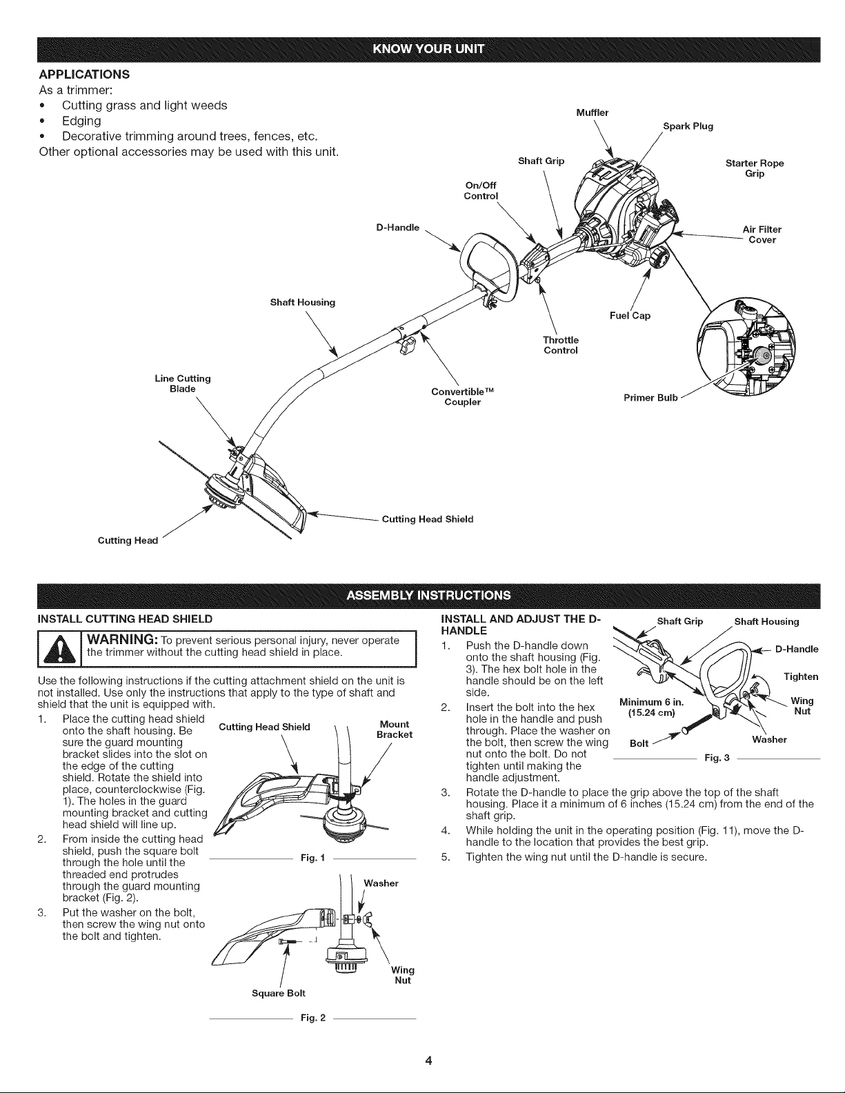
APPLICATIONS
As a trimmer:
• Cutting grass and light weeds
Edging
Decorative trimming around trees, fences, etc.
Other optional accessories may be used with this unit.
On/Oft
Control
Shaft Grip
Muffler
Spark Plug
Starter Rope
Grip
D-Handle
Shaft Housing
Line Cutting
Blade
\
Cutting Head Shield
Cutting Head
INSTALL CUTTING HEAD SHIELD
-- i_L_ ARNING: To prevent serious personal injury, never operate
Use the following instructions ifthe cutting attachment shield on the unit is
not installed. Use only the instructions that apply to the type of shaft and
shield that the unit is equipped with.
1. Place the cutting head shield
2. From inside the cutting head
3. Put the washer on the bolt,
the trimmer without the cutting head shield in place.
onto the shaft housing. Be
sure the guard mounting
bracket slides into the slot on
the edge of the cutting
shield. Rotate the shield into
place, counterclockwise (Fig.
1). The holes in the guard
mounting bracket and cutting
head shield will line up.
shield, push the square bolt
through the hole until the
threaded end protrudes
through the guard mounting
bracket (Fig. 2).
then screw the wing nut onto
the bolt and tighten.
Cutting Head Shield Mount
Bracket
Fig. I
Washer
Air Filter
Cover
Fuel Cap
Throttle
Controm
Convertible TM
Coupler Primer Bulb
INSTALLAND ADJUSTTHED-
HANDLE
1. PushtheD-handledown
onto the shaft housing (Fig.
3). The hex bolt hole in the
handle should be on the left
side.
2.
Insert the bolt into the hex
hole in the handle and push
through. Place the washer on
the bolt, then screw the wing
nut onto the bolt. Do not
tighten until making the
handle adjustment.
3. Rotate the D-handle to place the grip above the top of the shaft
housing. Place it a minimum of 6 inches (15.24 cm) from the end of the
shaft grip.
4. While holding the unit in the operating position (Fig. 11), move the D-
handle to the location that provides the best grip.
5. Tighten the wing nut until the D-handle is secure.
Shaft Grip Shaft Housing
Fig. 3
Tighten
Square Bolt
Nut
Fig. 2
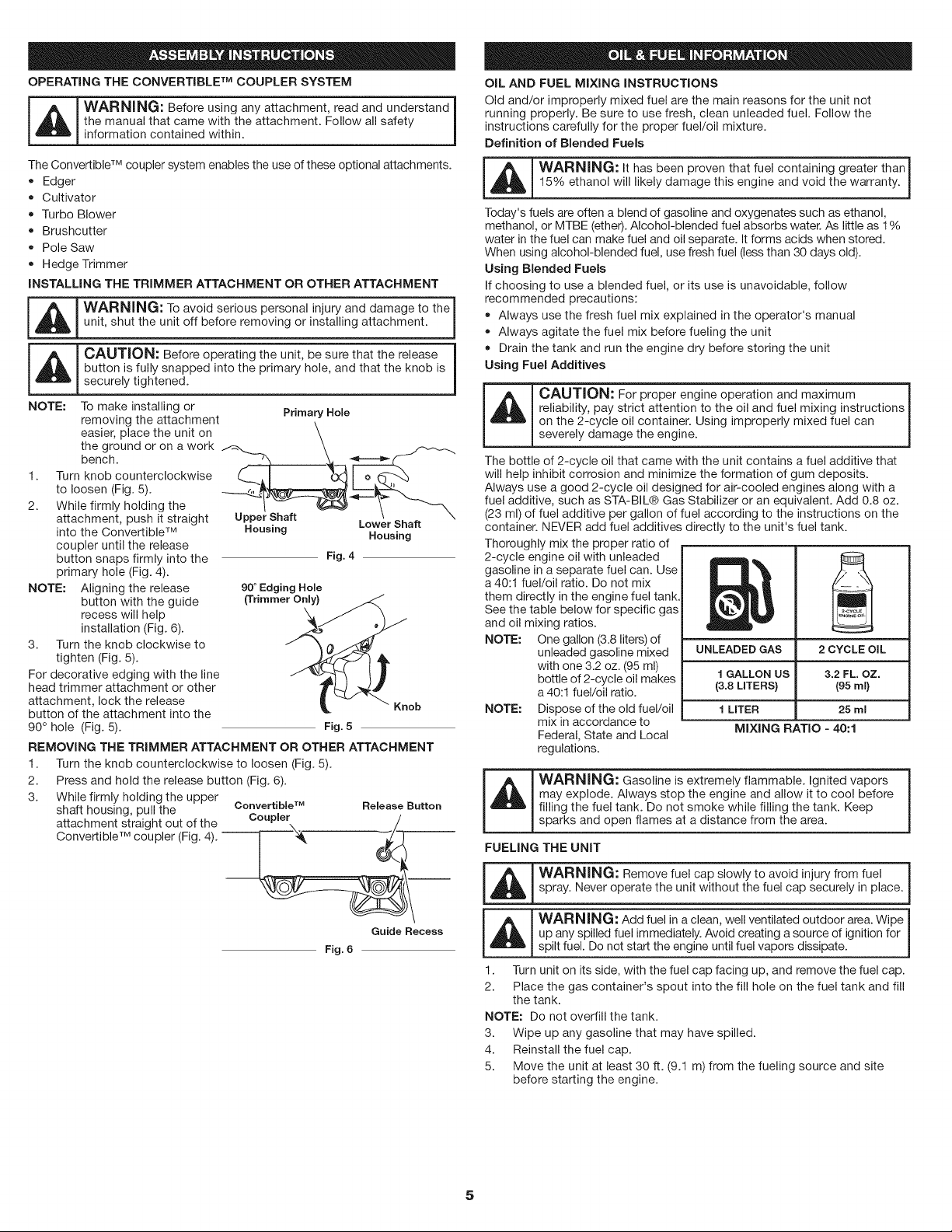
OPERATING THE CONVERTIBLE TM COUPLER SYSTEM
the manual that came with the attachment. Follow all safety |
WARNING: Before using any attachment, read and understand I
information contained within.
The Convertible TM coupler system enables the use of these optional attachments.
• Edger
Cultivator
Turbo Blower
Brushcutter
Pole Saw
Hedge Trimmer
INSTALLING THE TRIMMER ATTACHMENT OR OTHER ATTACHMENT
m
I _, I WARNING" To avoid serious personal injury and damage to the I
_ unit, shut the unit off before removing or installing attachment.
_ CAUTION: Before operating the unit, be sure that the release 1
NOTE: To make installing or Primary Hole
1. Turn knob counterclockwise _,, .lj____ _
2. While firmly holding the
NOTE: Aligning the release
3. Turn the knob clockwise to
For decorative edging with the line
head trimmer attachment or other
attachment, lock the release
button of the attachment into the
90° hole (Fig. 5).
REMOVING THE TRIMMER ATTACHMENT OR OTHER ATTACHMENT
1. Turn the knob counterclockwise to loosen (Fig. 5).
2. Press and hold the release button (Fig. 6).
3.
button is fully snapped into the primary hole, and that the knob is
securely tightened.
removing the attachment
the ground or on a work
easier, place the unit on _ _, _---_¢--"_"
bench.
to loosen (Fig. 5).
attachment, push it straight Upper Shaft Lower Shaft
into the Convertible TM
coupler until the release
button snaps firmly into the
primary hole (Fig. 4).
button with the guide
recess will help
installation (Fig. 6).
tighten (Fig. 5).
While firmly holding the upper
shaft housing, pull the
attachment straight out of the
Convertible TM coupler (Fig. 4). --
Housing
90° Edging Hole
(Trimmer Only}
Convertible TM Release Button
Coupler
Housing
Fig. 4
Fig. 5
OiL AND FUEL MIXING INSTRUCTIONS
Old and/or improperly mixed fuel are the main reasons for the unit not
running properly. Be sure to use fresh, clean unleaded fuel. Follow the
instructions carefully for the proper fuel/oil mixture.
J
Definition of Blended Fuels
m i_[_ ARN|NG: It has been proven that fuel containing greater than
Today's fuels are often a blend of gasoline and oxygenates such as ethanol,
methanol, or MTBE (ether). Alcohol-blended fuel absorbs water. As little as 1%
water in the fuel can make fuel and oil separate. It forms acids when stored.
When using alcohol-blended fuel, use fresh fuel (less than 30 days old).
Using Blended Fuels
If choosing to use a blended fuel, or its use is unavoidable, follow
recommended precautions:
• Always agitate the fuel mix before fueling the unit
• Drain the tank and run the engine dry before storing the unit
Using Fuel Additives
_ CAUTION: For proper engine operation and maximum
The bottle of 2-cycle oil that came with the unit contains a fuel additive that
will help inhibit corrosion and minimize the formation of gum deposits.
Always use a good 2-cycle oil designed for air-cooled engines along with a
fuel additive, such as STA-BIL® Gas Stabilizer or an equivalent. Add 0.8 oz.
(23 ml) of fuel additive per gallon of fuel according to the instructions on the
container. NEVER add fuel additives directly to the unit's fuel tank.
Thoroughly mix the proper ratio of
2-cycle engine oil with unleaded
gasoline in a separate fuel can. Use
a 40:1 fuel/oil ratio. Do not mix
them directly inthe engine fuel tank.
See the table below for specific gas
and oil mixing ratios.
NOTE: One gallon (3.8 liters) of
NOTE: Dispose of the old fuel/oil
_ WARN|NG: Gasoline is extremely flammable. Ignited vapors
FUELING THE UNIT
15% ethanol will likely damage this engine and void the warranty.
Always use the fresh fuel mix explained in the operator's manual
reliability, pay strict attention to the oil and fuel mixing instructions
on the 2-cycle oil container. Using improperly mixed fuel can
severely damage the engine.
unleaded gasoline mixed
with one 3.2 oz. (95 ml)
bottle of 2-cycle oil makes
a 40:1 fuel/oil ratio.
mix in accordance to
Federal, State and Local
regulations.
may explode. Always stop the engine and allow it to cool before
filling the fuel tank. Do not smoke while filling the tank. Keep
sparks and open flames at a distance from the area.
UNLEADED GAS
f GALLON US
(3.8 LITERS}
f LITER
MIXING RATIO =40:1
2 CYCLE OIL
3.2 FL OZ.
195ml)
25 ml
Fig. 6
Guide Recess
_ WARN|NG: Remove fuel cap slowly to avoid injury from fuel
_ WARNING: Add fuel in a clean, well ventilated outdoor area. Wipe
1. Turn unit on its side, with the fuel cap facing up, and remove the fuel cap.
2. Place the gas container's spout into the fill hole on the fuel tank and fill
NOTE: Do not overfill the tank.
3. Wipe up any gasoline that may have spilled.
4. Reinstall the fuel cap.
5. Move the unit at least 30 ft. (9.1 m) from the fueling source and site
spray. Never operate the unit without the fuel cap securely in place.
up any spilled fuel immediately. Avoid creating a source of ignition for
spilt fuel. Do not start the engine until fuel vapors dissipate.
the tank.
before starting the engine.
5
m
A I WARNING: Operate this unit only ina well-ventilated outdoor area.
_ Carbon monox de exhaust fumes can be etha n a conf ned area. j
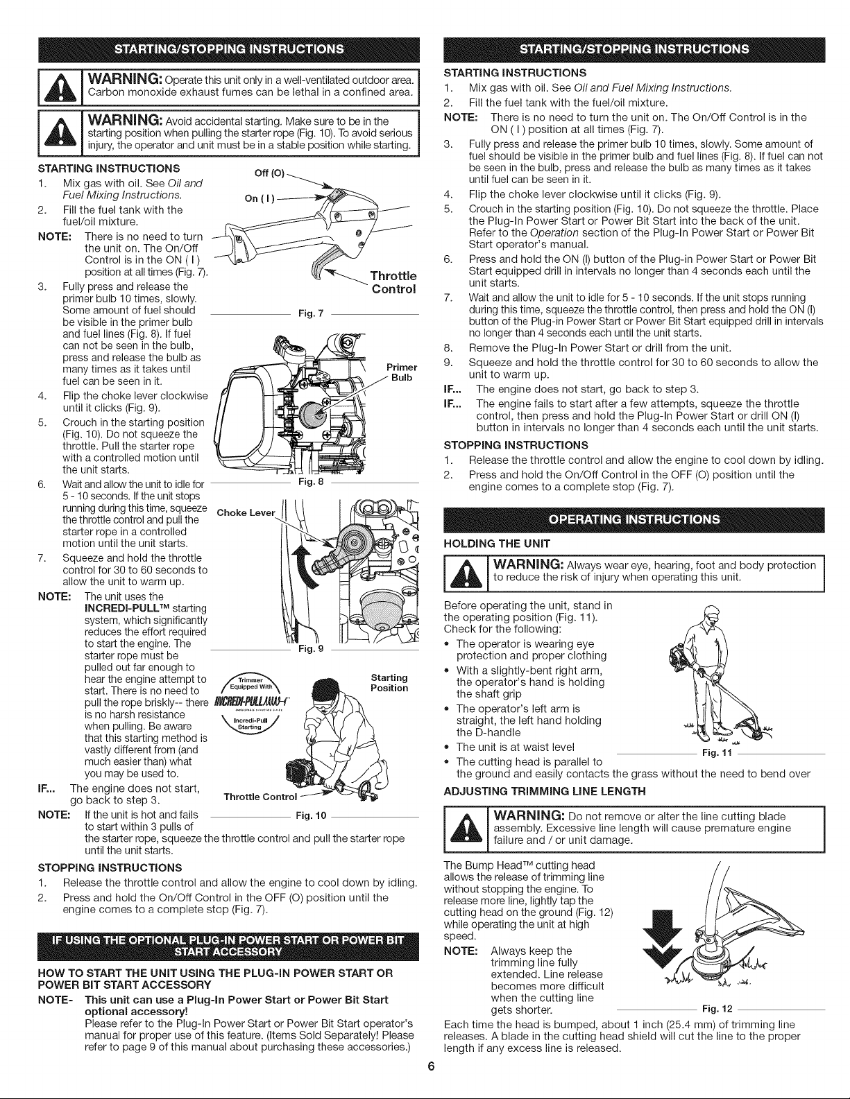
_llb I WARNING: Avoid accidental starting. Make sure to be in the !
STARTING iNSTRUCTiONS
1. Mix gas with oil. See Oil and
2. Fill the fuel tank with the
NOTE: There is no need to turn
3. Fully press and release the
4. Flip the choke lever clockwise
5. Crouch in the starting position
6. Waitand allow the unit to idlefor
7. Squeeze and hold the throttle
NOTE: The unit uses the
IF,.. The engine does not start,
NOTE: If the unit is hot and fails
STOPPING INSTRUCTIONS
1. Release the throttle control and allow the engine to cool down by idling.
2. Press and hold the On/Off Control in the OFF (O) position until the
HOW TO START THE UNIT USING THE PLUG=IN POWER START OR
POWER BiT START ACCESSORY
NOTE= This unit can use a Plug-in Power Start or Power Bit Start
starting position when pulling the starter rope (Fig. 10).Toavoid serious
! injury, the operator and unit must be in a stable position while starting.
off (o)-__
Fuel Mixing Instructions.
fuel/oil mixture.
the unit on. The On/Off
Control is in the ON ( I )
position at all times (Fig. 7).
primer bulb 10 times, slowly.
Some amount of fuel should
be visible in the primer bulb
and fuel lines (Fig. 8). If fuel
can not be seen in the bulb,
press and release the bulb as
many times as it takes until
fuel can be seen in it.
until it clicks (Fig. 9).
(Fig. 10). Do not squeeze the
throttle. Pull the starter rope
with a controlled motion until
the unit starts.
5 -10 seconds. If the unit stops
running during this time, squeeze Choke LeverJ
the throttle control and pullthe
starter rope in a controlled
motion until the unit starts.
control for 30 to 60 seconds to
allow the unit to warm up.
INCREDI=PULL TM starting
system, which significantly
reduces the effort required
to start the engine. The
starter rope must be
pulled out far enough to
hear the engine attempt to
start. There is no need to / =qu,pp_o,,m\
pull the rope briskly-- there I_-P_L4g/Jd _
is no harsh resistance ........................
when pulling. Be aware _ncr_!-Pu.
that this starting method is
vastly different from (and
much easier than) what
you may be used to.
go back to step 3.
to start within 3 pulls of
the starter rope, squeeze the throttle control and pull the starter rope
until the unit starts.
engine comes to a complete stop (Fig. 7).
optional accessory!
Please refer to the Plug-In Power Start or Power Bit Start operator's
manual for proper use of this feature. (Items Sold Separately! Please
refer to page 9 of this manual about purchasing these accessories.)
/
_(_ Throttle
Fig. 7
Fig. 8
Fig. 9
Fig. 10
Control
Primer
Bulb
Starting
Position
STARTING INSTRUCTIONS
i
1. Mix gas with oil. See Oil and Fuel Mixing Instructions.
2. Fill the fuel tank with the fuel/oil mixture.
NOTE: There is no need to turn the unit on. The On/Off Control is in the
ON (I) position at all times (Fig. 7).
3. Fully press and release the primer bulb 10 times, slowly. Some amount of
fuel should be visible in the primer bulb and fuel lines (Fig. 8). If fuel can not
be seen in the bulb, press and release the bulb as many times as it takes
until fuel can be seen in it.
4. Flip the choke lever clockwise until it clicks (Fig. 9).
5. Crouch in the starting position (Fig. 10). Do not squeeze the throttle. Place
the Plug-In Power Start or Power Bit Start into the back of the unit.
Refer to the Operation section of the Plug-In Power Start or Power Bit
Start operator's manual.
6. Press and hold the ON (I) button of the Plug-in Power Start or Power Bit
Start equipped drill in intervals no longer than 4 seconds each until the
unit starts.
7. Wait and allow the unit to idle for 5 - 10 seconds. Ifthe unit stops running
during this time, squeeze the throttle control, then press and hold the ON (I)
button of the Plug-in Power Start or Power Bit Start equipped drill in intervals
no longer than 4 seconds each until the unit starts.
8. Remove the Plug-In Power Start or drill from the unit.
9. Squeeze and hold the throttle control for 30 to 60 seconds to allow the
unit to warm up.
IF,.. The engine does not start, go back to step 3.
IF,.. The engine fails to start after a few attempts, squeeze the throttle
control, then press and hold the Plug-In Power Start or drill ON (I)
button in intervals no longer than 4 seconds each until the unit starts.
STOPPING INSTRUCTIONS
1. Release the throttle control and allow the engine to cool down by idling.
2. Press and hold the On/Off Control in the OFF (O) position until the
engine comes to a complete stop (Fig. 7).
HOLDING THE UNIT
-- i_L_ ARNING: Always wear eye, hearing, foot and body protection
Before operating the unit, stand in
the operating position (Fig. 11).
Check for the following:
• The operator is wearing eye
ADJUSTING TRIMMING LINE LENGTH
_ WARNING: Do not remove or alter the line cutting blade |
The Bump Head TM cutting head
allows the release of trimming line
without stopping the engine. To
release more line, lightly tap the
cutting head on the ground (Fig. 12)
while operating the unit at high
speed.
NOTE: Always keep the
Each time the head is bumped, about 1 inch (25.4 mm) of trimming line
releases. A blade in the cutting head shield will cut the line to the proper
length if any excess line is released.
to reduce the risk of injury when operating this unit.
protection and proper clothing
With a slightly-bent right arm,
the operator's hand is holding
the shaft grip
The operator's left arm is
straight, the left hand holding
the D-handle
The unit is at waist level Fig. 11'_
The cutting head is parallel to
the ground and easily contacts the grass without the need to bend over
assembly. Excessive line length will cause premature engine
failure and / or unit damage.
trimming line fully
extended. Line release
becomes more difficult "_
when the cutting line
gets shorter. Fig. 12
/
J
Forbestresults,tapthebumpknobonbaregroundorhardsoil.If
attemptingalinereleaseintallgrass,theenginemaystall.
NOTE:DonotresttheBumpHeadTM on the ground while the unit is running.
Some line breakage will occur from:
• Entanglement with foreign matter
• Normal line fatigue
Attempting to cut thick, stalky weeds
Forcing the line into objects such as walls or fence posts
TIPS FOR BEST TRIMMING RESULTS
Keep the cutting head parallel to the ground.
Do not force the cutting head. Allow the tip of the line to do the cutting,
especially along walls. Cutting with more than the tip will reduce cutting
efficiency and may overload the engine.
Cut grass over 8 inches (200 mm) by working from top to bottom in small
increments to avoid premature line wear or engine drag.
• Cut from right to left whenever possible. Cutting to the left improves the
unit's cutting efficiency. Clippings are thrown away from the operator.
• Slowly move the unit into and out of the cutting area at the desired height.
Move either in a forward-backward or side-to-side motion. Cutting shorter
lengths produces the best results.
Trim only when grass and weeds are dry.
• The life of the cutting line is dependent upon:
Following the trimming techniques
• What vegetation is being cut
• Where vegetation is cut
For example, the line will wear
faster when trimming against a
foundation wall as opposed to
trimming around a tree.
DECORATIVE TRIMMING
Decorative trimming is
accomplished by removing all ;300
vegetation around trees, posts,
fences, etc.. _
Rotate the whole unit so that the
cutting head is at a 30° angle to Fig. 13
the ground (Fig. 13).
MAINTENANCE SCHEDULE
maintenance or repairs with unit running. Always service and
repair a cool unit. Disconnect the spark plug wire to ensure that
WARNING: To prevent serious injury, never perform
the unit cannot start.
Perform these required maintenance procedures at the frequency stated in
the table. These procedures should also be a part of any seasonal tune-up.
NOTE: Some maintenance procedures may require special tools or skills. If
NOTE: Maintenance, replacement, or repair of the emission control devices
FREQUENCY MAINTENANCE REQUIRED SEE
Before starting engine Fill fuel tank with fresh fuel p. 5
Every 10 hours Clean and re-oil air filter p. 8
Every 25 hours Check spark plug condition and gap p. 8
LINE INSTALLATION
-- ]WARNING: Never use metal-reinforced line, wire, chain or
This section covers both SplitLine® and standard single line installation.
Always use original equipment manufacturer 0.095 in. (2.41 ram}
replacement line. Line other than the specified may make the engine
overheat or fail.
unsure about these procedures take the unit to Craftsman or other
qualified service dealer. Call 1-800-4-MY-HOME ®for more information.
and system may be performed by a Craftsman or other qualified
service dealer. Call 1=800=4=MY-HOME ®for more information.
rope. These can break off and become dangerous projectiles.
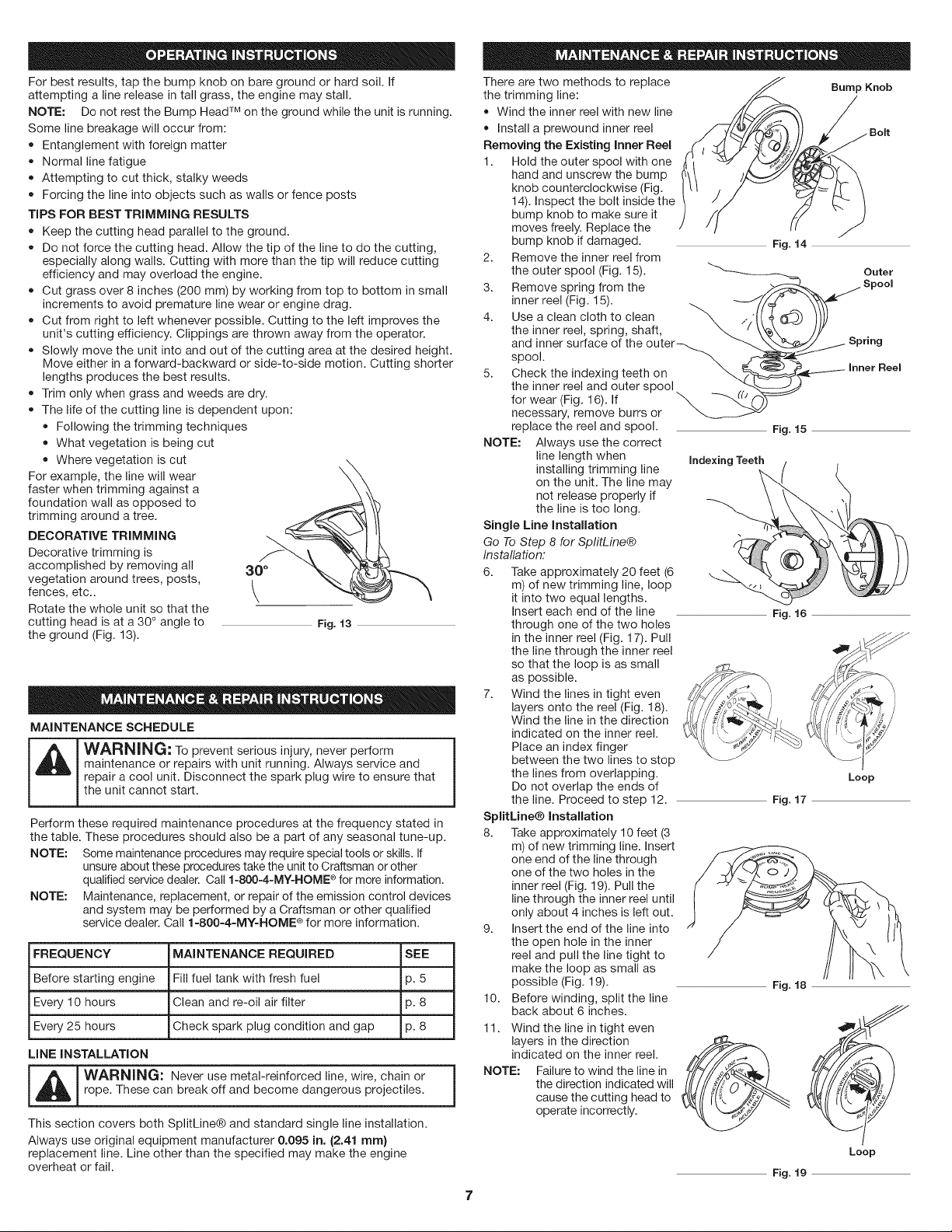
There are two methods to replace
the trimming line:
• Wind the inner reel with new line
Install a prewound inner reel
Removing the Existing inner Reel
1. Hold the outer spool with one
hand and unscrew the bump
knob counterclockwise (Fig.
14). Inspect the bolt inside the
bump knob to make sure it
moves freely. Replace the
bump knob if damaged.
2. Remove the inner reel from
the outer spool (Fig. 15).
3. Remove spring from the
inner reel (Fig. 15).
4.
Use a clean cloth to clean \ ,.
the inner reel, spring, shaft,
and inner surface of the outer_
spool.
Check the indexing teeth on
the inner reel and outer spool
for wear (Fig. 16). If
necessary, remove burrs or
replace the reel and spool.
NOTE: Always use the correct
Single Line installation
Go To Step 8 for SplitLine®
Installation:
6. Take approximately 20 feet (6
7. Wind the lines in tight even
SplitUne® installation
8. Take approximately 10 feet (3
9. Insert the end of the line into
10. Before winding, split the line
11. Wind the line in tight even
NOTE: Failure to wind the line in
line length when
installing trimming line
on the unit. The line may
not release properly if
the line is too long.
m) of new trimming line, loop
it into two equal lengths.
Insert each end of the line
through one of the two holes
in the inner reel (Fig. 17). Pull
the line through the inner reel
so that the loop is as small
as possible.
layers onto the reel (Fig. 18).
Wind the line in the direction
indicated on the inner reel.
Place an index finger
between the two lines to stop
the lines from overlapping.
Do not overlap the ends of
the line. Proceed to step 12.
m) of new trimming line. Insert
one end of the line through
one of the two holes in the
inner reel (Fig. 19). Pull the
line through the inner reel until
only about 4 inches is left out.
the open hole in the inner
reel and pull the line tight to
make the loop as small as
possible (Fig. 19).
back about 6 inches. , _
layers in the direction ._
indicated on the inner reel. /H/i/
the direction indicated will
cause the cutting head to
operate incorrectly.
7
Bump Knob
Fig. 14
Outer
Spool
Spring
Inner Reel
Fig. 15
Indexing Teeth
Fig.16
Loop
Fig. 17
Fig. 18
Loop
Fig. 19
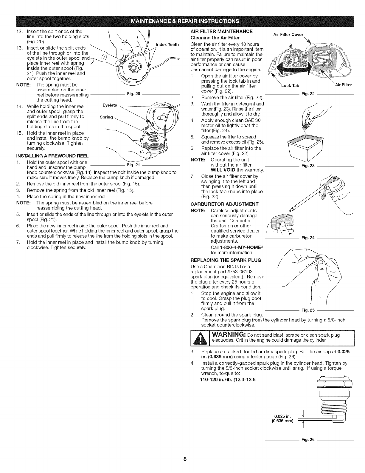
12. Insert the split ends of the
line into the two holding slots
(Fig. 20).
13. Insert or slide the split ends
of the line through or into the
eyelets in the outer spool
place inner reel with spring
inside the outer spool (Fig.
21). Push the inner reel and
outer spool together.
NOTE: The spring must be
14. While holding the inner reel
15. Hold the inner reel in place
INSTALLING A PREWOUND REEL
1. Hold the outer spool with one
2. Remove the old inner reel from the outer spool (Fig. 15).
3. Remove the spring from the old inner reel (Fig. 15).
4. Place the spring in the new inner reel.
NOTE: The spring must be assembled on the inner reel before
5. Insert or slide the ends of the line through or into the eyelets in the outer
6. Place the new inner reel inside the outer spool. Push the inner reel and
7. Hold the inner reel in place and install the bump knob by turning
assembled on the inner
reel before reassembling
the cutting head.
and outer spool, grasp the
split ends and pull firmly to
release the line from the
holding slots in the spool.
and install the bump knob by
turning clockwise. Tighten
securely.
hand and unscrew the bump Fig. 21
knob counterclockwise (Fig. 14). Inspect the bolt inside the bump knob to
make sure it moves freely. Replace the bump knob if damaged.
reassembling the cutting head.
spool (Fig. 21).
outer spool together. While holding the inner reel and outer spool, grasp the
ends and pull firmly to release the line from the holding slots in the spool.
clockwise. Tighten securely.
Eyelets
Fig. 20
Index Teeth
AiR FILTER MAINTENANCE
Cleaning the Air Filter
Clean the air filter every 10 hours
of operation. It is an important item
to maintain. Failure to maintain the
air filter properly can result in poor
performance or can cause
permanent damage to the engine.
1. Open the air filter cover by
pressing the lock tab in and
pulling out on the air filter
cover (Fig. 22).
2. Remove the air filter (Fig. 22).
3. Wash the filter in detergent and
water (Fig. 23). Rinse the filter
thoroughly and allow it to dry.
4. Apply enough clean SAE 30
motor oil to lightly coat the
filter (Fig. 24).
5. Squeeze the filter to spread
and remove excess oil (Fig. 25).
6. Replace the air filter into the
air filter cover (Fig. 22).
NOTE: Operating the unit
7. Close the air filter cover by
CARBURETOR ADJUSTMENT
NOTE: Careless adjustments
REPLACING THE SPARK PLUG
Use a Champion RDJ7J or a
replacement part #753-06193
spark plug (or equivalent). Remove
the plug after every 25 hours of
operation and check its condition.
1. Stop the engine and allow it
2. Clean around the spark plug.
m
without the air filter
WILL VOID the warranty.
swinging it to the left and
then pressing it down until
the lock tab snaps into place
(Fig. 22).
can seriously damage
the unit. Contact a
Craftsman or other
qualified service dealer
to make carburetor
adjustments.
Call 1-800=4=MY-HOME ®
for more information.
to cool. Grasp the plug boot
firmly and pull it from the
spark plug. Fig. 25
Remove the spark plug from the cylinder head by turning a 5/8-inch
socket counterclockwise.
Air Filter Cover
Lock Tab
Fig. 22
<
Fig. 23
Fig. 24
Air Filter
_L_ ARNING: Do not sand blast, scrape or clean spark plug
3.
4.
electrodes. Grit in the engine could damage the cylinder.
Replace a cracked, fouled or dirty spark plug. Set the air gap at 0.025
in. (0.635 rnrn) using a feeler gauge (Fig. 26).
Install a correctly-gapped spark plug in the cylinder head. Tighten by
turning the 5/8-inch socket clockwise until snug. If using a torque
wrench, torque to:
110=120 in.olb. (12.3=13.5
0.025 in.
(0.635ram) t
Fig. 26
Norn}. Do not over-tighten.
5. Reattach the plug boot.
TRANSPORTING
• Allow the engine to cool before transporting.
Drain fuel from unit.
Tighten fuel cap before transporting.
and allow itto cool before cleaning or maintaining it. |
WARNING: To avoid serious personal injury,always turn the unit off I
Secure the unit while transporting.
CLEANING
Use a small brush to clean offthe outside of the unit. Do not use strong
detergents. Household cleaners that contain aromatic oils such as pine and
lemon, and solvents such as kerosene, can damage plastic housing or handle.
Wipe off any moisture with a soft cloth.
STORAGE
Never store afueled unit where fumes may reach an open flame or spark.
Allow the engine to cool before storing.
Store the unit locked up to prevent unauthorized use or damage.
Store the unit in a dry, well-ventilated area.
Store the unit out of the reach of children.
LONG TERM STORAGE
If planning on storing the unit for an extended time, use the following storage
procedure:
1. Carefully drain the fuel tank by running the unit dry or remove fuel cap
and tip the motor housing over and drain oil/gas fuel into a container
with the same 2-cycle fuel mixture. Do not use fuel that has been stored
for more than 30 days.
2. Start the engine and allow it to run until it stalls. This ensures that all
fuel has been drained from the carburetor.
3. Allow the engine to cool. Remove the spark plug and put 1 oz. (30 ml)
of any high quality motor oil or 2-cycle oil into the cylinder. Pull the
starter rope slowly to distribute the oil. Reinstall the spark plug.
NOTE: Remove the spark plug and drain all of the oil from the cylinder before
4. Thoroughly clean the unit and inspect it for any loose or damaged
attempting to start the trimmer after storage.
parts. Repair or replace damaged parts and tighten loose screws, nuts
or bolts. The unit is ready for storage.
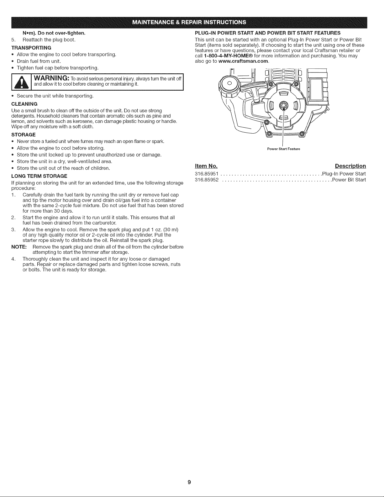
PLUG=IN POWER START AND POWER BiT START FEATURES
This unit can be started with an optional Plug-In Power Start or Power Bit
Start (items sold separately). If choosing to start the unit using one of these
features or have questions, please contact your local Craftsman retailer or
call 1=800=4=MY=HOME® for more information and purchasing. You may
also go to www.craftsrnan.corn.
J
Power Start Feature
item No. Description
316.85951 ..................................... Plug-In Power Start
316.85952 ........................................ Power Bit Start
9

PROBLEM SOLUTION
Empty fuel tank
Engine is flooded
Fouled spark plug
Air filter is plugged
Improper carburetor adjustment
Old or improperly mixed fuel
Dirty air filter
Old or improperly mixed fuel
Fouled spark plug
Engine overspeed protection engaged
Fill fuel tank with properly mixed fuel
Pull the starter rope while holding the throttle control
Replace the spark plug
Replace or clean the air filter
Take to a Craftsman or other qualified service dealer for adjustment
Drain fuel tank and add fresh fuel mixture
Clean or replace the air filter
Drain fuel tank and add fresh fuel mixture
Replace the spark plug
Allow the engine to cool down for 10 minutes before restarting
Cutting head bound with grass
Inner reel bound up
Line welded
Not enough line is exposed Push the bump knob and pull out line until 4 inches (102 mm) of line is
Oil, cleaner or lubricant in cutting head Clean and thoroughly dry the cutting head
Stop the engine and clean cutting head
Rewind the inner reel
Disassemble, remove the welded section and rewind
outside of the cutting head
HELP.
f.......
........... ! i_
YOu,,K find the answer and raore on mana_emvhfe°com - for free.
=
Find this and al your other product manuats onfne.
=
Get answers from our team of home experts.
= Get a personatzed maintenance ptan for your home.
=
Find information and tools to help with home projects.
.......... i
10
 Loading...