

Craftsman 316.790130 Operator's Manual
Operator’s Manual
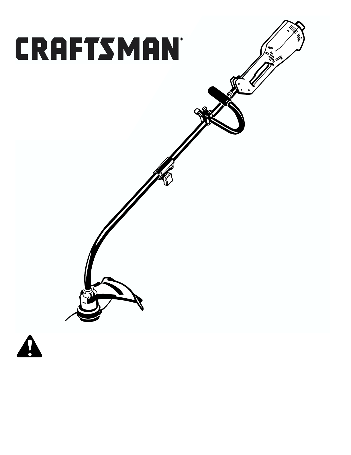
15-Inch/Curved Shaft/5.5 Amp Electric
WEEDWACKER
®
TRIMMER
Model No.
316.790130
Sears, Roebuck, and Co., Hoffman Estates, IL 60179 USA
OPERATOR'S MANUAL PART NO. 182317 Rev. A
PRINTED IN U.S.A. 5/99 (51569)
• Safety
• Assembly
• Operation
• Maintenance
• Español
Save this manual
for future reference.
WARNING:
Before using this product,
read this manual and follow
all its Safety Rules and Operating
Instructions.

– 2 –
SAFETY RULES
TABLE OF CONTENTS
WARRANTY STATEMENT
Warranty Statement 2
Safety Rules 2
Contents of Hardware Pack 6
Assembly 6
Operation 8
Maintenance 11
Service and Adjustments 12
Specifications 15
Troubleshooting 15
Español 16
FULL ONE-YEAR WARRANTY ON CRAFTSMAN®ELECTRIC WEEDWACKER®TRIMMER
For one year from the date of purchase, when this Craftsman Electric Weedwacker Trimmer is maintained according
to the operating and maintenance instructions in the operator's manual, Sears will repair, free of charge, any defect
in materials or workmanship.
This warranty excludes nylon line, bump knob, and line reels, which are expendable parts and become worn during normal
use.
If this Weedwacker Trimmer is used for commercial purposes, this warranty applies for 90 days from the date of purchase.
If this Weedwacker Trimmer is used for rental purposes, this warranty applies for 30 days from the date of purchase.
This warranty applies only while this product is in use in the United States.
WARRANTY SERVICE IS AVAILABLE BY RETURNING THE WEEDWACKER TRIMMER TO THE NEAREST SEARS SER-
VICE CENTER IN THE UNITED STATES.
This warranty gives you specific legal rights, and you may also have other rights which vary from state to state.
Sears, Roebuck and Co., D/817 WA, Hoffman Estates, IL 60179
WARNING: To guard against injury, basic
safety precautions should be observed,
including the following rules for safe operation:
The purpose of safety symbols is to attract your attention to possible dangers. The safety symbols, and their
explanations, deserve your careful attention and understanding. The safety warnings do not by themselves
eliminate any danger. The instructions or warnings they
give are not substitutes for proper accident prevention
measures.
SAFETY ALERT SYMBOL: Indicates
danger, warning, or caution. May be used in
conjunction with other symbols or pictographs.
DANGER: Failure to obey a safety warning
will result in serious injury to yourself or to
others. Always follow the safety precautions
to reduce the risk of fire, electric shock, and
personal injury.
WARNING: Failure to obey a safety warning
can result in serious injury to yourself or to
others. Always follow the safety precautions
to reduce the risk of fire, electric shock, and
personal injury.
CAUTION: Failure to obey a safety warning
may result in property damage or personal
minor or moderate injury to yourself or to others. Always follow the safety precautions to
reduce the risk of fire, electric shock, and personal injury.
NOTE: Advises you of information or instructions vital to

– 3 –
• IMPORTANT SAFETY INFORMATION •
WARNING: When using electric gardening
tool, basic safety precautions should always
be followed to reduce the risk of fire, electric
shock, and personal injury. Carefully read and
understand the entire Operator's Manual before
using your trimmer. Pay close attention to the
Operating Instructions and Safety Warnings.
READ ALL INSTRUCTIONS
ELECTRICAL SAFETY WARNINGS
• This tool is double-insulated. Use only identical
replacement parts when servicing. Repair or replace
damaged cords.
• WARNING: To reduce the risk of electrical shock, use
only extension cords approved for outdoor use, such
as an extension cord of cord type SW-A, SOW-A,
STW-A, STOW-A, SJW-A, SJOW-A, SJTW-W or
SJTOW-A. A 2-wire extension cord (an extension cord
without a ground) may be used because the tool is
double insulated. However, a 3-wire extension cord
(an extension cord with a ground) that uses a NEMA
type connector (parallel blade, U ground) may also be
used. Extension cords are available from your local
retailer. Use only round-jacketed extension cords
approved for outdoor use.
• To reduce the risk of electrical shock, this unit has a
polarized plug (one blade is wider than the other) and
will require the use of a polarized extension cord. This
unit plug will fit into a polarized extension cord only
one way. If the plug does not fit fully into the extension
cord, reverse the plug. If the plug still does not fit,
obtain a correct polarized extension cord. A polarized
extension cord will require the use of a polarized wall
outlet. This plug will fit into a polarized wall outlet only
one way. If the plug does not fit fully into the wall outlet, reverse the plug. If the plug still does not fit, contact a qualified electrician to install the proper wall outlet. Do not change the unit plug, extension cord receptacle, or extension cord plug in any way.
• Ground Fault Circuit Interrupter (GFCI) protection
should be provided on the circuit(s) or outlet(s) to be
used for this unit. Receptacles are available having
built-in GFCI protection and may be used for this measure of safety.
• CORD SETS: Make sure your cord set is in good condition. When using a cord set, be sure to use a cord
that is heavy enough to carry the current that your unit
will draw. An undersized cord set will cause a drop in
line voltage resulting in loss of power and overheating.
The table shows the correct size to use depending on
the cord length and nameplate amperage rating. If in
doubt, use the next heavier size line gauge. The smaller the gauge number, the heavier the cord. To reduce
the possibility of disconnection of the unit cord from
the cord set during operation, see Fig. 9.
•A nameplate on your unit indicates what voltage it
uses. Never connect the unit to an AC voltage that
differs from this voltage.
• Inspect all extension cords and the unit power
connection periodically. Look closely for deterioration,
cuts or cracks in the insulation. Also inspect the
connections for damage. Repair or replace the cords
if any defects appear.
• Avoid dangerous environments. Never operate your
unit in damp or wet conditions. Moisture is a shock
hazard.
• Do not use the unit in the rain.
• Do not handle the plug or the unit with wet hands.
BEFORE OPERATING
• Read the instructions carefully. Be familiar with the
controls and proper use of the unit.
• Do not operate this unit when tired, ill, or under the
influence of alcohol, drugs, or medication.
• Children and teens under the age of 15 must not use
the unit, except for teens guided by an adult.
• All guards and safety attachments must be installed
properly before operating the unit.
• Inspect the unit before use. Replace damaged parts.
Make sure all fasteners are in place and secure.
Replace parts that are cracked, chipped, or damaged
in any way. Do not operate the unit with loose or
damaged parts.
• Use only 0.080 in (2.03 mm) diameter genuine
Craftsman
®
replacement line. Never use
metal-reinforced line, wire, or rope, etc. These can
break off and become a dangerous projectile.
• Be aware of the risk of injury to the head, hands and
feet.
• Clear the area to be cut before each use. Remove all
objects such as rocks, broken glass, nails, wire, or
string which can be thrown or become entangled in
the cutting attachment.
• Clear the area of children, bystanders, and pets. At a
minimum, keep all children, bystanders and pets
outside a 50 feet (15 m.) radius; there still may be a
risk to bystanders from thrown objects. Bystanders
should be encouraged to wear eye protection. If you
are approached, stop the motor and cutting attachment immediately.
• Before each use, check that the cutting head is
correctly fixed and that the trigger returns automatically to the off position.
MINIMUM WIRE SIZE FOR EXTENSION CORDS FOR
120 VOLT APPLIANCES USING 0-6 AMPS
Cord length (ft) 25 50 100 150
Wire size (AWG) 16 16 16 14

– 4 –
WHILE OPERATING
• Wear safety glasses or goggles that are marked as
meeting ANSI Z87.1-1989 standards, and ear/hearing
protection when operating this unit. Wear a face or
dust mask if the operation is dusty. Long sleeve shirts
are recommended.
• Wear heavy, long pants, boots and gloves. Do not
wear short pants, sandals or go barefoot.
• Dress Properly – Do not wear loose clothing or jewelry.
They can be caught in moving parts. Secure hair
above
shoulder level.
• Stay Alert – Watch what you are doing. Use common
sense.
• Adjust the assist handle to your size to provide the
best grip.
• Be sure the cutting attachment is not in contact with
anything before starting the unit.
• The cutting attachment shield must always be in place
while operating the unit as a trimmer. Do not operate
unit without both trimming lines extended, and the
proper line installed. Do not extend the trimming line
beyond the length of the shield.
• Use the unit only in daylight or good artificial light.
Avoid accidental starting. Do not carry plugged-in unit
with your finger on the switch. Be sure switch is off
when plugging in.
• Do not abuse the power cord. Never carry the unit by
the cord or yank the plug out of the receptacle. Keep
the cord away from heat, oil and sharp edges.
• Use the right tool. Only use this tool for the purpose
intended. The line head cutting attachment with this
unit is designed only for cutting grass, light weeds and
decorative trimming. Do not use the attachment as
an edger.
• Do not overreach. Always keep proper footing and
balance.
• Always hold the unit with both hands when operating.
Keep a firm grip on both the front and rear handle or
grips.
• Keep hands, face, and feet at a distance from all
moving parts. Do not touch or try to stop the cutting
attachment when it is rotating.
• Do not operate the unit faster than the speed needed
to cut or trim. Do not run the unit at high speed when
not cutting.
• Always stop the unit when cutting is delayed or when
walking from one cutting location to another.
• If you strike or become entangled with a foreign
object, stop the unit immediately and check for damage. Do not operate before repairing damage. Do not
operate the unit with loose or damaged parts.
• Stop and switch the motor to off for maintenance,
repair, or for changing the cutting attachment or other
attachments.
• Use only genuine Craftsman
®
replacement parts
when servicing this unit. These parts are available
from your authorized service dealer. Do not use parts,
accessories or attachments not authorized by
Craftsman for this unit. Doing so could lead to
serious injury to the user, or damage to the unit, and
void your warranty.
• Keep unit clean of vegetation and other materials.
They may become lodged between the cutting attachment and shield.
OTHER SAFETY WARNINGS
• Disconnect the unit from the power supply when not in
use, before servicing, when changing accessories
such as cutting head, and the like.
• Maintain trimmer with care. Keep the unit clean and
serviced for the best and safest performance. Follow
the maintenance instructions. Always use a clean cloth
when cleaning. Never use strong detergents, gasoline,
petroleum-based products, or any strong solvents to
clean the unit.
• Keep your unit in good working condition. Follow
instructions for servicing and changing accessories.
Inspect unit periodically, and if damaged, have it
repaired by an authorized service facility. Inspect
extension cords periodically and replace if damaged.
Keep handles dry, clean, and free from oil and grease.
• Store the unit in a locked up and dry, or high and dry
place to prevent unauthorized use or damage. Keep
out of the reach of children.
• Never douse or squirt the unit with water or any other
liquid. Keep handles dry, clean and free from debris.
Clean after each use, see Cleaning and Storage
instructions.
• Keep these instructions. Refer to them often and use
them to instruct other users. If you loan someone this
unit, also loan them these instructions.
SAVE THESE INSTRUCTIONS

– 5 –
SAFETY AND INTERNATIONAL SYMBOLS
This operator's manual describes safety and international symbols and pictographs that may appear on this product.
Read the operator's manual for complete safety, assembly, operating and maintenance and repair information.
SYMBOL MEANING
• SAFETY ALERT SYMBOL
Indicates danger, warning, or caution. May be used with other symbols.
• READ OPERATOR’S MANUAL
Failure to follow operating instructions and safety precautions in operator's manual can
result in serious injury. Read operator's manual before starting or operating this unit.
• WEAR EYE AND HEARING PROTECTION
WARNING: Thrown objects and loud noise can cause severe eye injury and hearing loss. Wear
eye protection meeting ANSI Z87.1-1989 standards and ear protection when operating this unit.
• THROWN OBJECTS CAN CAUSE SEVERE INJURY
Do not operate unit without proper attachments and guards in place.
• KEEP CHILDREN AWAY
WARNING: Keep all bystanders, especially children and pets, at least 50 feet (15 m.)
from the operating area. Stop unit immediately if you are approached.
• SHARP BLADE
WARNING:
There is a sharp blade on the cutting attachment shield. To prevent serious injury,
do not touch blade.
• SPEED SWITCH
Indicates “HIGH” or “FASTEST” speed.
• SPEED SWITCH
Indicates “LOW” or “SLOWEST” speed.
WARNING: The operation of any power tool can result in foreign objects being thrown into
your eyes, which can result in severe eye damage. Before beginning power tool operation,
always wear safety goggles or safety glasses with side shields that are marked as meeting ANSI
Z87.1-1989 standards and a full face shield when needed. We recommend Wide Vision Safety
Mask for use over eyeglasses or standard safety glasses with side shields, available at Sears.
WEAR YOUR
SAFETY GLASSES
FORESIGHT IS BETTER
THAN NO SIGHT
– 6 –
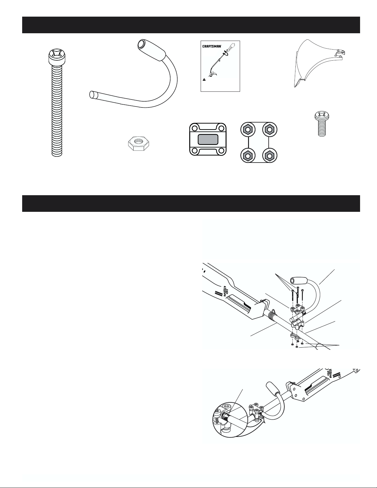
Middle
Handle
Clamp
Top Handle
Clamp
Assist Handle
Nuts
Shaft Housing
Bottom
Handle
Clamp
Screws
Decal
Fig. 1
Fig. 2
CONTENTS OF HARDWARE PACK
ASSEMBLY
Cutting Attachment Shield
Operator's Manual
Assist Handle
Middle Handle
Clamp
Top Handle
Clamp
(4) Hex Jam Nuts -(1/4 x 20)
for Assist Handle
(actual size)
(4) Screws (1/4-20 x 2-1/4)
- for Assist Handle
(actual size)
CARTON CONTENTS
• Trimmer
• Hardware Pack
ASSEMBLY INFORMATION
To ensure safe and proper operation of your unit, all
parts and hardware you assemble must be tightened
securely.
TOOLS REQUIRED FOR ASSEMBLY
• Large Phillips Screwdriver
• Regular Phillips Screwdriver
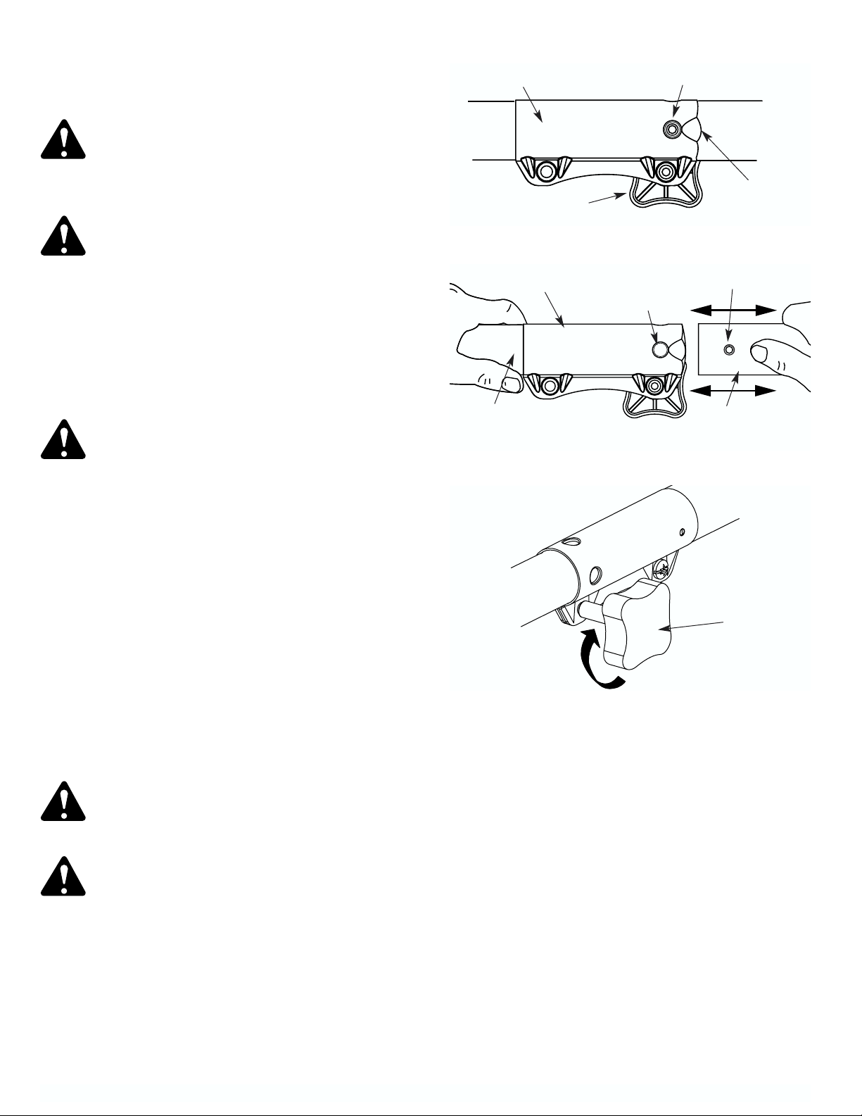
TO ASSEMBLE AND ADJUST ASSIST
HANDLE
1. Place the assist handle between the top and middle
clamp pieces (Fig. 1).
2. While holding the three pieces together, install the
four (4) screws through the top clamp and into middle clamp.
NOTE: The holes in the top and middle clamp will line up
only when assembled correctly.
3. Place the clamps and assist handle the over the
shaft housing and onto the bottom clamp.
4. Hold each hex nut in the bottom clamp recess with a
finger. Start screws with a large Phillips screwdriver.
Do not tighten until you make the handle adjustment.
5. Slide the assist handle in or out until the arrow/white
line on the decal touches the clamp assembly
(Fig. 2).
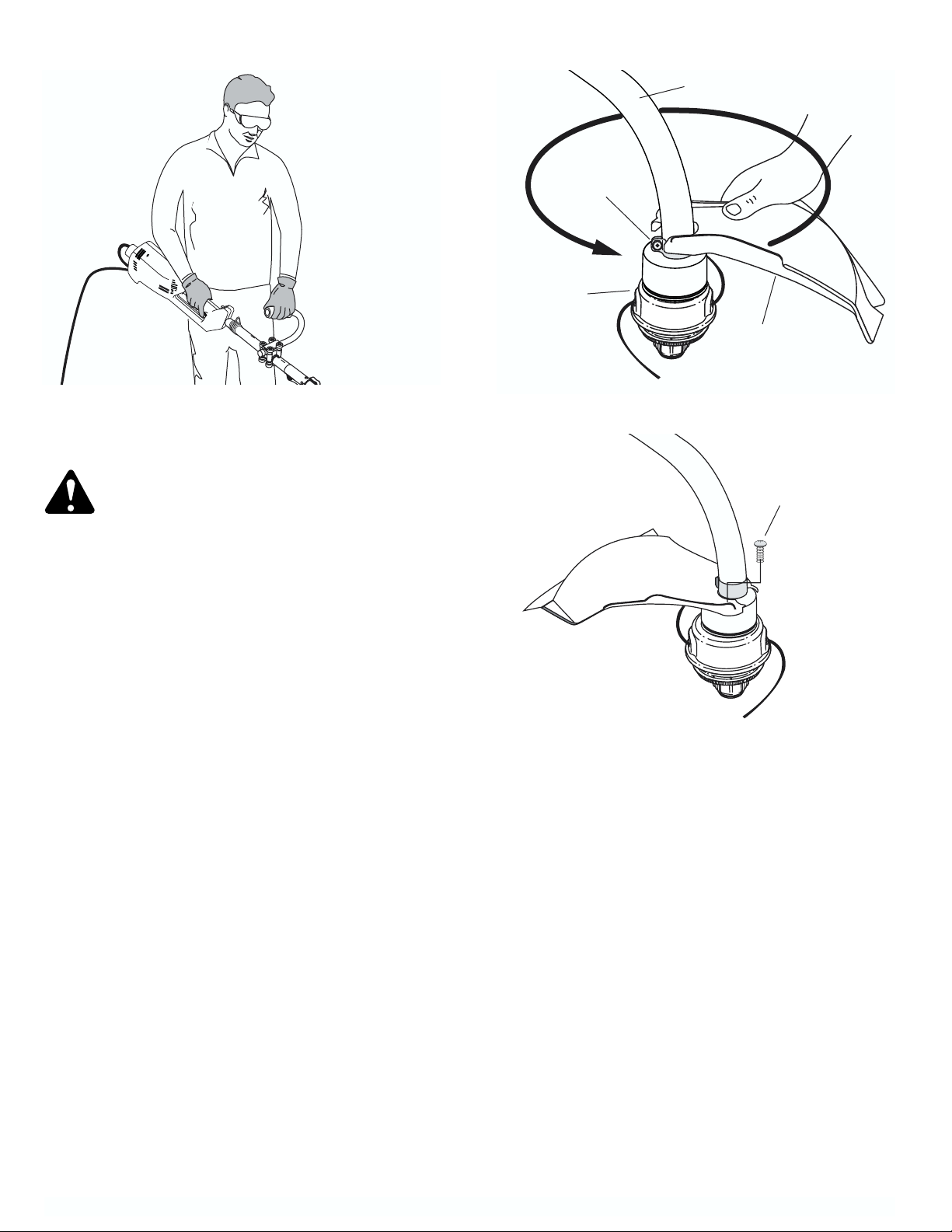
6. While holding the unit in the operating position
(Fig. 3), position the assist handle to the location
that provides you the best grip.
7. Tighten the clamp screws evenly, until the assist
handle is secure.
(4) Screws (10-24 x 1/2)
- for Cutting Attachment
Shield
(actual size)
Operator’s Manual
15-Inch Curved Shaft/5.5 Amp Electric
®
TRIMMER
WEEDWACKER
Model No.
316.790130
WARNING:
Before using this product,
read this manual and follow
all its Safety Rules and Operating
Instructions.
Sears, Roebuck, and Co., Hoffman Estates, IL 60179 USA
OPERATOR'S MANUAL PART NO. 182XXX Rev. A
PRINTED IN U.S.A. 5/99 (51569)
• Safety
• Assembly
• Operation
• Maintenance
• Español
Save this manual
for future reference.
– 7 –
Fig. 3
Fig. 4
Fig. 5
TO INSTALL CUTTING ATTACHMENT SHIELD
CAUTION: To avoid injury, never operate the
trimmer without the cutting attachment shield
installed. If the trimmer is operated without it in
place, you will VOID the warranty.
1. Place the cutting attachment shield onto the shaft housing
above the clamp assembly (Fig. 4).
2. Push the cutting attachment shield down to the top of the
cutting attachment assembly and then rotate the cutting
attachment shield 180°. Align the 4 screw holes and fit the
cutting attachment shield securely in the recessed pocket
(Fig. 4).
3. Install the four (4) screws (10-24 x 1/2) with a regular Phillips
screwdriver (Fig. 5). Tighten securely.
Screws
Cutting
Attachment
Shield
Cutting
Attachment
Clamp
Assembly
Shaft Housing
– 8 –
OPERATION
CUTTING
ATTACHMENT
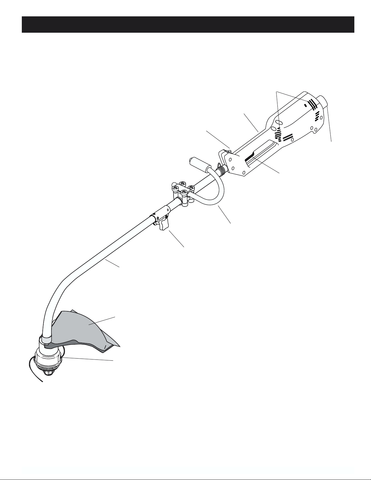
KNOW YOUR TRIMMER
READ THIS OPERATOR’S MANUAL AND SAFETY RULES BEFORE OPERATING YOUR UNIT. Compare the
illustrations with your unit to familiarize yourself with the location of various controls and adjustments.
Save this manual for future reference.
HOUSING GRIP
Air Vents
TWO SPEED
SWITCH
TRIGGER
ASSIST HANDLE
SHAFT
HOUSING
CUTTING
ATTACHMENT
SHIELD
COUPLER
RECESSED PLUG - is where you connect the extension
cord to the unit.
TRIGGER - used for starting and stopping the trimmer.
TWO SPEED SWITCH - used to switch between high
and low speeds for different cutting applications.
ASSIST HANDLE AND HOUSING GRIP - used to hold
the line trimmer during operation.
CUTTING ATTACHMENT SHIELD - protects operator
from thrown debris. Contains line cut-off blade to make
sure the line is not extended beyond its proper length.
Cutting attachment shield must be installed at all times
when using the cutting attachment.
CUTTING ATTACHMENT - consists of a reel housing,
reel, spring, Bump Knob, and cutting line
COUPLER - allows you to install optional attachments
on this unit.
RECESSED
PLUG
– 9 –
This trimmer has been designed and built to withstand
normal use. It will provide many hours of service provided the operating instructions are closely followed.
WARNING: Always wear eye, hearing, foot
and body protection to reduce the risk of injury
when operating this unit.
OPERATING THE COUPLER
WARNING:
To avoid serious personal
injury, shut off and unplug the unit before
removing or installing attachments.
This unit is equipped with a coupler, which enables
optional attachments to be installed. The optional
attachments are:
Edger . . . . . . . . . . . . . . . . . . . . . .Model No. 316.790401
Cultivator . . . . . . . . . . . . . . . . . . .Model No. 316.790410
Tree Pruner . . . . . . . . . . . . . . . . .Model No. 316.790430
Turbo Blower . . . . . . . . . . . . . . . .Model No. 316.790420
WARNING: Read and understand operator’s
manual for the attachment to be used with this
unit prior to operation.
NOTE: To make installing or removing the attachment
easier, place the unit on the ground or on a work bench.
Removing the Attachment:
1. Turn the knob counterclockwise to loosen (Fig. 6).
2. Press and hold the release button (Fig. 6).
3. While firmly holding the upper shaft housing, pull
the cutting attachment or optional attachment
straight out of the coupler (Fig. 7).
Installing the Attachment:
1. Turn the knob counterclockwise to loosen (Fig. 6).
2. While firmly holding the attachment, push it straight
into the coupler (Fig. 7).
NOTE: Aligning the release button with the guide recess
will help installation (Fig. 7).
3. Turn the knob clockwise to tighten (Fig. 8).
CAUTION: Lock the release button in the
primary hole and securely tighten the knob
before operating this unit.
CAUTION: The attachments with the coupler
are to be used in the primary hole unless stated
otherwise in the specific attachments operator’s manual. Using the wrong hole could lead
to
personal injury, or damage to the unit.
Release Button
Coupler
Guide
Recess
Knob
Knob
Coupler
Primary Hole
Upper Shaft
Housing
Lower Shaft
Housing
Release Button
Fig. 6
Fig. 7
Fig. 8
– 10 –
Fig. 11
Fig. 10
Fig. 9
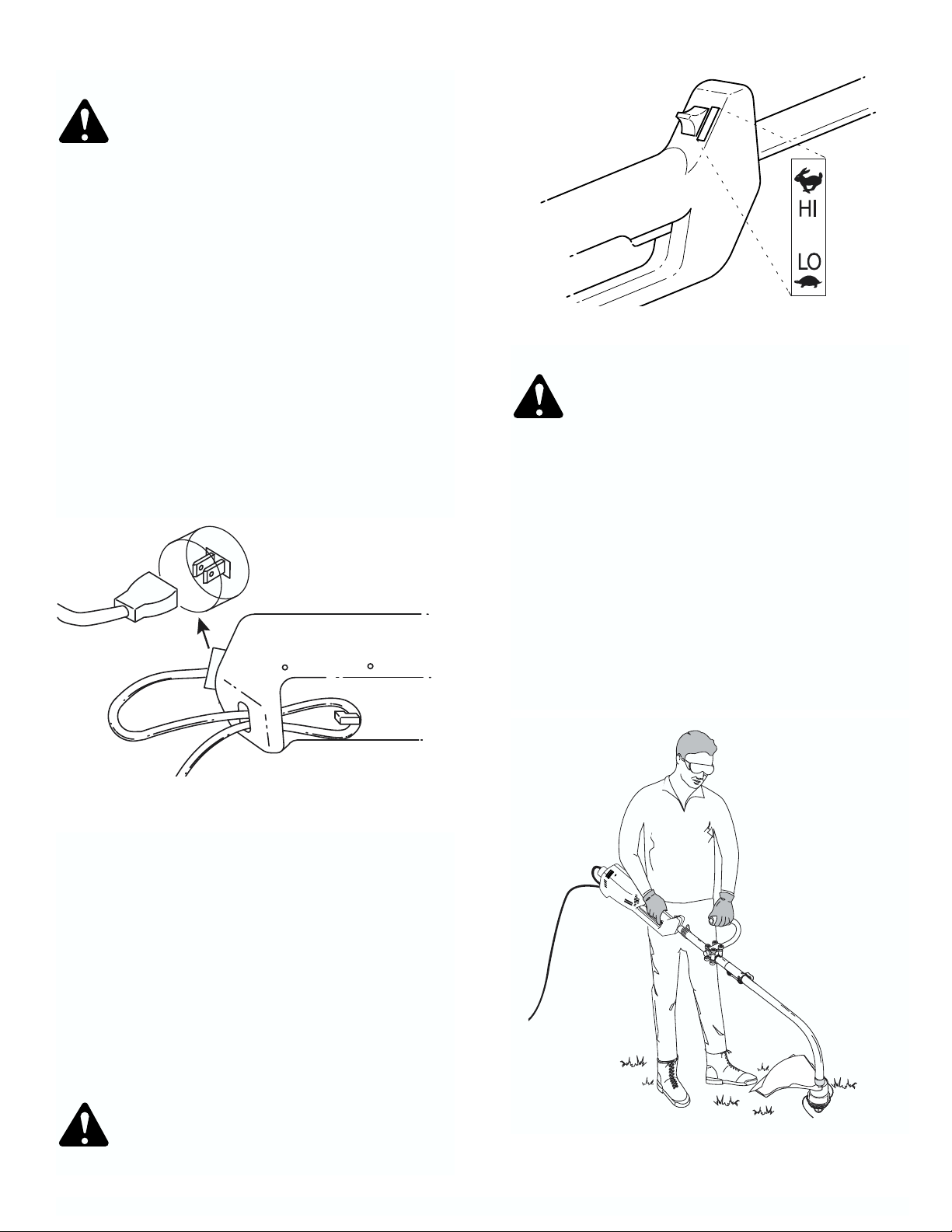
HOLDING THE TRIMMER
WARNING: Always wear eye, hearing, foot
and body protection to reduce the risk of injury
when operating this unit.
Before operating the unit, stand in the operating position
(Fig. 11). Check for the following:
• The operator is wearing eye protection and proper
clothing.
• The right arm is slightly bent, and the hand is holding
the housing grip.
• The left arm is straight, and the hand is holding the
assist handle.
• The unit is below waist level.
• The cutting attachment is parallel to the ground and
easily contacts the vegetation to be cut without the
operator having to bend over.
CONNECTING THE POWER CORD
WARNING: To reduce the risk of electrical
shock, this unit has a polarized plug (one blade
is wider than the other) and will require the use
of a polarized extension cord. This unit plug will
fit into a polarized extension cord only one way.
If the plug does not fit fully into the extension
cord, reverse the plug. If the plug still does not
fit, obtain a correct polarized extension cord. A
polarized extension cord will require the use of
a polarized wall outlet. This plug will fit into a
polarized wall outlet only one way. If the plug
does not fit fully into the wall outlet, reverse the
plug. If the plug still does not fit, contact a
qualified electrician to install the proper wall
outlet. Do not change the unit plug, extension
cord receptacle, or extension cord plug in any
way.
1. Use the cord hook when you connect the extension
cord to the power cord to prevent disconnection
(Fig. 9). Use only an outdoor-approved extension
cord as specified in the SAFETY RULES section.
2. Secure the extension cord to motor housing as
STARTING THE TRIMMER
Be in the operating position (Fig. 11). Squeeze the trigger
to start the trimmer.
STOPPING THE TRIMMER
Release the trigger to stop the trimmer.
OPERATING THE TWO-SPEED SWITCH
This unit is equipped with a two-speed switch;
a powerful high speed for demanding yard work, and
a precision low speed for light-duty yard work.
Push the switch up for high speed trimming. Push the
switch down for low speed trimming (Fig. 10).
CAUTION: Do not use the unit for demanding
yard work with the switch in the low speed.
This may cause the unit to overheat and fail.
 Loading...