

Craftsman 316.773800 Operator's Manual
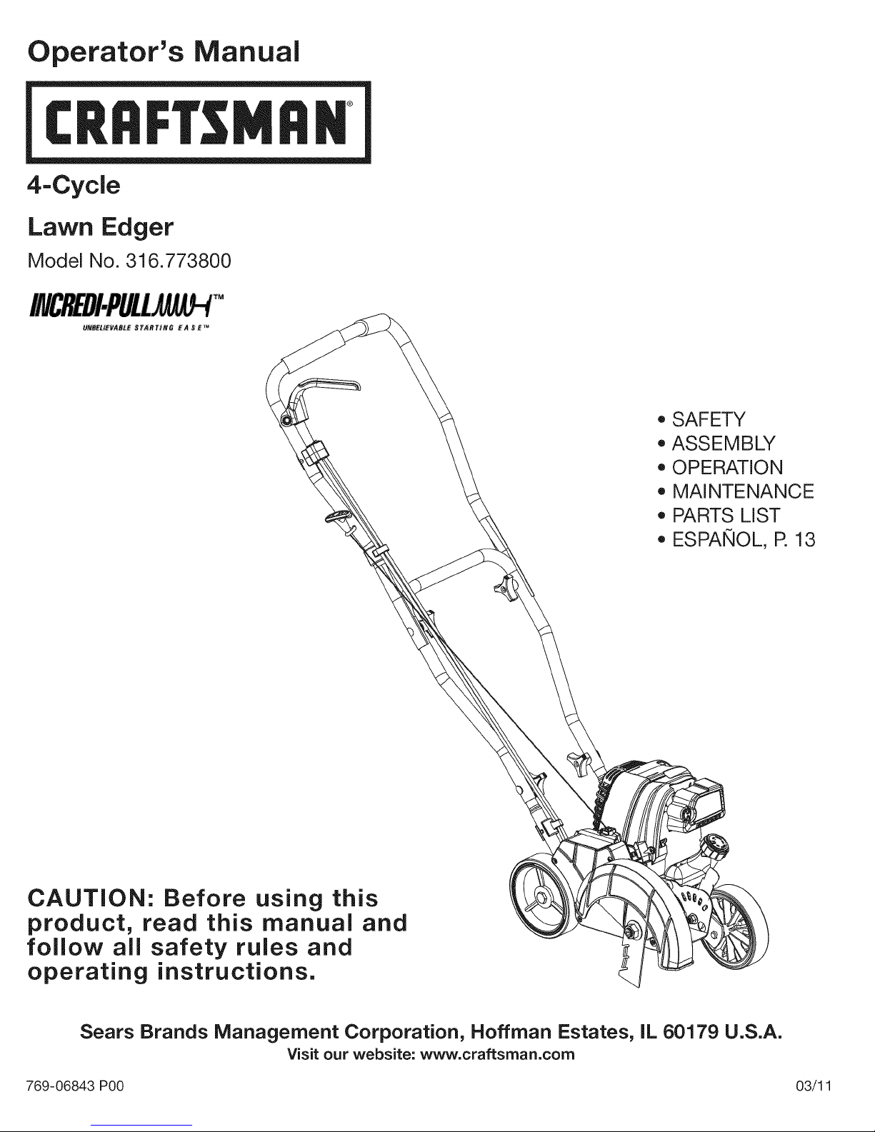
Operator's Manual
M
4-CycJe
Lawn Edger
Model No. 316.773800
,, SAFETY
* ASSEMBLY
* OPERATION
* MAINTENANCE
* PARTS LIST
CAUTION: Before using this
product, read this manual and
follow all safety rules and
operating instructions.
* ESPANOL, R 13
Sears Brands Management Corporation, Hoffman Estates, IL 60179 U.S.A.
Visit our website: www.craftsman.com
769-06843 P00 03/11
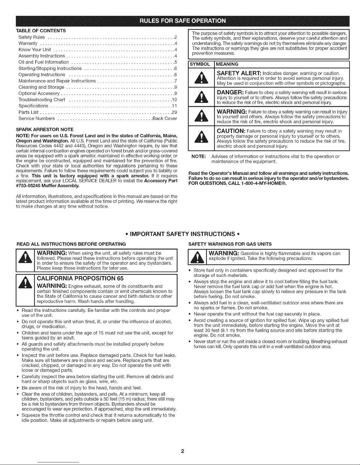
TABLE OF CONTENTS
Safety Rules ................................................. 2
Warranty .................................................... 4
Know Your Unit ............................................... 4
Assembly Instructions .......................................... 4
Oil and Fuel Information ........................................ 5
Starting/Stopping Instructions ................................... 6
Operating Instructions ......................................... 6
Maintenance and Repair Instructions .............................. 7
Cleaning and Storage .......................................... 9
Optional Accessory ............................................ 9
Troubleshooting Chart ........................................ 10
Specifications ............................................... 11
Parts List ................................................... 29
Service Numbers ..................................... Back Cover
SPARK ARRESTOR NOTE
NOTE: For users on U.S. Forest Land and in the states of California, Maine,
Oregon and Washington. All U.S. Forest Land and the state of California (Public
Resources Codes 4442 and 4443), Oregon and Washington require, by law that
certain internal combustion engines operated on forest brush and/or grass-covered
areas be equipped with a spark arrestor, maintained in effective working order, or
the engine be constructed, equipped and maintained for the prevention of fire.
Check with your state or local authorities for regulations pertaining to these
requirements. Failureto follow these requirements could subject you to liability or
a fine. This unit is factory equipped with a spark arrestor. If it requires
replacement, ask your LOCAL SERVICE DEALER to install the Accessory Part
#753=05245 Muffler Assembly.
All information, illustrations, and specifications in this manual are based on the
latest product information available at the time of printing. We reserve the right
to make changes at any time without notice.
The purpose of safety symbols is to attract your attention to possible dangers.
The safety symbols, and their explanations, deserve your careful attention and
understanding. The safety warnings do not by themselves eliminate any danger.
The instructions or warnings they give are not substitutes for proper accident
prevention measures.
SYMBOL MEANING
Attention is required in order to avoid serious personal injury.
SAFETY ALERT: Indicates danger, warning or caution.
May be used in conjunction with other symbols or pictographs.
injury to yourself orto others. Always follow the safety precautions
DANGER: Failure to obey a safety warning will result in serious
to reduce the risk of fire, electric shock and personal injury.
WARNING: Failure to obey a safety warning can result in injuryto yourself and others. Always follow the safety precautions to
reduce the risk of fire, electric shock and personal injury.
_1_ CAUTION: Failure to obey a safety warning may result in
NOTE: Advises of information or instructions vital to the operation or
Read the Operator's Manual and follow all warnings and safety instructions.
Failure to do so can result in serious injury to the operator and/or bystanders.
FOR QUESTIONS, CALL 1=800=4=MY=HOME®.
property damage or personal injury to yourself or to others.
Always follow the safety precautions to reduce the risk of fire,
electric shock and personal injury.
maintenance of the equipment.
• iMPORTANT SAFETY iNSTRUCTiONS
READ ALL INSTRUCTIONS BEFORE OPERATING
WARNING: When using the unit, all safety rules must be
followed. Please read these instructions before operating the unit
in order to ensure the safety of the operator and any bystanders.
Please keep these instructions for later use.
CALiFORNiA PROPOSiTiON 65
WARNING: Engine exhaust, some of its constituents and
certain finished components contain or emit chemicals known to
the State of California to cause cancer and birth defects or other
reproductive harm. Wash hands after handling.
• Read the instructions carefully. Be familiar with the controls and proper
use of the unit.
Do not operate this unit when tired, ill, or under the influence of alcohol,
drugs, or medication.
Children and teens under the age of 15 must not use the unit, except for
teens guided by an adult.
All guards and safety attachments must be installed properly before
operating the unit.
Inspect the unit before use. Replace damaged parts. Check for fuel leaks.
Make sure all fasteners are in place and secure. Replace parts that are
cracked, chipped, or damaged in any way. Do not operate the unit with
loose or damaged parts.
Carefully inspect the area before starting the unit. Remove all debris and
hard or sharp objects such as glass, wire, etc.
Be aware of the risk of injury to the head, hands and feet.
Clear the area of children, bystanders, and pets. At a minimum, keep all
children, bystanders, and pets outside a 50 feet (15 m) radius; there still may
be a risk to bystanders from thrown objects. Bystanders should be
encouraged to wear eye protection. If approached, stop the unit immediately.
Squeeze the throttle control and check that it returns automatically to the
idle position. Make all adjustments or repairs before using unit.
SAFETY WARNINGS FOR GAS UNITS
_L_WARNING: Gasoline is highly flammable and its vapors can I
exp ode f gn ted. Take the fo ow ng precaut ons: /
Store fuel only in containers specifically designed and approved for the
storage of such materials.
Always stop the engine and allow it to cool before filling the fuel tank.
Never remove the fuel tank cap or add fuel when the engine is hot.
Always loosen the fuel tank cap slowly to relieve any pressure in the tank
before fueling. Do not smoke.
• Always add fuel in a clean, well-ventilated outdoor area where there are
no sparks or flames. Do not smoke.
• Never operate the unit without the fuel cap securely in place.
Avoid creating a source of ignition for spilled fuel. Wipe up any spilled fuel
from the unit immediately, before starting the engine. Move the unit at
least 30 feet (9.1 m) from the fueling source and site before starting the
engine. Do not smoke.
Never start or run the unit inside a closed room or building. Breathing exhaust
fumes can kill. Only operate this unit in a well-ventilated outdoor area.
J
WHILEOPERATING +Ifstrikingorbecomesentangledwithaforeignobject,stoptheengine
+WearsafetyglassesorgogglesthataremarkedasmeetingANSIZ87.1-
1989standards.Alsowearear/hearingprotectionwhenoperatingthis
unit.Wearafaceordustmaskiftheoperationisdusty.Longsleeveshirts
arerecommended.
+Wearheavy,longpants,bootsandgloves.Donotwearlooseclothing,
jewelry,shortpants,sandalsorgobarefoot.Securehairaboveshoulderlevel.
+Thisunithasaclutch.Thebladeremainsstationarywhentheengineisidling.
Iftheydonot,havetheunitadjustedbyanauthorizedservicetechnician.
+Besurethebladeisnotincontactwithanythingbeforestartingtheunit.
+Usetheunitonlyindaylightorgoodartificiallight.
+Avoidaccidentalstarting.Beinthestartingpositionwheneverpullingthe
starterrope.Theoperatorandunitmustbeinastablepositionwhile
starting.SeeStarting/Stopping Instructions.
+ Use the right tool. Only use this tool for the purpose intended.
+ Use extreme caution when reversing or pulling the unit backwards.
+ Do not overreach. Always keep proper footing and balance. Take extra
care when working with on steep slopes or inclines.
+ Always hold the unit with both hands when operating. Keep a firm grip on
the handle.
+ Keep hands, face, and feet at a distance from all moving parts. Do not
touch or try to stop the blade while it is rotating.
+ Do not touch the engine or muffler. These parts get extremely hot from
operation. They remain hot for a short time after turning off the unit.
+ Do not operate the engine faster than the speed needed for the job. Do
not run the engine at high speed when the unit is not in use.
+ Always stop the engine when work is delayed or when walking from one
location to another.
immediately and check for damage. Do not operate before repairing
damage. Do not operate the unit with loose or damaged parts.
+ Stop and switch the engine to off for maintenance or repair
+ Use only original equipment manufacturer replacement parts and
accessories for this unit. These are available from an authorized service
dealer The use of any unauthorized parts or accessories could lead to
serious injury to the user, or damage to the unit, and void the warranty.
+ Keep unit clean of vegetation and other materials that may become
lodged or entangled in the unit.
+ To reduce fire hazard, keep the engine and muffler free from grass, leaves,
excessive grease or carbon build up.
AFTER USE
+ Clean the unit with household cleaner to remove any gum buildup. Oil the
blade with machine oil to prevent rust.
OTHER SAFETY WARNINGS
+ Never store a fueled unit inside a building where fumes may reach an
open flame or spark.
+ Allow the engine to cool before storing or transporting. Be sure to secure
the unit while transporting.
+ Store the unit in a dry area, locked up or up high to prevent unauthorized
use or damage. Keep out of the reach of children.
+ Never douse or squirt the unit with water or any other liquid. Keep handles
dry, clean and free from debris. Clean after each use. See the Cleaning
and Storage instructions.
+ Keep these instructions. Refer to them often and use them to instruct other
users. If loaning someone this unit, also loan them these instructions.
SAVE THESEINSTRUCTIONS
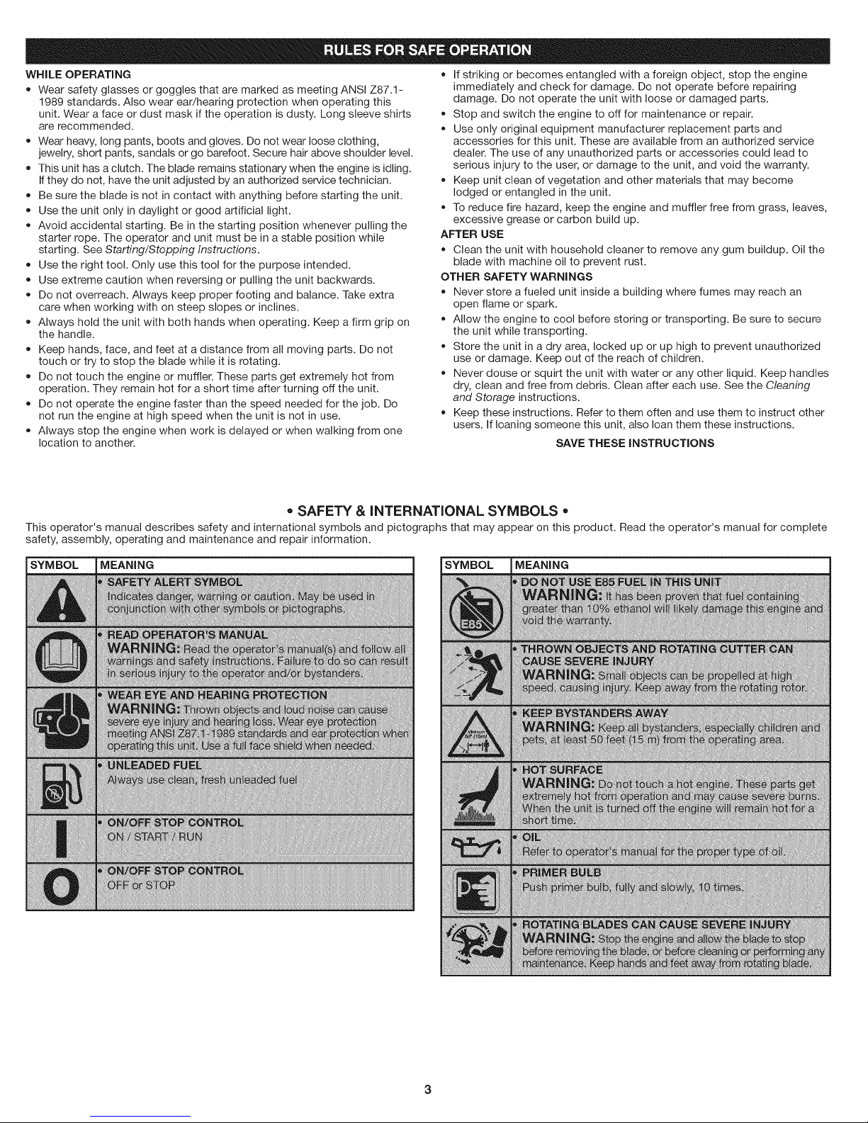
+ SAFETY & iNTERNATiONAL SYMBOLS +
This operator's manual describes safety and international symbols and pictographs that may appear on this product. Read the operator's manual for complete
safety, assembly, operating and maintenance and repair information.
SYMBOL MEANING SYMBOL MEANING
;;U_E;;;E
||NG
warran
_m
+ii_t
N
_+ii;;;;;;;;;iiii+i
ING:
c_p_rat
;St
3
CRAFTSMAN 2 YEAR FULL WARRANTY
FOR 2 YEARS from the date of purchase, this product is warranted against any defects in material or workmanship. Defective product will receive free repair or
free replacement if repair is unavailable.
For warranty coverage details to obtain repair or replacement, visit the web site: www.craftsman.com
This warranty covers ONLY defects in material and workmanship. Warranty coverage does NOT include:
• Expendable items that can wear out from normal use within the warranty period, such as edger blades, filters or spark plugs.
Product damage resulting from user attempts at product modification or repair or caused by product accessories.
Repairs necessary because of accident or failure to operate or maintain the product according to all supplied instructions.
Preventive maintenance, or repairs necessary due to improper fuel mixture, contaminated or stale fuel.
This warranty is void if this product is ever used while providing commercial services or if rented to another person.
This warranty gives you specific legal rights, and you may also have other rights, which vary from state to state.
Sears Brands Management Corporation, Hoffman Estates, IL 60179
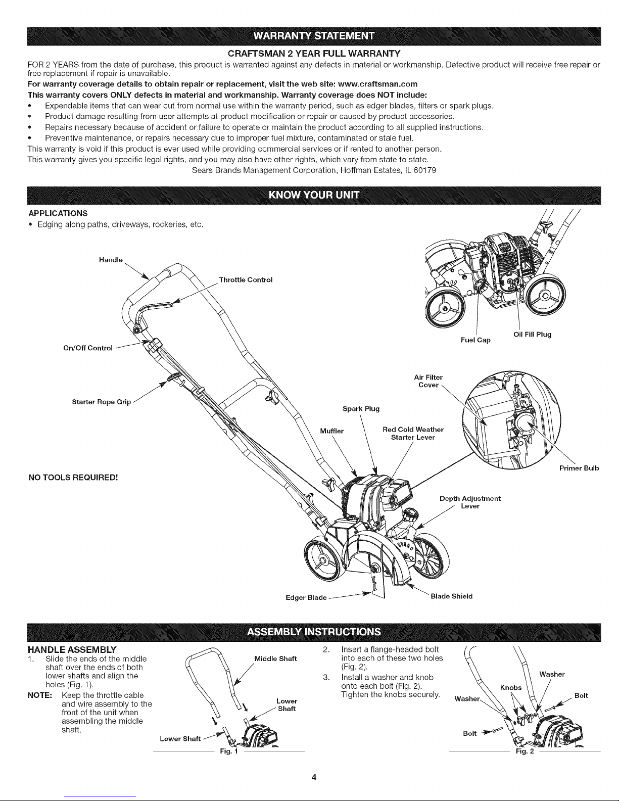
APPLiCATiONS
Edging along paths, driveways, rockeries, etc.
Handle
Throttle Control
On/Off Control
Starter Rope Grip
NO TOOLS REQUIRED!
Muffler
Edger Blade --_
Spark Plug
Air Filter
Cover
Red Cold Weather
Starter Lever
Fuel Cap
Depth Adjustment
Lever
Blade Shield
Oil Fill Plug
Primer Bulb
HANDLE ASSEMBLY
1. Slide the ends of the middle
shaft over the ends of both
lower shafts and align the
holes (Fig. 1).
NOTE: Keep the throttle cable
and wire assembly to the
front of the unit when
assembling the middle
shaft.
Middle Shaft into each of these two holes
2. Insert a flange-headed bolt
(Fig. 2).
3. Install a washer and knob
onto each bolt (Fig. 2).
Lower Washer,_
Shaft
Fig. 1 Fig. 2
Tighten the knobs securely.
Washer
Bolt
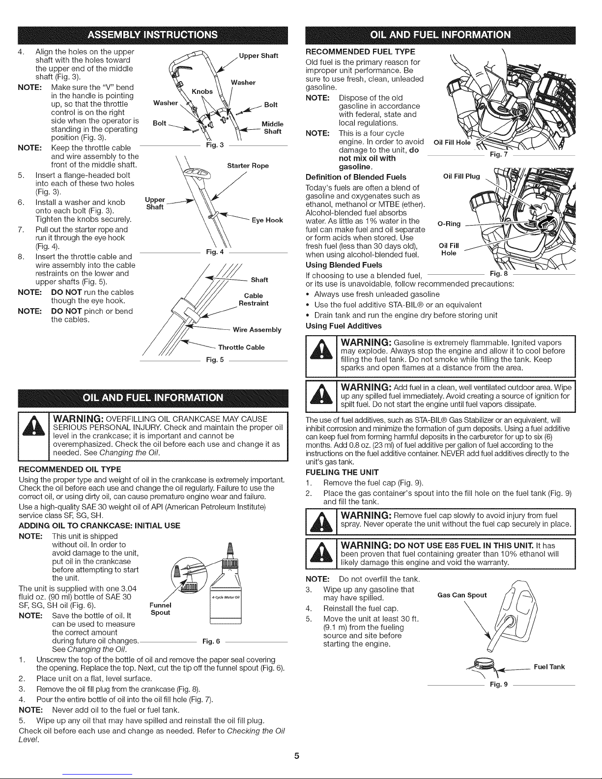
4. Align the holes on the upper _ /Upper Shaft
shaft with the holes toward
the upper end of the middle
shaft (Fig. 3).
NOTE: Make sure the "V" bend % ob _ _Nasher
NOTE: Keep the throttle cable Fig.3
5. Insert a flange-headed bolt
6. Install a washer and knob UPPa_tr
7. Pull out the starter rope and
8. Insert the throttle cable and Fig.4
NOTE: DO NOT run the cables Cable
NOTE: DO NOT pinch or bend
in the handle is pointing Kn s
up, so that the throttle Washer
control is on the right /____,_ f_ Holt
side when the operator is Bolt _ Middle
standing in the operating
position (Fig. 3). _ % \_---- Shaft
and wire assembly to the
front of the middle shaft. Starter Rope
into each of these two holes
(Fig. 3).
onto each bolt (Fig. 3).
Tighten the knobs securely. Eye Hook
run it through the eye hook
(Fig. 4).
wire assembly into the cable
restraints on the lower and
upper shafts (Fig. 5). Shaft
though the eye hook. Restraint
the cables.
Wire Assembly
Throttle Cable
Fig. 5
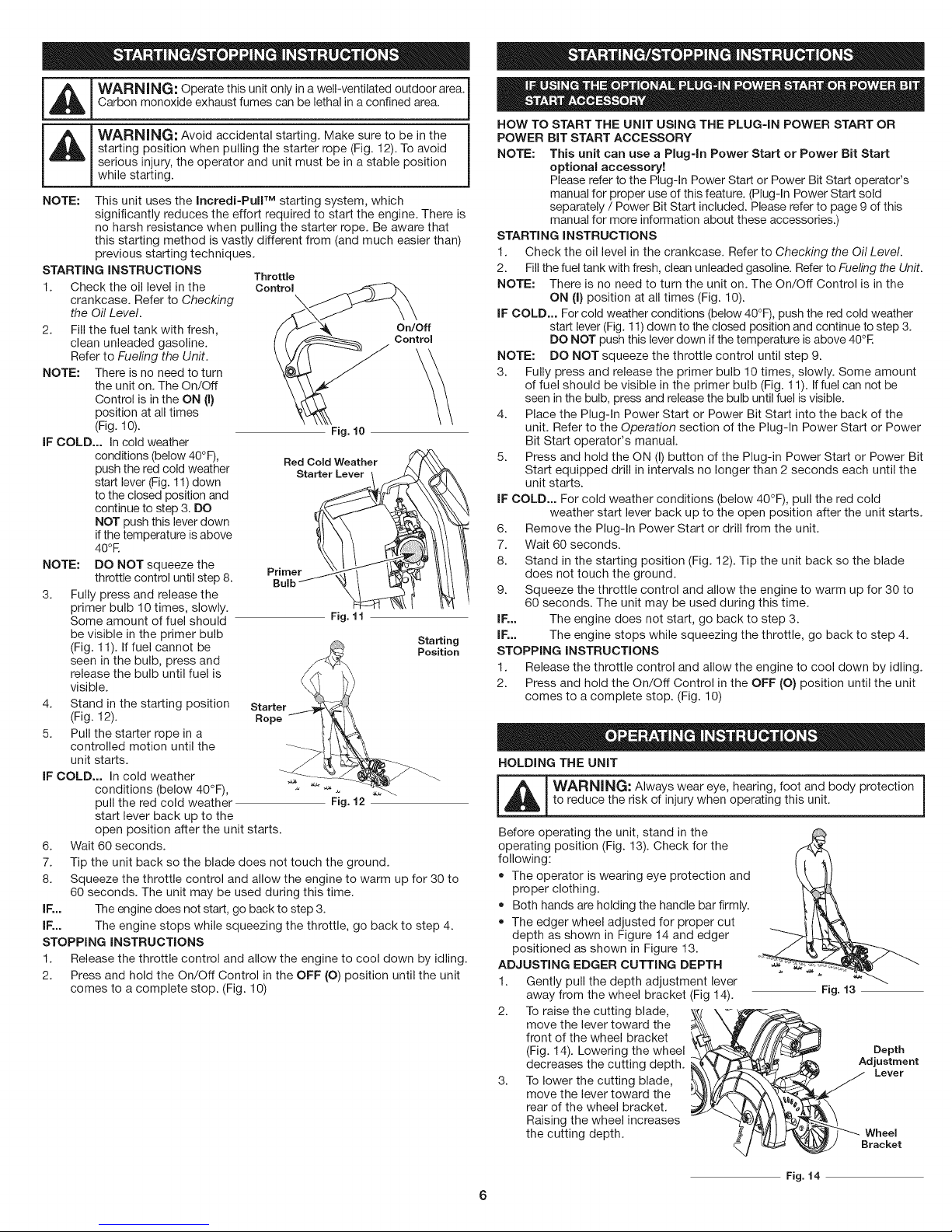
RECOMMENDED FUEL TYPE
Old fuel is the primary reason for
improper unit performance. Be
sure to use fresh, clean, unleaded
gasoline.
NOTE: Dispose of the old
NOTE: This is a four cycle
Definition of Blended Fuels oil FillPlug
Today's fuels are often a blend of
gasoline and oxygenates such as
ethanol, methanol or MTBE (ether).
Alcohol-blended fuel absorbs
water. As little as 1% water in the O-Ring
fuel can make fuel and oil separate
or form acids when stored. Use
fresh fuel (less than 30 days old), Oil Fill
when using alcohol-blended fuel. Hole
Using Blended Fuels
If choosing to use a blended fuel, Fig. 8
or its use is unavoidable, follow recommended precautions:
• Always use fresh unleaded gasoline
• Use the fuel additive STA-BIL® or an equivalent
• Drain tank and run the engine dry before storing unit
Using Fuel Additives
gasoline in accordance
with federal, state and
local regulations.
engine. In order to avoid oil Fill Hole
damage to the unit, do
not mix oil with Fig. 7
gasoline.
WARNING: Gasoline is extremely flammable. Ignited vapors
may explode. Always stop the engine and allow it to cool before
filling the fuel tank. Do not smoke while filling the tank. Keep
sparks and open flames at a distance from the area.
SERIOUS PERSONAL INJURY. Check and maintain the proper oil
level in the crankcase; it is important and cannot be
L_I_.[ WARNING: OVERFILLING OIL CRANKCASE MAY CAUSE
RECOMMENDED OiL TYPE
Using the proper type and weight of oil in the crankcase is extremely important.
Check the oil before each use and change the oil regularly. Failure to use the
correct oil, or using dirty oil, can cause premature engine wear and failure.
Use a high-quality SAE 30 weight oil of API (American Petroleum Institute)
service class SF,SG, SH.
ADDING OiL TO CRANKCASE: INITIAL USE
NOTE: This unit is shipped
The unit is supplied with one 3.04
fluid oz. (90 ml) bottle of SAE 30
SF, SG, SH oil (Fig. 6).
NOTE: Save the bottle of oil. It
1. Unscrew the top of the bottle of oil and remove the paper seal covering
2. Place unit on a flat, level surface.
3. Remove the oil fill plug from the crankcase (Fig.8).
4. Pour the entire bottle of oil into the oil fill hole (Fig. 7).
NOTE: Never add oil to the fuel or fuel tank.
5. Wipe up any oil that may have spilled and reinstall the oil fill plug.
Check oil before each use and change as needed. Refer to Checking the Oil
Level.
overemphasized. Check the oil before each use and change it as
needed. See Changing the Oil.
without oil. In order to
avoid damage to the unit,
put oil in the crankcase
before attempting to start
the unit.
can be used to measure
the correct amount
during future oil changes.
See Changing the Oil.
the opening. Replace the top. Next, cut the tip off the funnel spout (Fig. 6).
Fig.6
WARNING: Add fuel in a clean, well ventilated outdoor area. Wipe
up any spilled fuel immediately. Avoid creating a source of ignition for
spilt fuel. Do not start the engine until fuel vapors dissipate.
The use of fuel additives, such as STA-BIL® Gas Stabilizer or an equivalent, will
inhibit corrosion and minimize the formation of gum deposits. Using afuel additive
can keep fuel from forming harmful deposits in the carburetor for up to six (6)
months. Add 0.8 oz. (23 ml) of fuel additive per gallon of fuel according to the
instructions on the fuel additive container. NEVER add fuel additives directly to the
unit's gas tank.
FUELING THE UNIT
1. Remove the fuel cap (Fig. 9).
2. Place the gas container's spout into the fill hole on the fuel tank (Fig. 9)
and fill the tank.
_[_ WARNING: Remove fuel cap slowly to avoid injury from fuel
_ ARNING: DO NOT USE E85 FUEL IN THIS UNIT. It has
NOTE: Do not overfill the tank.
3. Wipe up any gasoline that
4. Reinstall the fuel cap.
5. Move the unit at least 30 ft.
5
spray. Never operate the unit without the fuel cap securely in place.
been proven that fuel containing greater than 10% ethanol will
likely damage this engine and void the warranty.
may have spilled.
(9.1 m) from the fueling
source and site before
starting the engine.
Gas Can Spout
Fig. 9
Fuel Tank
m
_L_ WARNING: Operate this unit only in a well-ventilated outdoor area. I
_ WARNING: Avoid accidental starting. Make sure to be in the
NOTE:
STARTING INSTRUCTIONS
1. Check the oil level in the
2. Fill the fuel tank with fresh,
NOTE: There is no need to turn
IF COLD... In cold weather
NOTE: DO NOT squeeze the
3. Fully press and release the
4. Stand in the starting position
5. Pull the starter rope in a
IF COLD... In cold weather
6.
7. Tip the unit back so the blade does not touch the ground.
8. Squeeze the throttle control and allow the engine to warm up for 30 to
IF... The engine does not start, go back to step 3.
IF... The engine stops while squeezing the throttle, go back to step 4.
STOPPING INSTRUCTIONS
1. Release the throttle control and allow the engine to cool down by idling.
2. Press and hold the On/Off Control in the OFF (O) position until the unit
Carbon monoxide exhaust fumes can be lethal in a confined area. j
starting position when pulling the starter rope (Fig. 12). To avoid
serious injury, the operator and unit must be in a stable position
while starting.
This unit uses the Incredi-PuIF M starting system, which
significantly reduces the effort required to start the engine. There is
no harsh resistance when pulling the starter rope. Be aware that
this starting method is vastly different from (and much easier than)
previous starting techniques.
Throttle
crankcase. Refer to Checking
the Oil Level.
clean unleaded gasoline.
Refer to Fueling the Unit.
the unit on. The On/Off
Control is in the ON (I)
position at all times
(Fig. 10).
conditions (below 40°F),
push the red cold weather
start lever (Fig. 11) down
to the closed position and
continue to step 3. DO
NOT push this lever down
if the temperature is above
40OR
throttle control until step 8.
primer bulb 10 times, slowly.
Some amount of fuel should
be visible in the primer bulb
(Fig. 11). If fuel cannot be
seen in the bulb, press and
release the bulb until fuel is
visible.
(Fig. 12).
controlled motion until the
unit starts.
conditions (below 40°F),
pull the red cold weather
start lever back up to the
open position after the unit starts.
Wait 60 seconds.
60 seconds. The unit may be used during this time.
comes to a complete stop. (Fig. 10)
Control
On/Off
Control
Fig. i0
ResdtCold Weather
Primer _
Bulb i
Fig. f I
Fig. 12
\
Starting
Position
HOW TO START THE UNIT USING THE PLUG=IN POWER START OR
POWER BiT START ACCESSORY
NOTE: This unit can use a Plug-in Power Start or Power Bit Start
]
STARTING INSTRUCTIONS
1. Check the oil level in the crankcase. Refer to Checking the Oil Level.
2. Fillthe fuel tank with fresh, clean unleaded gasoline. Refer to Fueling the Unit.
NOTE: There is no need to turn the unit on. The On/Off Control is in the
IF COLD... For cold weather conditions (below 40°F), push the red cold weather
NOTE: DO NOT squeeze the throttle control until step 9.
3. Fully press and release the primer bulb 10 times, slowly. Some amount
4. Place the Plug-In Power Start or Power Bit Start into the back of the
5. Press and hold the ON (I)button of the Plug-in Power Start or Power Bit
IF COLD... For cold weather conditions (below 40°F), pull the red cold
6. Remove the Plug-In Power Start or drill from the unit.
7. Wait 60 seconds.
8. Stand in the starting position (Fig. 12). Tip the unit back so the blade
9. Squeeze the throttle control and allow the engine to warm up for 30 to
IF... The engine does not start, go back to step 3.
IF... The engine stops while squeezing the throttle, go back to step 4.
STOPPING INSTRUCTIONS
1. Release the throttle control and allow the engine to cool down by idling.
2. Press and hold the On/Off Control in the OFF (O) position until the unit
HOLDING THE UNIT
_ ARNING: Always wear eye, hearing, foot and body protection
Before operating the unit, stand in the
operating position (Fig. 13). Check for the
following:
• The operator is wearing eye protection and
• Both hands are holding the handle bar firmly.
• The edger wheel adjusted for proper cut
ADJUSTING EDGER CUTTING DEPTH
1. Gently pull the depth adjustment lever
2. To raise the cutting blade, \\_ \- '
3. To lower the cutting blade,
optional accessory!
Please refer to the Plug-In Power Start or Power Bit Start operator's
manual for proper use of this feature. (Plug-In Power Start sold
separately / Power Bit Start included. Please refer to page 9 of this
manual for more information about these accessories.)
ON (I) position at all times (Fig. 10).
start lever (Fig. 11)down to the closed position and continue to step 3.
DO NOT push this lever down if the temperature is above 40°E
of fuel should be visible in the primer bulb (Fig. 11). If fuel can not be
seen in the bulb, press and release the bulb until fuel is visible.
unit. Refer to the Operation section of the Plug-In Power Start or Power
Bit Start operator's manual.
Start equipped drill in intervals no longer than 2 seconds each until the
unit starts.
weather start lever back up to the open position after the unit starts.
does not touch the ground.
60 seconds. The unit may be used during this time.
comes to a complete stop. (Fig. 10)
to reduce the risk of injury when operating this unit.
proper clothing.
depth as shown in Figure 14 and edger
positioned as shown in Figure 13.
away from the wheel bracket (Fig 14).
move the lever toward the
front of the wheel bracket
(Fig. 14). Lowering the wheel
decreases the cutting depth.
move the lever toward the
rear of the wheel bracket.
Raising the wheel increases
the cutting depth.
Fig. 13
Lever
2#1¢'t
Fig. f 4
TiPS FOR BEST EDGING RESULTS
• After starting the engine, keep
the unit tilted back so the blade
does not touch the ground.
Move the unit to the desired
location and slowly lower the
blade into the ground.
Do not force the edger. Edge
the first time at a lesser depth
(no more than 1/2" depth cut
per pass), then do the area
again with a deeper setting.
• Walk the edger at a slow, even
pace.
Check the blade condition (Fig. 15). As it wears it becomes smaller, thus
reducing the cutting depth performance. Replace the blade when it no
longer makes contact with the ground.
MAINTENANCE SCHEDULE
-- i
_ ARNING: To avoid serious personal injury, always turn the
Perform these required maintenance procedures at the frequency stated in
the table. These procedures should also be a part of any seasonal tune-up.
NOTE: Some maintenance procedures may require special tools or skills. If
NOTE:
NOTE:
FREQUENCY MAINTENANCE REQUIRED SEE
Every 10 hours Clean and oil air filter p. 8
After 1st 10 Change oil p. 7
hours Check rocker arm to valve clearance and adjust p. 8
Every 40 hours Change oil p. 7
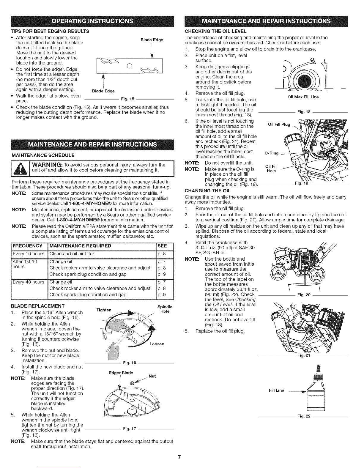
BLADE REPLACEMENT
1. Place the 5/16" Allen wrench
2. While holding the Allen
3. Remove the nut and blade.
4. Install the new blade and nut
NOTE: Make sure the blade
5. While holding the Allen
NOTE:
unit off and allow it to cool before cleaning or maintaining it.
unsure about these procedures take the unit to Sears or other qualified
service dealer. Call 1-800-4-MY-HOME® for more information.
Maintenance, replacement, or repair of the emission control devices
and system may be performed by a Sears or other qualified service
dealer. Call 1-800-4-MY-HOME® for more information.
Please read the California/EPA statement that came with the unit for
a complete listing of terms and coverage for the emissions control
devices, such as the spark arrestor, muffler, carburetor, etc.
Check spark plug condition and gap p. 9
Check rocker arm to valve clearance and adjust p. 8
Check spark plug condition and gap p. 9
in the spindle hole (Fig. 16).
wrench in place, loosen the
nut with a 15/16" wrench by
turning it counterclockwise
(Fig. 16).
Keep the nut for new blade
installation.
(Fig. 17).
edges are facing the
proper direction (Fig. 17).
The unit will not function
correctly if the edger
blade is installed
backward.
wrench inthe spindle hole,
tighten the nut by turning the
wrench clockwise until tight
(Fig. 16).
Make sure that the blade stays flat and centered against the output
shaft throughout installation.
t
Blade Edge
Fig. 15
Tighten Hole
Edger Blade
Blade Edge
O
Spindle
Fig. 16
Fig. 17
CHECKING THE OiL LEVEL
The importance of checking and maintaining the proper oil level in the
crankcase cannot be overemphasized. Check oil before each use:
1. Stop the engine and allow oil to drain into the crankcase.
2. Place unit on a flat, level
surface.
3. Keep dirt, grass clippings
and other debris out of the
engine. Clean the area
around the dipstick before
removing it.
4. Remove the oil fill plug.
5. Look into the oil fill hole, use
a flashlight if needed. The oil
should be just touching the
inner most thread (Fig. 18).
6. Ifthe oil level is not touching
the inner most thread on the
oil fill hole, add a small
amount of oil to the oil fill hole
and recheck (Fig. 21). Repeat
this procedure until the oil
level reaches the inner most O-Ring
thread on the oil fill hole.
NOTE: Do not overfill the unit.
NOTE: Make sure the O-ring is Hole
CHANGING THE OiL
Change the oil while the engine is still warm. The oil will flow freely and carry
away more impurities.
1. Remove the oil fill plug.
2. Pour the oil out of the oil fill hole and into a container by tipping the unit
3. Wipe up any oil residue on the unit and clean up any oil that may have
4. Refill the crankcase with
NOTE: Use the bottle and
5. Replace the oil fill plug.
in place on the oil fill
plug when checking and
changing the oil (Fig. 19). Fig. 19
to a vertical position (Fig. 20). Allow ample time for complete drainage.
spilled. Dispose of the oil according to federal, state and local
regulations.
3.04 fl.oz. (90 ml) of SAE 30
SF, SG, SH oil.
spout saved from initial
use to measure the
correct amount of oil.
The top of the label on
the bottle measures
approximately 3.04 fl.oz.
(90 ml) (Fig. 22). Check
the level, See Checking
the Oil Level. If the level
is low, add a small
amount of oil and
recheck. Do not overfill
(Fig. 18).
Oil Fill Plug
Oil Fill
Fill Line
Oil Max Fill Line
Fig. 18
Fig. 20
Fig. 21
Fig. 22

AiR FILTER MAINTENANCE
Cleaning the Air Filter
Air Filter Air Filter Cover Knob
Failure to maintain the air filter
properly can result in poor
performance or can cause
permanent damage to the engine.
1. Open the air filter cover.
Unscrew the knob on the left
side of the cover. Swing the
cover out (Fig. 23).
2.
Remove the air filter (Fig. 23).
3.
Wash the filter in detergent and water. Rinse the filter thoroughly and
Back Plate
Fig. 23
Hooks
allow it to dry.
4. Apply enough clean SAE 30 motor oil to lightly coat the filter.
5. Squeeze the filter to spread and remove excess oil.
6. Replace the filter (Fig. 23).
NOTE: Operating the unit without the air filter, will VOID the warranty.
7. Make sure the back plate is correctly positioned (Fig. 23).
8. Swing the air filter cover closed and tighten the knob (Fig. 23).
iDLE SPEED ADJUSTMENT
The idle speed of the engine is adjustable. An idle adjustment screw is
between the air filter cover and the engine starter housing (Fig. 24).
NOTE: Careless adjustments can seriously damage the unit. Aside from idle
speed, only a Sears or other qualified service dealer should make
carburetor adjustments.
If, after checking the fuel and cleaning the air filter, the engine still will not
idle, adjust the idle speed screw as follows:
I _i_ ! WARNING: The blade may spin during idle speed adjustments.
Wear protective clothing and observe all safety instructions toprevent serious personal injury.
1. Start the engine and let it run at a high idle for a minute to warm up.
Refer to Starting/Stopping Instructions.
2. Release the throttle lever and
let the engine idle. If the Idle Adjustment
engine stops, insert a small Screw
Phillips in between the air
filter cover and the engine
cover (Fig. 24). Turn the idle
speed screw in, clockwise,
1/8 of a turn at a time (as
needed) until the engine idles
smoothly.
NOTE: The blade should not Fig. 24
rotate when the engine
idles.
3. If the blade rotates when the engine idles, turn the idle speed screw
counterclockwise 1/8 of a turn at a time (as needed), to reduce idle
speed.
Checking the fuel, cleaning the air filter, and adjusting the idle speed should
solve most engine problems. If not and any of the following are true have the
unit serviced by a Sears or other qualified service dealer:
• the engine will not idle
the engine hesitates or stalls on acceleration
there is a loss of engine power
ROCKER ARM CLEARANCE
This requires disassembly of the engine. If unsure or unqualified to perform this,
take the unit to a Sears or other qualified service dealer.
The engine must be cold when checking or adjusting the valve clearance.
This task should be performed inside, in a clean, dust free area.
1. Remove the six (6) screws on the back of the engine cover with a Flat-
head or T-25 Torx screwdriver (Fig. 25).
2. Disconnect the spark plug wire.
3. Clean dirt from around the spark plug. Remove the spark plug from the
cylinder head by turning a 5/8 in. socket counterclockwise.
4. Remove the engine cover (Fig. 25).
5. Clean dirt from around the rocker arm cover. Remove the screw holding
the rocker arm cover with a large flat blade screwdriver or Torx T-25 bit
(Fig. 26). Remove the rocker arm cover and gasket.
6. Pull the starter rope slowly to bring the piston to the top of its travel,
(known as top dead center). Check that:
The piston isat the top of its travel. This should be done by looking into the
spark plug hole. (Fig. 26)
Both rocker arms move freely,
and both valves are closed View of the Rear Engine Cover
If these statements are not true,
repeat step 6.
7. Slide the feeler gauge between Screws
the rocker arm and the valve Screws
return spring. Measure the
clearance between the valve
stem and rocker arm (Fig. 28).
Measure both the intake and
exhaust valves.
The recommended clearance for Fig. 25
both intake and exhaust is .003 - Screw _
.006 in. (.076 = 0.152 rnm). Use a
standard automotive .005 in. Rocker Arm
0
(0.127 mm) feeler gauge. The Cover
feeler gauge should slide between
the rocker arm and valve stem Spark Plug
with a slight amount of resistance, Hole
without binding (Fig. 27 and 28).
8. If the clearance is not within
specification: Fig. 26
a. Turn the adjusting nut using a
5/16 inch (8 mm) wrench or Adjusting Nuts
nut driver (Fig. 28).
To increase clearance, turn INTAKE
the adjusting nut
counterclockwise. EXHAUST
• To decrease clearance, turn Rocker
the adjusting nut clockwise. Arms
b. Recheck both clearances,
and adjust as necessary.
9. Reinstall the rocker arm Fig. 27
cover using a new gasket.
Torque the screw to 20-30 Exhaust Rocker Arm
in'lb (2.2-3.4 N,m}. Nut __ Feeler
Adjusting ----
10. Check the spark plug and _ Gauge
Spark Plug. . . .
O003-0 006 in.
11. Replace the spark plug wire. (0.076-0.152 ram)
reinstall. See Replacing the -_ _ --
12. Reinstall the engine cover.
Check alignment of the cover
before tightening the screws. _ Valve Stem
Tighten screws. Fig. 28
REPLACING THE SPARK PLUG
Use a replacement Champion ® #RDZ4H spark plug. The correct air gap
is 0.025 in. (0.635 rnrn).
1. Stop the engine and allow it to cool. Remove the six (6) screws on the back
of the engine cover with a Flat-head or T-25 Torx screwdriver (Fig. 25).
2. Grasp the plug wire firmly and pull the cap from the spark plug.
3. Clean dirt from around the spark plug. Remove the spark plug from the
cylinder head by turning a 5/8 in. socket counterclockwise.
_, I WARNING: Do not sand blast, scrape or clean spark plug
-- i
4. Replace cracked, fouled or I I
5. Install a correctly-gapped
If using a torque wrench torque to: 0.025 in. $
110-120 in.olb. (12.3-13.5 Nora) (0.635ram} f
Do not over=tighten. Fig. 29
CLEANING
e ectrodes. Gr t n
dirty spark plug. Set the air
gap at 0.025 in. (0.635 rnrn)
using a feeler gauge (Fig. 29).
spark plug in the cylinder
head. Turn the 5/8 in. socket
clockwise until snug.
the
engine could damage the cylinder.
!
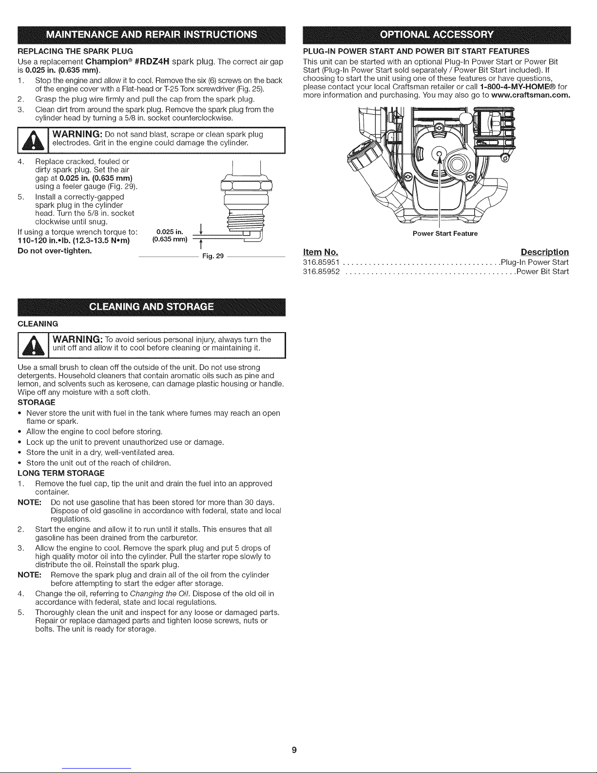
PLUG=IN POWER START AND POWER BiT START FEATURES
This unit can be started with an optional Plug-In Power Start or Power Bit
Start (Plug-In Power Start sold separately / Power Bit Start included). If
choosing to start the unit using one of these features or have questions,
please contact your local Craftsman retailer or call 1-800=4=MY-HOME® for
more information and purchasing. You may also go to www.craftsman.com.
Power Start Feature
item No. Description
316.85951 ..................................... Plug-In Power Start
316.85952 ........................................ Power Bit Start
m i_ ARNING: To avoid serious personal injury, always turn the
Use a small brush to clean off the outside of the unit. Do not use strong
detergents. Household cleaners that contain aromatic oils such as pine and
lemon, and solvents such as kerosene, can damage plastic housing or handle.
Wipe off any moisture with a soft cloth.
STORAGE
LONG TERM STORAGE
1. Remove the fuel cap, tip the unit and drain the fuel into an approved
NOTE: Do not use gasoline that has been stored for more than 30 days.
2. Start the engine and allow it to run until it stalls. This ensures that all
3. Allow the engine to cool. Remove the spark plug and put 5 drops of
NOTE: Remove the spark plug and drain all of the oil from the cylinder
4. Change the oil, referring to Changing the Oil. Dispose of the old oil in
5. Thoroughly clean the unit and inspect for any loose or damaged parts.
unit off and allow it to cool before cleaning or maintaining it.
Never store the unit with fuel in the tank where fumes may reach an open
flame or spark.
Allow the engine to cool before storing.
Lock up the unit to prevent unauthorized use or damage.
Store the unit in a dry, well-ventilated area.
Store the unit out of the reach of children.
container.
Dispose of old gasoline in accordance with federal, state and local
regulations.
gasoline has been drained from the carburetor.
high quality motor oil into the cylinder. Pull the starter rope slowly to
distribute the oil. Reinstall the spark plug.
before attempting to start the edger after storage.
accordance with federal, state and local regulations.
Repair or replace damaged parts and tighten loose screws, nuts or
bolts. The unit is ready for storage.
9

PROBLEM SOLUTION
Empty fuel tank
Fill fuel tank with fuel
Press primer bulb fully and sioWJy i 0 times
Old fuel (over 30 days)
FouJed spark plug
Cold weather start lever is in closed position
Air filter is plugged
Drain fuel tank and add fresh fuel
Replace oi Clean the SPaik Piug
Move cold weather start lever to open position
Replace or clean the air filter
Old fuel (ovei 30 daYs)Drain fuel tank and add fresh fueJ
Improper idle speed
Old fuel (over 30 days)
Blade bound With dirt or grass
Dirty air filter
Old fuel (over 30 days)
Adjust according to the Idle Speed Adjustments section
Drain fuel tank and add fresh fuel
Stop the engine and clean the blade
Clean or replace the air filter
Drain fuel tank and add fresh fuel
Fouled spark plug Replace or clean the Spark plug
h,
10
 Loading...