

Craftsman 316745200 Owner’s Manual

Operator's Manual
[RAFTSMAN.°
18-Inch Straight Shaft/31 cc/2-Cycle
GAS-POWERED BRUSHWACKER ®
Brushcutter/Trimmer
Model No.
316.74520
,_ WARNING: Before using this product, read this
OPERATOR S MANUAL PART NO. 769-00066
PRINTED IN U.S.A.
manual and follow all its Safety Rules and
Operating Instructions.
Sears, Roebuck, and Co., Hoffman Estates, IL 60179 USA
• Safety
• Assembly
• Operation
• Maintenance
• Parts List
• Espa_ol
Save this manual for future reference.
2/02
Revl

Warranty Statement
California Proposition 65 Warning
Spark Arrestor
Rules for Safe Operation
Contents of Hardware Pack
Assembly
Operation
FULL ONE-YEAR WARRANTY ON CRAFTSMAN ® GAS-POWERED BRUSHWACKER ® BRUSHCUTTER/'rRIMMER
For one year from the date of purchase, when this Craftsman Gas-Powered Brushwacker Brushcutter/Trimmer is
maintained, lubricated and tuned up according to the operating and maintenance instructions in the operator's manual,
Sears will repair, free of charge, any defect in materials or workmanship.
This warranty excludes nylon line, spark plug, air filter, and expendable parts that become worn during normal use.
If this Brushwacker Brushcutter/Trimmer is used for commercial purposes, this warranty applies for 90 days from the date
of purchase. If this Brushwacker Brushcutter/Trimmer is used for rental purposes, this warranty applies for 30 days from
the date of purchase.
This warranty applies only while this product is in use in the United States.
WARRANTY SERVICE IS AVAILABLE BY RETURNING THE BRUSHWACKER BRUSHCITTER/TRIMMER TO THE NEAR-
EST SEARS SERVICE CENTER IN THE UNITED STATES.
This warranty gives you specific legal rights, and you may also have other rights which vary from state to state.
Sears, Roebuck and Co., D/817 WA, Hoffman Estates, IL 60179
2 Maintenance 17
2 Service and Adjustments 19
2 Storage 23
3 Specifications 23
7 Troubleshooting Chart 24
8 EPA 26
12 Parts List 27
Espa_ol E1
THE ENGINE EXHAUST FROM THIS
PRODUCT CONTAINS CHEMICALS
KNOWN TO THE STATE OF CALIFORNIA
TO CAUSE CANCER, BIRTH DEFECTS
OR OTHER REPRODUCTIVE HARM.
NOTE: For users on U.S. Forest Land and in the states of California, Maine, Oregon and Washington. All U.S. Forest
Land and the state of California (Public Resources Codes 4442 and 4443), Oregon and Washington require by law that
certain internal combustion engines operated on forest brush and/or grass-covered areas be equipped with a spark
arrestor, maintained in effective working order, or the engine be constructed, equipped and maintained for the prevention
of fire. Check with your state or local authorities for regulations pertaining to these requirements. Failure to follow these
requirements could subject you to liability or a fine. This unit is factory equipped with a spark arrestor. If it requires
replacement, ask your Sears Service Center to install the Accessory Part #182747 Spark Arrestor.
SPECIAL NOTE: exposure to vibrations through prolonged use of gasoline powered hand tools could cause blood vessel
or nerve damage in the fingers, hands, and joints of people prone to circulation disorders or abnormal swelling. Prolonged
use in cold weather has been linked to blood vessel damage in otherwise healthy people. If symptoms occur such as
numbness, pain, loss of strength, change in skin color or texture, or loss of feeling in the fingers, hands or joints,
discontinue use of this tool and seek medical attention. An anti-vibration system does not guarantee the avoidance of these
problems. Users who operate power tools on a continual and regular basis must monitor closely their physical condition
and the condition of this tool.
-2-
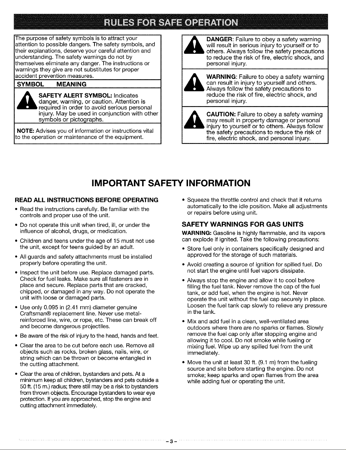
The purpose of safety symbols is to attract your
attention to possible dangers. The safety symbols, and
their explanations, deserve your careful attention and
understanding. The safety warnings do not by
themselves eliminate any danger. The instructions or
warnings they give are not substitutes for proper
accident prevention measures.
SYMBOL MEANING
,_ SAFETY ALERT SYMBOL: Indicates
NOTE: Advises you of information or instructions vital
to the operation or maintenance of the equipment.
danger, warning, or caution. Attention is
required in order to avoid serious personal
injury. May be used in conjunction with other
symbols or pictographs.
IMPORTANT SAFETY INFORMATION
DANGER: Failure to obey a safety warning
will result in serious injury to yourself or to
others. Always follow the safety precautions
to reduce the risk of fire, electric shock, and
personal injury.
WARNING: Failure to obey a safety warning
can result in injury to yourself and others.
Always follow the safety precautions to
reduce the risk of fire, electric shock, and
personal injury.
_ AUTION: Failure to obey a safety warning
may result in property damage or personal
injury to yourself or to others. Always follow
the safety precautions to reduce the risk of
fire, electric shock, and personal injury.
READ ALL INSTRUCTIONS BEFORE OPERATING
• Read the instructions carefully. Be familiar with the
controls and proper use of the unit.
• Do not operate this unit when tired, ill, or under the
influence of alcohol, drugs, or medication.
• Children and teens under the age of 15 must not use
the unit, except for teens guided by an adult.
• All guards and safety attachments must be installed
properly before operating the unit.
• Inspect the unit before use. Replace damaged parts.
Check for fuel leaks. Make sure all fasteners are in
place and secure. Replace parts that are cracked,
chipped, or damaged in any way. Do not operate the
unit with loose or damaged parts.
• Use only 0.095 in (2.41 mm) diameter genuine
Craftsman® replacement line. Never use metal-
reinforced line, wire, or rope, etc. These can break off
and become dangerous projectiles.
• Be aware of the risk of injury to the head, hands and feet.
• Clear the area to be cut before each use. Remove all
objects such as rocks, broken glass, nails, wire, or
string which can be thrown or become entangled in
the cutting attachment.
• Clear the area of children, bystanders and pets. At a
minimum keep all children, bystanders and pets outside a
50 ft. (15 m.) radius; there still may be a risk to bystanders
from thrown objects. Encourage bystanders to wear eye
protection. Ifyou are approached, stop the engine and
cutting attachment immediately.
• Squeeze the throttle control and check that it returns
automatically to the idle position. Make all adjustments
or repairs before using unit.
SAFETY WARNINGS FOR GAS UNITS
WARNING: Gasoline is highly flammable, and its vapors
can explode if ignited. Take the following precautions:
• Store fuel only in containers specifically designed and
approved for the storage of such materials.
• Avoid creating a source of ignition for spilled fuel. Do
not start the engine until fuel vapors dissipate.
• Always stop the engine and allow it to cool before
filling the fuel tank. Never remove the cap of the fuel
tank, or add fuel, when the engine is hot. Never
operate the unit without the fuel cap securely in place.
Loosen the fuel tank cap slowly to relieve any pressure
in the tank.
• Mix and add fuel in a clean, well-ventilated area
outdoors where there are no sparks or flames. Slowly
remove the fuel cap only after stopping engine and
allowing it to cool. Do not smoke while fueling or
mixing fuel. Wipe up any spilled fuel from the unit
immediately.
• Move the unit at least 30 ft. (9.1 m) from the fueling
source and site before starting the engine. Do not
smoke; keep sparks and open flames from the area
while adding fuel or operating the unit.
-3-
WHILE OPERATING
• Never start or run the unit inside a closed room or
building. Breathing exhaust fumes can kill. Operate
this unit only in a well ventilated area outdoors.
• Wear safety glasses or goggles that are marked as
meeting ANSI Z87.1 standards, and ear/hearing
protection when operating this unit. Wear a face or
dust mask if the operation is dusty. Long sleeve shirts
are recommended.
• Wear heavy, long pants, boots and gloves. Do not
wear loose clothing, jewelry, short pants, sandals, or
go barefoot. Secure hair above shoulder level.
• Adjust the assist handle to your size to provide the
best grip.
• Be sure the cutting attachment is not in contact with
anything before starting the unit.
• The cutting attachment shield must always be in place
while operating the unit as a trimmer. Do not operate
unit without both trimming lines extended, and the
proper line installed. Do not extend the trimming line
beyond the length of the shield.
• This unit has a clutch. The cutting attachment remains
stationary when the engine is idling. If it does not, have
the unit adjusted by any nonroad engine repair
establishment, individual or authorized service dealer.
• Use the unit only in daylight or good artificial light.
• Avoid accidental starting. Be inthe starting position
whenever pulling the starter rope. The operator and unit
must be in a stable position while starting. See
Stopping/Starting Instructions inthe Operation section.
• Use the right tool. Only use this tool for the purpose
intended.
• Do not overreach. Always keep proper footing and
balance.
• Always hold the unit with both hands when operating.
Keep a firm grip on both the front and rear handle or grips.
• Keep hands, face, and feet at a distance from all
moving parts. Do not touch or try to stop the cutting
attachment when it is rotating.
• Do not touch the engine or muffler. These parts get
extremely hot from operation. When turned off they
remain hot for a short time.
• Do not operate the engine faster than the speed
needed to cut, trim, or edge. Do not run the engine at
high speed when not cutting.
• Always stop the engine when cutting is delayed or
when walking from one cutting location to another.
• If you strike or become entangled with a foreign
object, stop the engine immediately and check for
damage. Do not operate before repairing damage. Do
not operate the unit with loose or damaged parts. Do
not operate unit with a bent, cracked, or dull blade.
Discard blades that are bent, warped, cracked or
broken.
• Stop and switch the engine to OFF for maintenance,
repair, or for changing the cutting attachment or other
attachments.
• Use only genuine Craftsman® replacement parts when
servicing this unit. These parts are available from your
authorized service dealer. Do not use parts,
accessories or attachments not authorized by
Craftsman for this unit. Doing so could lead to serious
injury to the user, or damage to the unit, and void your
warranty.
• Keep unit clean of vegetation and other materials.
They may become lodged between the cutting
attachment and shield.
• To reduce fire hazard, replace faulty muffler and spark
arrestor and keep the engine and muffler free from
grass, leaves, excessive grease or carbon build up.
WHILE OPERATING WITH CUTTING BLADE(S)
• Read and understand all safety warnings before
operating this unit.
• Always use the shoulder harness when using the
brush blade accessories.
• Keep the assist handle between the operator and
cutting attachment or blade at all times.
• NEVER cut with the cutting blade(s) located over 30
inches (76 cm) or more above the ground level.
• Blade thrust may occur when the spinning blade
contacts an object that it does not immediately cut.
Blade thrust can be violent enough to cause the unit
and/or operator to be propelled in any direction, and
possibly lose control of the unit. Blade thrust can
occur without warning if the blade snags, stalls, or
binds. This is more likely to occur in areas where it is
difficult to see the material being cut.
• Do not cut anything thicker than 1/2 inch with the
Craftsman 4-tooth blade, or thicker than 2 inches with
the 44-tooth saw blade, or a violent kickback could
occur.
• Do not attempt to touch or stop the blade while it is
rotating.
• A coasting blade can cause injury while it continues to
spin after the engine is stopped or the throttle trigger
is released. Maintain proper control until the blade has
completely stopped rotating.
• Do not sharpen the cutting blade(s). Sharpening a
blade can cause the blade tip to break off while in use.
This can result in severe personal injury. Replace dull
blade(s).
• Stop the engine IMMEDIATELY if you feel excessive
vibration. Vibration is a sign of trouble. Inspect
thoroughly for loose nuts, bolts, or damage before
continuing. Repair or replace affected parts as
necessary.
-4-

AFTER USE
• Clean cutting blade(s) with a household cleaner to
remove any gum buildup. Oil the blade(s) with machine
oil to prevent rust.
• Lock up and store the cutting blade in an appropriate
area to protect the blade from unauthorized use or
damage.
OTHER SAFETY WARNINGS
• Never store the unit, with fuel in the tank, inside a
building where fumes may reach an open flame or
spark.
Allow the engine to cool before storing or transporting.
Be sure to secure the unit while transporting.
Store the unit in a locked up and dry, or high and dry
place to prevent unauthorized use or damage. Keep
out of the reach of children.
Never douse or squirt the unit with water or any other
liquid. Keep handles dry, clean and free from debris.
Clean after each use. See the Maintenance and
Storage sections.
Keep these instructions. Refer to them often and use
them to instruct other users. If you loan someone this
unit, also loan them these instructions.
SAVE THESE INSTRUCTIONS
SAFETY AND INTERNATIONAL SYMBOLS
This operator's manual describes safety and international symbols and pictographs that may appear on this 3roduct.
Read the operator's manual for complete safety, assembly, operating and maintenance and repair information.
SYMBOL MEANING
• SAFETY ALERT SYMBOL
ndicates danger, warning, or caution. May be used with other symbols.
O • READ OPERATOR'S MANUAL
/ //-_
Failure to follow operating instructions and safety precautions in operator s manual can result in
serious injury. Read operator's manual before starting or operating this unit.
• WEAR EYE AND HEARING PROTECTION
WARNING: Thrown objects and loud noise can cause severe eye injury and hearing loss. Wear
eye protection meeting ANSI Z87.1-1989 standards and ear protection when operating this unit.
Use a full face shield when needec
• THROWN OBJECTS CAN CAUSE SEVERE INJURY
Do not operate unit without proper attachments and guards in place.
• KEEP CHILDREN AWAY
WARNING: Keep all bystanders, especially children and pets. at least 50 feet (15 m.) from the
operating area. Stop unit immediately if you are approachec
-5-
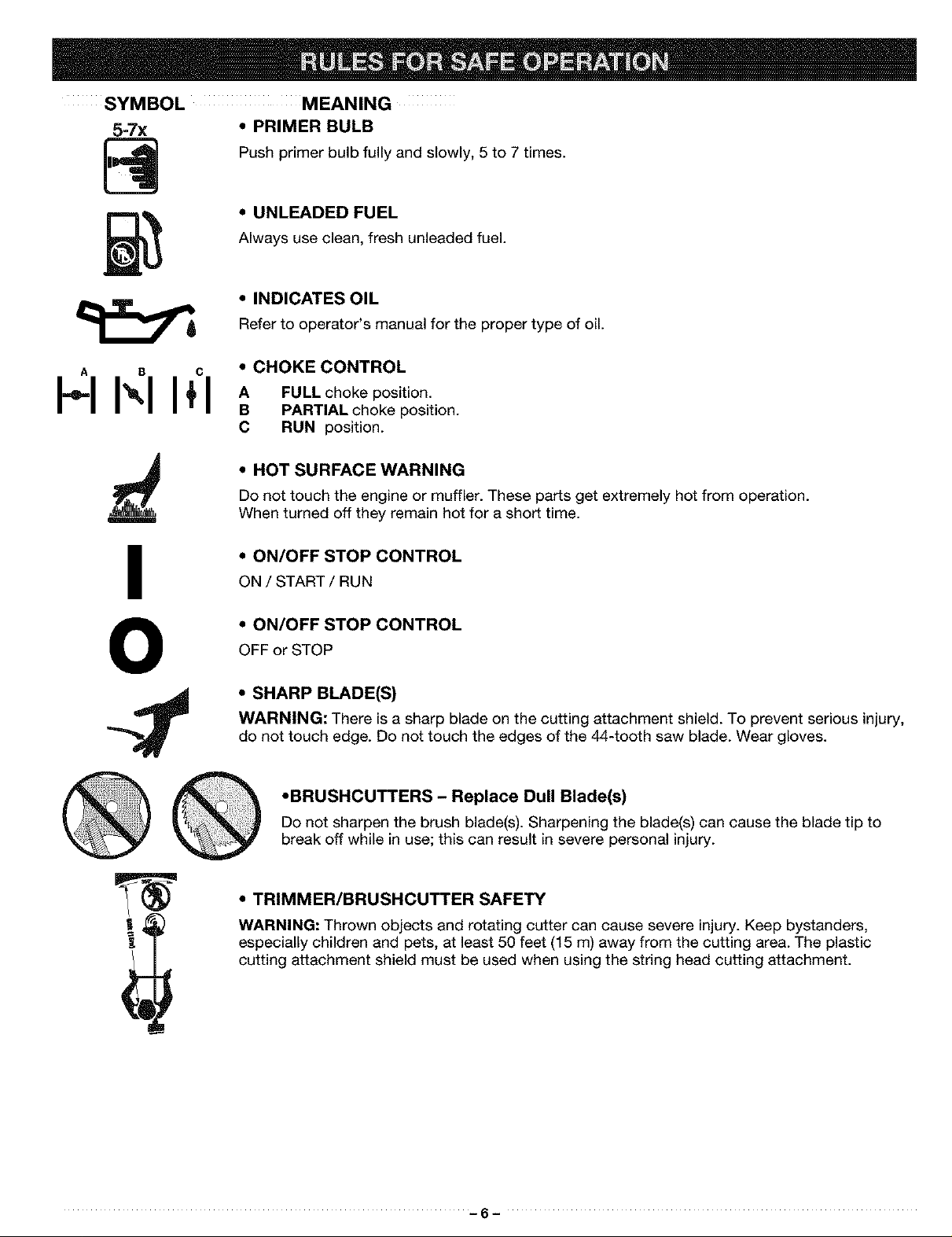
SYMBOL MEANING
• PRIMER BULB
Push primer bulb fully and slowly, 5 to 7 times.
• UNLEADED FUEL
Always use clean, fresh unleaded fuel.
• INDICATES OIL
Refer to operator's manual for the proper type of oil.
A B C • CHOKE CONTROL
B PARTIAL choke position.
C RUN position.
• HOT SURFACE WARNING
Do not touch the engine or muffler. These parts get extremely hot from operation.
When turned off they remain hot for a short time.
• ON/OFF STOP CONTROL
ON / START / RUN
• ON/OFF STOP CONTROL
OFF or STOP
• SHARP BLADE(S)
WARNING: There is a sharp blade on the cutting attachment shield. To prevent serious injury,
do not touch edge. Do not touch the edges of the 44-tooth saw blade. Wear gloves.
•BRUSHCUTTERS - Replace Dull Blade(s)
Do not sharpen the brush blade(s). Sharpening the blade(s) can cause the blade tip to
break off while in use; this can result in severe personal injury.
• TRIMMER/BRUSHCUTTER SAFETY
WARNING: Thrown objects and rotating cutter can cause severe injury. Keep bystanders,
especially children and pets, at least 50 feet (15 m) away from the cutting area. The plastic
cutting attachment shield must be used when using the string head cutting attachment.
-6-

18" Cutting
Attachment Shield
Locking
Rod Tool
Operator's Manual
4-Tooth Blade
Shoulder Harness
(3) Screws (1/4-20 x 1/2)
- for Cutting Attachment Shield
Blade Nut
Bottle of Oil
44-Tooth Blade
-7-
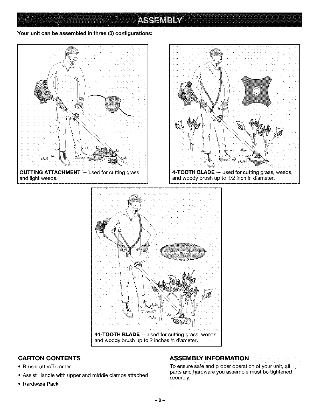
Your unit can be assembled in three (3) configurations:
]1
CUTTING ATTACHMENT -- used for cutting grass
and light weeds.
I
4-TOOTH BLADE -- used for cutting grass, weeds.
and woody brush up to 1/2 inch in diameter.
i iiii ii i i_iii i iii!I_ u
44-TOOTH BLADE -- used for cutting grass, weeds,
and woody brush up to 2 inches in diameter.
CARTON CONTENTS
• Brushcutter/Trimmer
• Assist Handle with upper and middle clamps attached
• Hardware Pack
ASSEMBLY INFORMATION
To ensure safe and proper operation of your unit, all
parts and hardware you assemble must be tightened
securely.
-8-
TOOLS REQUIRED FOR ASSEMBLY
• 5/8 inch Closed-Ended Wrench (if installing blade)
• Flat Blade Screwdriver
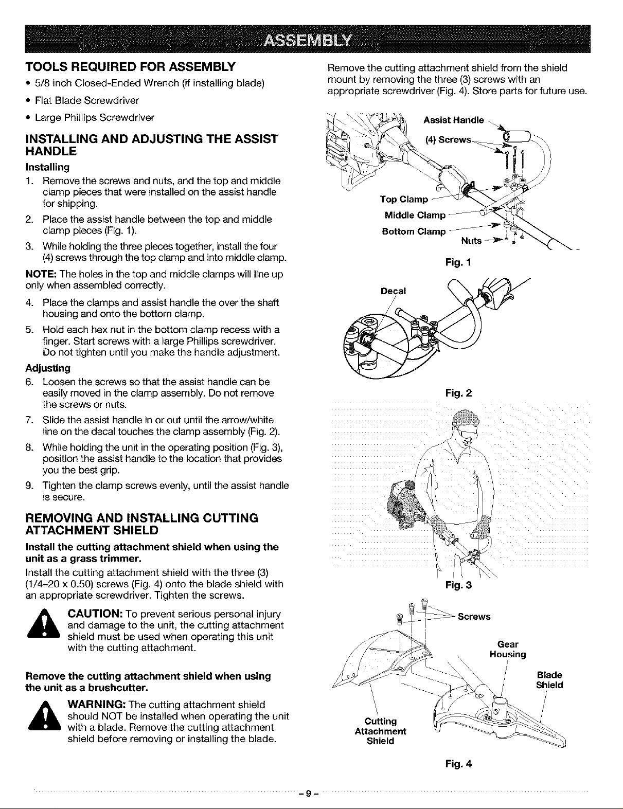
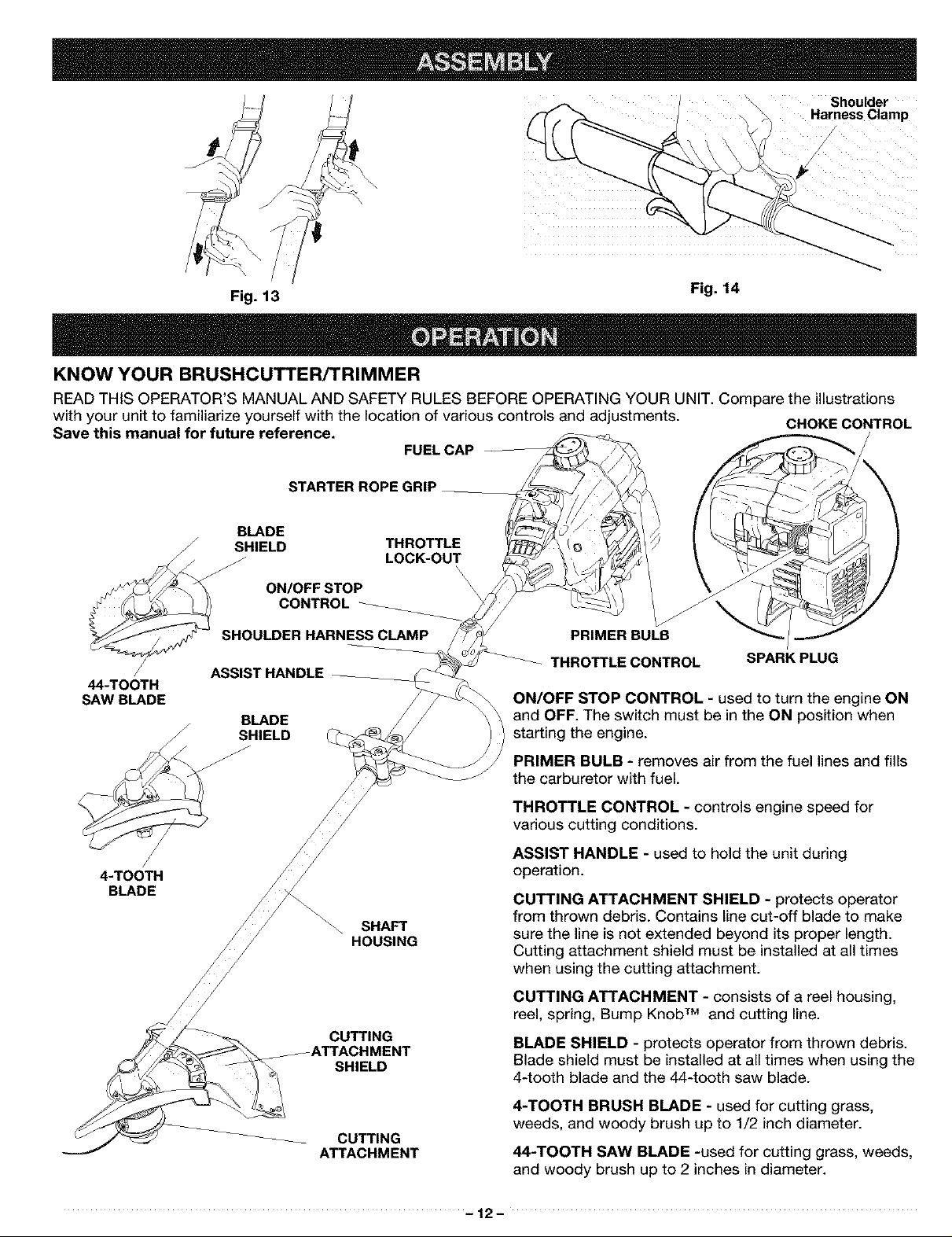
Remove the cutting attachment shield from the shield
mount by removing the three (3) screws with an
appropriate screwdriver (Fig. 4). Store parts for future use.
• Large Phillips Screwdriver
INSTALLING AND ADJUSTING THE ASSIST
HANDLE
Installing
1. Remove the screws and nuts, and the top and middle
clamp pieces that were installed on the assist handle
for shipping.
2. Place the assist handle between the top and middle
clamp pieces (Fig. 1).
3. While holding the three pieces together, install the four
(4) screws through the top clamp and into middle clamp.
NOTE: The holes in the top and middle clamps will line up
only when assembled correctly.
4. Place the clamps and assist handle the over the shaft
housing and onto the bottom clamp.
5. Hold each hex nut in the bottom clamp recess with a
finger. Start screws with a large Phillips screwdriver.
Do not tighten until you make the handle adjustment.
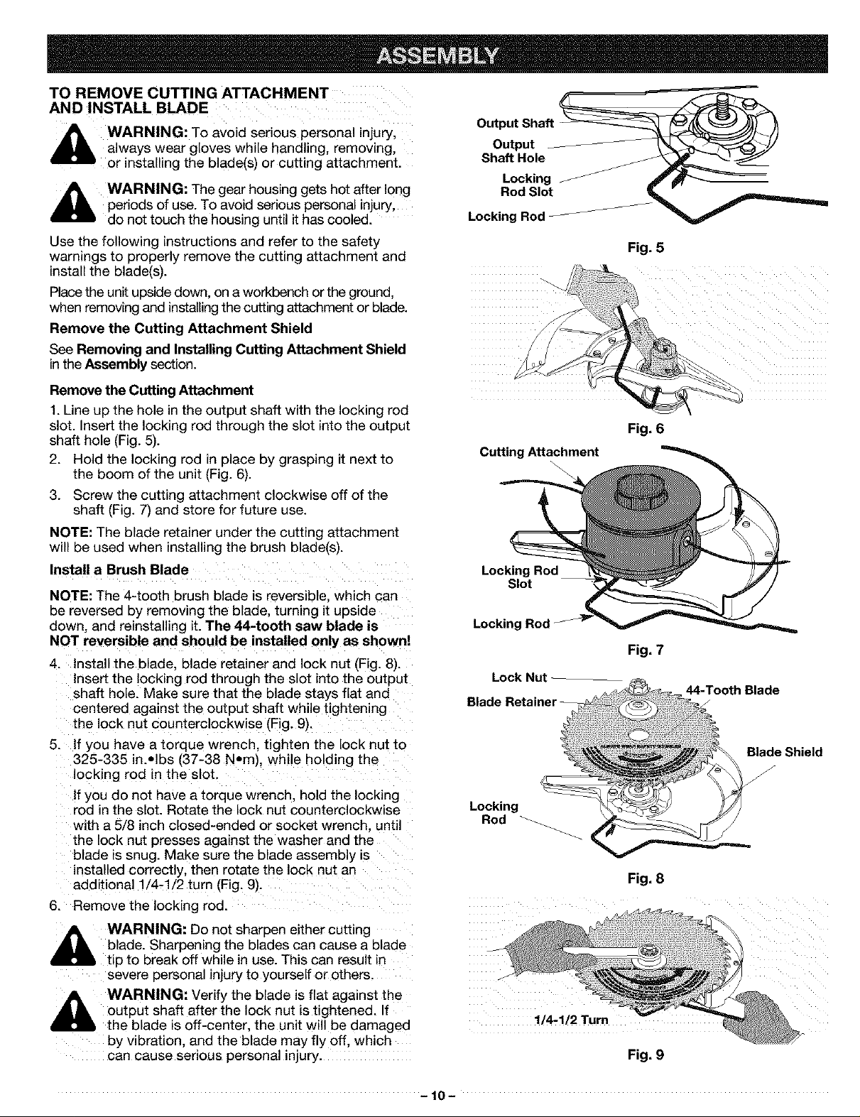
Adjusting
6. Loosen the screws so that the assist handle can be
easily moved inthe clamp assembly. Do not remove
the screws or nuts.
7. Slide the assist handle in or out until the arrow/white
line on the decal touches the clamp assembly (Fig. 2).
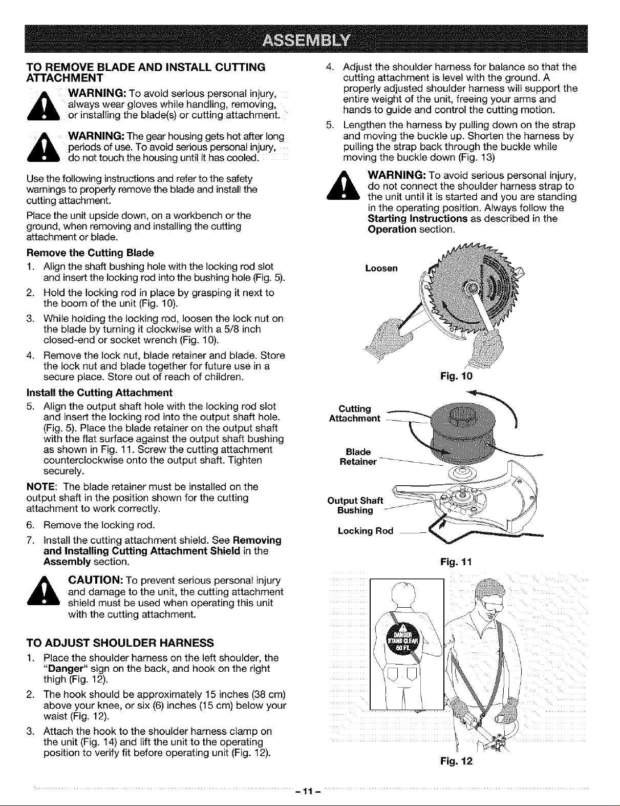
8. While holding the unit inthe operating position (Fig. 3),
position the assist handle to the location that provides
you the best grip.
9. Tighten the clamp screws evenly, until the assist handle
is secure.
Assist Handle
(4)
Top Clamp
Middle Clamp
Bottom Clamp
Nuts -_ _ ®
Fig, 1
Fig. 2
REMOVING AND INSTALLING CUTTING
ATTACHMENT SHIELD
Install the cutting attachment shield when using the
unit as a grass trimmer.
Install the cutting attachment shield with the three (3)
(1/4-20 x 0.50) screws (Fig. 4) onto the blade shield with
an appropriate screwdriver. Tighten the screws.
CAUTION: To prevent serious personal injury
and damage to the unit, the cutting attachment
shield must be used when operating this unit
with the cutting attachment.
Remove the cutting attachment shield when using
the unit as a brushcutter.
WARNING: The cutting attachment shield
should NOT be installed when operating the unit
with a blade. Remove the cutting attachment
shield before removing or installing the blade.
Fig, 3
Gear
Housing
Blade
Shield
Cutting
Attachment
Shield
Fig. 4
-9-
TO REMOVE CUTTING ATTACHMENT
AND INSTALL BLADE
A WARNING: TO avoid serious personal injuryl
,_ always wear gloves while handling, removing,
or installing the blade(s) or cutting attachment.
_!_ WARNING: The gear housing gets hot after long
periods of use. TOavoid serious personal injury,
do not touch the housing until it has cooled.
Use the following instructions and refer to the safety
warnings to properly remove the cutting attachment and
install the blade(s).
Placethe unit upside down, on a workbench or the ground,
when removing and installingthe cutting attachment or blade.
Remove the Cutting Attachment Shield
See Removing and Installing Cutting Attachment Shield
in the Assembly section.
Remove the Cutting Attachment
1. Line up the hole in the output shaft with the locking rod
slot. Insert the locking rod through the slot into the output
shaft hole (Fig. 5).
2. Hold the locking rod in place by grasping it next to
the boom of the unit (Fig. 6).
3. Screw the cutting attachment clockwise off of the
shaft (Fig. 7) and store for future use.
NOTE: The blade retainer under the cutting attachment
will be used when installing the brush blade(s).
Install a Brush Blade
NOTE: The 4-tooth brush blade is reversible, which can
be reversed by removing the blade, turning it upside
down, and reinstalling it. The 44-tooth saw blade is
NOT reversible and should be installed only as shown!
4.
Install the blade, blade retainer and lock nut (Fig. 8).
Insert the locking rod through the slot into the outout
shaft hole. Make sure that the blade stays flat and
centered against the output shaft while tightening
the lock nut counterclockwise (Fig. 9).
5. If you have a torque wrench tighten the lock nut to
325-335 in..Ibs (37-38 N.m), while holding the
locking rod in the slot.
If you do not have a torque wrench, hold the locking
rod in the slot. Rotate the lock nut counterclockwise
with a 5/8 inch closed-ended or socket wrench, until
the lock nut presses against the washer and the
blade is snug. Make sure the blade assembly is
installed correctly, then rotate the lock nut an
additional 1/4-1/2 turn (Fig. 9).
6. Remove the locking rod.
A WARNING: Do not sharpen either cutting
blade. Sharpening the blades can cause a blade
tip to break off while in use. This can result in
severe personal injury to yourself or others.
F.=.=.=.=.=.=-=-=-_
Output Shaft
Output _ /__--___)/
Shaft Hole
Locking _ J_
Rod Slot __.
Locking Rod _ V
Fig. 5
Fig. 6
Cutting Attachment
Locking Rod
Slot
Locking Rod
Fig. 7
Lock Nut
44-Tooth Blade
Blade Shield
J
Locking
Rod
Fig. 8
output shaft after the lock nut is tightened. If
WARNING: Verify the blade is flat against the
the blade is off-center, the unit will be damaged
by vibration, and the blade may fly off. which
can cause serious personal injury.
!/4-1/2 Turn
Fig. 9
-10-
TO REMOVE BLADE AND INSTALL CUTTING
ATTACHMENT
jl_ WARNING: To avoid serious personal injury,
A" always wear gloves while handling, removing,
or installing the blade(s) or cutting attachment.
A WARNING: The gear housing gets hot after long
periods of use. To avoid serious personal injury,
do not touch the housing until it has cooled.
Use the following instructions and refer to the safety
warnings to properly remove the blade and install the
cutting attachment.
Place the unit upside down, on a workbench or the
ground, when removing and installing the cutting
attachment or blade.
Remove the Cutting Blade
1. Align the shaft bushing hole with the locking rod slot
and insert the locking rod into the bushing hole (Fig. 5).
2. Hold the locking rod in place by grasping it next to
the boom of the unit (Fig. 10).
3. While holding the locking rod, loosen the lock nut on
the blade by turning it clockwise with a 5/8 inch
closed-end or socket wrench (Fig. 10).
4. Remove the lock nut, blade retainer and blade. Store
the lock nut and blade together for future use in a
secure place. Store out of reach of children.
Install the Cutting Attachment
5. Align the output shaft hole with the locking rod slot
and insert the locking rod into the output shaft hole.
(Fig. 5). Place the blade retainer on the output shaft
with the flat surface against the output shaft bushing
as shown in Fig. 11. Screw the cutting attachment
counterclockwise onto the output shaft. Tighten
securely.
NOTE: The blade retainer must be installed on the
output shaft in the position shown for the cutting
attachment to work correctly.
6. Remove the locking rod.
7. Install the cutting attachment shield. See Removing
and Installing Cutting Attachment Shield in the
Assembly section.
4.
Adjust the shoulder harness for balance so that the
cutting attachment is level with the ground. A
properly adjusted shoulder harness will support the
entire weight of the unit, freeing your arms and
hands to guide and control the cutting motion.
.
Lengthen the harness by pulling down on the strap
and moving the buckle up. Shorten the harness by
pulling the strap back through the buckle while
moving the buckle down (Fig. 13)
WARNING: To avoid serious personal injury,
do not connect the shoulder harness strap to
the unit until it is started and you are standing
in the operating position. Always follow the
Starting Instructions as described in the
Operation section.
Loosen
Fig. 10
Cutting
Attachment
Blade
Retainer
Output Shaft
Bushing
Locking Rod --
Fig. 11
CAUTION: To prevent serious personal injury
and damage to the unit, the cutting attachment
shield must be used when operating this unit
with the cutting attachment.
TO ADJUST SHOULDER HARNESS
1. Place the shoulder harness on the left shoulder, the
"Danger" sign on the back, and hook on the right
thigh (Fig. 12).
2. The hook should be approximately 15 inches (38 cm)
above your knee, or six (6) inches (15 cm) below your
waist (Fig. 12).
3. Attach the hook to the shoulder harness clamp on
the unit (Fig. 14) and lift the unit to the operating
position to verify fit before operating unit (Fig. 12).
Fig. 12
-11 -
_ ShoulderHarness Clamp
Fig. 13
Fig. 14
KNOW YOUR BRUSHCUTrER/TRIMMER
READ THIS OPERATOR'S MANUAL AND SAFETY RULES BEFORE OPERATING YOUR UNIT. Compare the illustrations
with your unit to familiarize yourself with the location of various controls and adjustments. CHOKE CONTROL
Save this manual for future reference.
FUEL CAP
STARTER ROPE GRIP ____
BLADE
SHIELD THROTTLE
___ LOCK-OUT\
ON/OFF STOP \\
CONTROL
_- SHOULDER HARN_
,/ ASSIST HANDLE
44-TOOTH
SAW BLADE
BLADE
SHIELD
J
J
ON/OFF STOP CONTROL - used to turn the engine ON
and OFF. The switch must be in the ON position when
starting the engine.
PRIMER BULB - removes air from the fuellines and fills
the carburetor with fuel.
PRIMER BULB
THROTTLE CONTROL
SPARK PLUG
4-TOOTH
BLADE
SHAFT
HOUSING
CUTTING
_ATTACHMENT
SHIELD
CUTTING
ATTACHMENT
THROTTLE CONTROL - controls engine speed for
various cutting conditions.
ASSIST HANDLE - used to hold the unit during
operation.
CUTTING ATTACHMENT SHIELD - protects operator
from thrown debris. Contains line cut-off blade to make
sure the line is not extended beyond its proper length.
Cutting attachment shield must be installed at all times
when using the cutting attachment.
CUTTING ATTACHMENT - consists of a reel housing,
reel, spring, Bump Knob TM and cutting line.
BLADE SHIELD - protects operator from thrown debris.
Blade shield must be installed at all times when using the
4-tooth blade and the 44-tooth saw blade.
4-TOOTH BRUSH BLADE - used for cutting grass,
weeds, and woody brush up to 1/2 inch diameter.
44-TOOTH SAW BLADE -used for cutting grass, weeds,
and woody brush up to 2 inches in diameter.
-12-

THIS ENGINE IS CERTIFIED TO OPERATE ON UNLEADED GAS AND OIL MIXTURE,
TO FUEL ENGINE
CAUTION: Be sure to read these instructions
carefully before attempting to start or operate
this unit. Using old or improper oil or fuel. or
improperly mixing the oil and fuel. can cause
engine damage. This type of damage will VOID
the engine warranty.
WARNING: Gasoline is extremely flammable
and its vapors can explode if they are ignited.
Always stop the engine and allow it to cool
before filling the fuel tank. Do not smoke while
filling the tank. Keep sparks and open flames
away from the area.
Recommended Oil Type
A 3.2 oz. (95ml) bottle of Craftsman® engine oil. contain-
ing fuel stabilizer, is included with your product. Crafts-
man brand oil is recommended for this outdoor power
tool. If another brand is usea. make sure it is high quality
oil, formulated for 2-cycle. air-cooled engines.
DANGER: Combustible mixture contains
petroleum distillate. Store away from heat or
open flame. Harmful or fatal if swallowed. If
swallowed, do not induce vomiting. CALL
PHYSICIAN IMMEDIATELY. Avoid prolonged
contact with skin. Wash thoroughly after
handling. Do not reuse bottle,
Use of Blended Fuels
If you choose to use a blended fuel, or if its use is un-
avoidable, the following precautions are recommended.
1. Always use fresh fuel mix.
2. Use a special additive.
3. Always agitate the fuel mix before fueling the unit,
4. Drain the tank and run the engine dry before storing
the unit.
Use of Fuel Stabilizer
If using a brand of oil other than Craftsman, use of fuel
stabilizer will inhibit corrosion and minimize the formation
of gum deposit. Add 0.8 oz. (23 ml) of stabilizer per gallon
of fuel per instructions on container. NEVER add fuel
stabilizer directly to the unit's fuel tank. Using a fuel
stabilizer can keep fuel fresh for up to six (6) months.
,_ CAUTION: For proper engine operation and
maximum reliability, pay strict attention to the
oil and fuel mixing instructions on the 2-cycle
oil Container. Use a40:1 fuel/oil ratio. Use 2-
cycle oil. Using improperly mixed fuel can
severely damage the engine.
Recommended Fuel Type
Use clean, fresh, unleaded gasoline that is less than 60
days old.
Oil and Fuel Mixing Instructions
Thoroughly mix the proper ratio of unleaded gasoline
with 2-cycle engine oil in a separate fuel can. 40:1. Do
not mix them directly in the engine fuel tank.
Use 3.2 oz. (95ml) of 2-cycle engine oil per one gallon of
unleaded gasoline to achieve a 40:1 fuel/oil ratio.
UNLEADED GAS
1 US, GALLON
(3,8 LITERS)
1 LITER
MIXING RATIO - 40:1
SEARS 2 CYCLE OIL
+ 3,2 FL, OZ,
(95 ml)
+ 25 ml
-13-
IMPORTANT
Experience indicates that alcohol blended fuels (called
gasohol or using ethanol or methanol) can attract mois-
ture which leads to separation and formation of acids
during storage. Acidic gas can damage the fuel system
of an engine while in storage. To avoid engine problems,
empty the fuel system before storage of 30 days or
longer. Drain the fuel tank, start the engine and let it run
until the fuel lines and carburetor are empty. Use fresh
fuel next season.
Never use engine or carburetor cleaner products in the
fuel tank or permanent damage may occur.
See the Storage section for additional information.
STOPPING INSTRUCTIONS
1. Run the unit at idle for a few moments to allow the
engine to cool down.
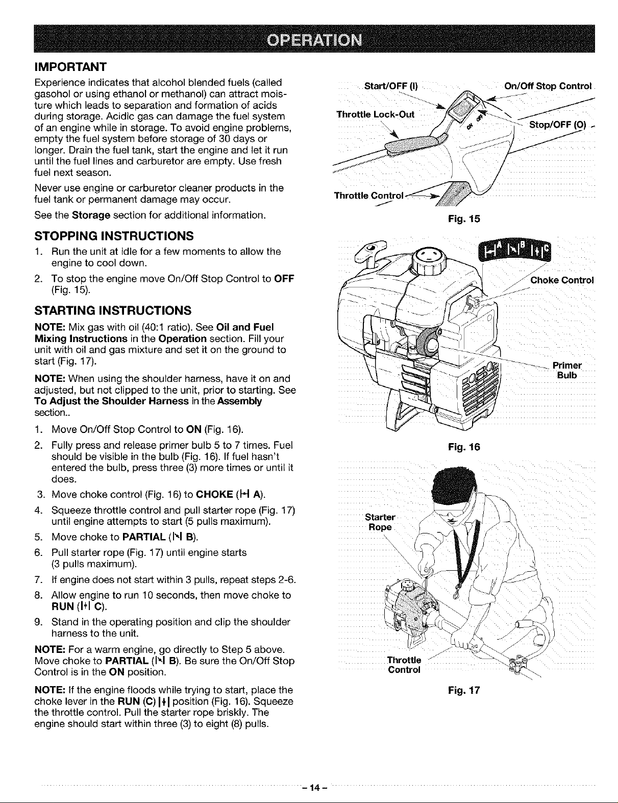
2. To stop the engine move On/Off Stop Control to OFF
(Fig. 15).
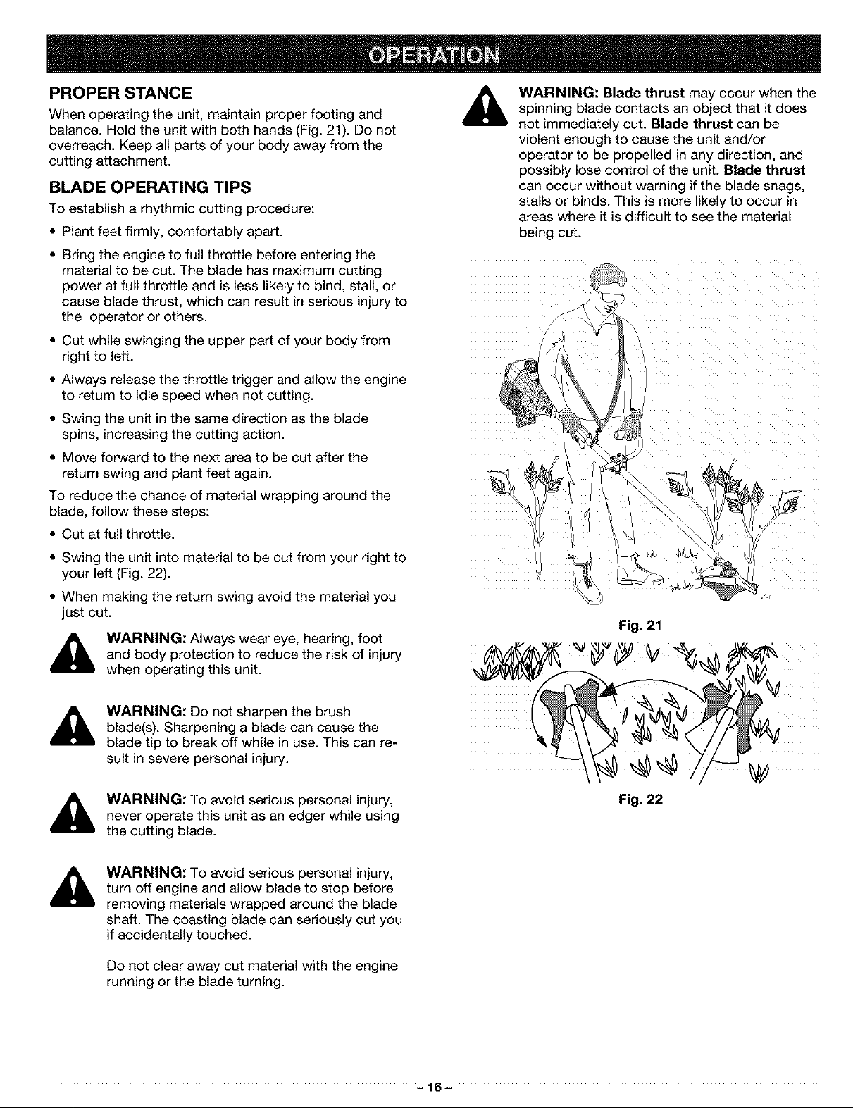
STARTING INSTRUCTIONS
NOTE: Mix gas with oil (40:1 ratio). See Oil and Fuel
Mixing Instructions in the Operation section. Fillyour
unit with oil and gas mixture and set it on the ground to
start (Fig. 17).
NOTE: When using the shoulder harness, have it on and
adjusted, but not clipped to the unit, prior to starting. See
To Adjust the Shoulder Harness in the Assembly
section..
Start/OFF (I)
Throttle Lock-Out
\
On/Off Stop Control
- Stop/OFF (O)
Fig, 15
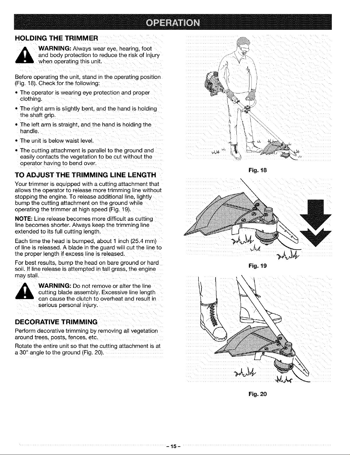
_ke Control
_ Primer
Bulb
1. Move On/Off Stop Control to ON (Fig. 16).
2. Fully press and release primer bulb 5 to 7 times. Fuel
should be visible in the bulb (Fig. 16). If fuel hasn't
entered the bulb, press three (3) more times or until it
does.
3. Move choke control (Fig. 16) to CHOKE (H A).
4. Squeeze throttle control and pull starter rope (Fig. 17)
until engine attempts to start (5 pulls maximum).
5. Move choke to PARTIAL (1_1B).
6. Pull starter rope (Fig. 17) until engine starts
(3 pulls maximum).
7. If engine does not start within 3 pulls, repeat steps 2-6.
8. Allow engine to run 10 seconds, then move choke to
RUN (1÷1C).
9. Stand in the operating position and clip the shoulder
harness to the unit.
NOTE: For a warm engine, go directly to Step 5 above.
Move choke to PARTIAL (1_1B). Be sure the On/Off Stop
Control is in the ON position.
NOTE: If the engine floods while trying to start, place the
choke lever in the RUN (C)I÷1 position (Fig. 16). Squeeze
the throttle control. Pull the starter rope briskly. The
engine should start within three (3)to eight (8) pulls.
Fig. 16
Starter
Rope
I
Throttle /
Control
Fig. 17
- 14-
HOLDING THE TRIMMER
hearing,
_ WARNING: Always wear eye, foot
Before operating the unit, stand in the operating position
(Fig. 18). Check for the following:
• The operator is wearing eye protection and Proper
clothing.
• The right arm is slightly bent, and the hand iSholding
• The left arm is straight, and the hand is holding the
• The unit is below waist level.
• The cutting attachment is parallel to the ground and
and body protection to reduce the risk of injury
when operating this unit.
the shaft grip.
handle.
easily contacts the vegetation to be cut without the
operator having to bend over.
TO ADJUST THE TRIMMING LINE LENGTH
Your trimmer is equipped with a cutting attachment that
allows the operator to release more trimming line without
stopping the engine. To release additional line, lightly
bump the cutting attachment on the ground while
operating the trimmer at high speed (Fig, !9)-
NOTE: Line release becomes more difficult as cutting
line becomes shorter. Always keep the trimming line
extended to its full cutting length.
Each time the head is bumped, about 1 inch (25.4 mm)
of line is released. A blade inthe guard will cut the line to
the proper length if excess line is released.
For best results, bump the head on bare ground or hard
soil. If line release is attempted in tall grass, the engine
may stall.
Fig. 18
%
Fig. 19
,_ WARNING: Do not remove or alter the line
,_ Cutting blade assembly. Excessive line length
can cause the clutch to overheat and result in
serious personal injury.
DECORATIVE TRIMMING
Perform decorative trimming by removing all vegetation
around trees, posts, fences, etc.
Rotate the entire unit so that the cutting attachment is at
a 30° angle to the ground (Fig. 20).
Fig. 20
-15-
PROPER STANCE
When operating the unit, maintain proper footing and
balance. Hold the unit with both hands (Fig. 21). Do not
overreach. Keep all parts of your body away from the
cutting attachment.
BLADE OPERATING TIPS
To establish a rhythmic cutting procedure:
• Plant feet firmly, comfortably apart.
• Bring the engine to full throttle before entering the
material to be cut. The blade has maximum cutting
power at full throttle and is less likely to bind, stall, or
cause blade thrust, which can result in serious injury to
the operator or others.
• Cut while swinging the upper part of your body from
right to left.
• Always release the throttle trigger and allow the engine
to return to idle speed when not cutting.
• Swing the unit in the same direction as the blade
spins, increasing the cutting action.
• Move forward to the next area to be cut after the
return swing and plant feet again.
To reduce the chance of material wrapping around the
blade, follow these steps:
• Cut at full throttle.
WARNING: Blade thrust may occur when the
spinning blade contacts an object that it does
not immediately cut. Blade thrust can be
violent enough to cause the unit and/or
operator to be propelled in any direction, and
possibly lose control of the unit. Blade thrust
can occur without warning if the blade snags,
stalls or binds. This is more likely to occur in
areas where it is difficult to see the material
being cut.
• Swing the unit into material to be cut from your right to
your left (Fig. 22).
• When making the return swing avoid the material you
just cut.
_lb WARNING: Always wear eye, hearing, foot
,_ WARNING: To avoid serious personal injury,
and body protection to reduce the risk of injury
when operating this unit.
WARNING: Do not sharpen the brush
blade(s). Sharpening a blade can cause the
blade tip to break off while in use. This can re-
sult in severe personal injury.
never operate this unit as an edger while using
the cutting blade.
WARNING: To avoid serious personal injury,
turn off engine and allow blade to stop before
removing materials wrapped around the blade
shaft. The coasting blade can seriously cut you
if accidentally touched.
Do not clear away cut material with the engine
running or the blade turning.
Fig. 21
Fig. 22
-16-
MAINTENANCE SCHEDULE
These required maintenance procedures should be
performed at the frequency stated in the table. They
should also be included as part of any seasonal tune-up.
NOTE: Some maintenance procedures may require
'_ k maintenance or repairs with unit running.
special tools or skills. If you are unsure about
these procedures take your unit to any nonroad
engine repair establishment, individual or
authorized service dealer.
I WARNING: To prevent serious injury, never do I
Always do maintenance and repairs on a cool
unit. Disconnect spark plug wire to ensure the
unit will not start.
I
NOTE: Maintenance, replacement, or repair of the emission
control devices and system may be performed by
any nonroad engine repair establishment, individual
or authorized service dealer.
In order to assure peak performance of your engine,
inspection of the engine exhaust port may be necessary
after 50 hours of operation, if you notice lost RPM, poor
performance or general lack of acceleration, this service
may be required. If you feel your engine is need of this
inspection, refer service to any nonroad engine repair
establishment, individual or authorized service dealer for
repair. DO NOT attempt to perform this process yourself
as engine damage may result from contaminants
involved in the cleaning process for the port.
FREQUENCY MAINTENANCE REQUIRED REFER TO:
Before Starting Engine Check for loose or damaged parts.
Every 10 Hours Clean and re-oil air filter. Page 17
Every 25 Hours Check spark arrestor and clean. Page 22
Every 50 Hours Inspect exhaust port and spark arrestor screen for clogging Page 22
GENERAL RECOMMENDATIONS
WARNING: To prevent serious injury, never
perform maintenance on the unit while it is
running. Shut off the unit and allow it to cool
down before doing any maintenance.
Disconnect the spark plug wire to prevent the
Unit from starting.
The warranty on this line trimmer does not cover items
that have been subjected to operator abuse or
negligence. To receive full value from the warranty, the
operator must maintain the unit as instructed in this
operator's manua!.
These required maintenance procedures should be
performed at the frequency stated in the table. They
should also be included as part of any seasonal tune-up.
CHECK FOR DAMAGED/WORN PARTS
Inspect the unit for any worn or damaged parts. Repair
or replace damaged parts before operating.
CHECK FOR LOOSE FASTENER PARTS
• Cutting Attachment
• Assist Handle Hex Nuts/Screws
• Cutting Attachment Shield Screws
• Spark Plug Wire
Fill fuel tank with correct oil and fuel mixture. Page 13
Check spark plug condition and gap. Page 18
or obstruction to assure maximum performance levels.
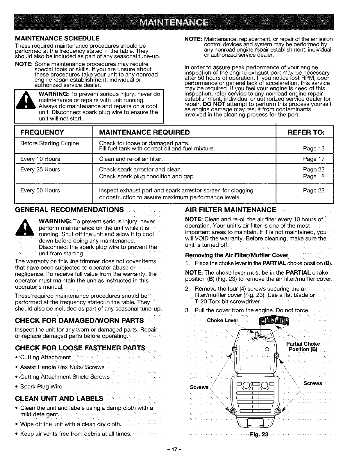
AIR FILTER MAINTENANCE
NOTE: Clean and re-oil the air filter every 10 hours of
operation. Your unit's air filter is one of the most
important areas to maintain. If it is not maintained, you
will VOID the warranty. Before cleaning, make sure the
unit is turned off.
Removing the Air Filter/Muffler Cover
1. Place the choke lever in the PARTIAL choke position (B).
NOTE: The choke lever must be in the PARTIAL choke
position (B) (Fig. 23) to remove the air -'liter/muffler cover.
2. Remove the four (4) screws securing the air
filter/muffler cover (Fig. 23). Use a flat blade or
T-20 Torx bit screwdriver.
3. Pull the cover from the engine. Do not force.
Choke Lever
Partial Choke
O Position (B]
Screws _0_0_ Screws
CLEAN UNIT AND LABELS
• Clean the unit and label s using a damp cloth with a
mild detergent.
• Wipe off the unit with a clean dry cloth.
• Keep air vents free from debris at all times.
Fig. 23
-17-
 Loading...