

Craftsman 316292650 Owner’s Manual

Operator's Manual
4-Cycle Garden
MiNi TILLER
Model No. 316.292650
CAUTION: Before using
this product, read this
manual and follow all
safety rules and operating
instructions.
Sears, Roebuck and Co., Hoffman Estates, IL 60179, U.S.A.
Visit our website: www.sears.com/craftsman
• SAFETY
ASSEMBLY
OPERATION
MAINTENANCE
PARTS LIST
• ESPANOL, R E1
769-04601 P00
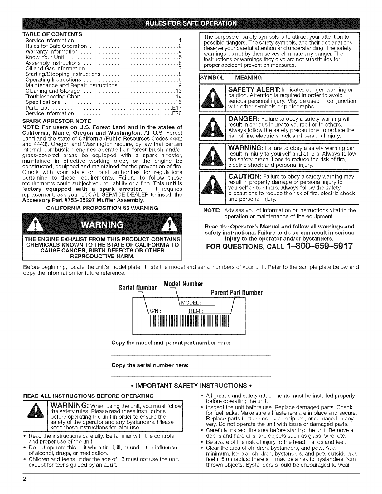
TABLE OF CONTENTS
Service Information ................................. 1
Rules for Safe Operation ............................. 2
Warranty information ................................ 4
Know Your Unit .................................... 5
Assembly instructions ............................... 6
Oil and Gas Information .............................. 7
Starting/Stopping Instructions ......................... 8
Operating instructions ............................... 9
Maintenance and Repair Instructions ................... 9
Cleaning and Storage .............................. 13
Troubleshooting Chart .............................. 14
Specifications .................................... 15
Parts List ....................................... E17
Service Information ............................... E20
SPARK ARRESTOR NOTE
NOTE: For users on U.S. Forest Land and in the states of
California, Maine, Oregon and Washington. All U.S. Forest
Land and the state of California (Public Resources Codes 4442
and 4443), Oregon and Washington require, by law that certain
internal combustion engines operated on forest brush and/or
grass-covered areas be equipped with a spark arrestor,
maintained in effective working order, or the engine be
constructed, equipped and maintained for the prevention of fire.
Check with your state or local authorities for regulations
pertaining to these requirements. Failure to follow these
requirements could subject you to liability or a fine. This unit is
factory equipped with a spark arrestor. If it requires
replacement, ask your LOCAL SERVICE DEALER to install the
Accessory Part #753-05297 Muffler Assembly.
CALiFORNiA PROPOSiTiON 65 WARNING
THE ENGINE EXHAUST FROM THIS PRODUCT CONTAINS
CHEMICALS KNOWN TO THE STATE OF CALiFORNiA TO
CAUSE CANCER, BIRTH DEFECTS OR OTHER
REPRODUCTIVE HARM.
The purpose of safety symbols isto attract your attention to
possible dangers. The safety symbols, and their explanations,
deserve your careful attention and understanding. The safety
warnings do not by themselves eliminate any danger. The
instructions or warnings they give are not substitutes for
proper accident prevention measures.
SYMBOL MEANING
SAFETY ALERT: Indicates danger, warning or
caution. Attention is required in order to avoid
,_ erious personal injury. May be used in conjunction
with other symbols or pictographs.
DANGER: Failure to obey a safety warning will
result in serious injury to yourself or to others.
Always follow the safety precautions to reduce the
risk of fire, electric shock and personal injury.
WARNING: Failure to obey a safety warning can
result in injury to yourself and others. Always follow
the safety precautions to reduce the risk of fire,
electric shock and personal injury.
CAUTION: Failure to obey a safety warning may
result in property damage or personal injury to
yourself or to others. Always follow the safety
precautions to reduce the risk of fire, electric shock
and personal injury.
NOTE: Advises you of information or instructions vital to the
operation or maintenance of the equipment.
Read the Operator's Manual and follow all warnings and
safety instructions. Failure to do so can result in serious
injury to the operator and/or bystanders.
FOR QUESTIONS, CALL 1-800-659-5917
Before beginning, locate the unit's model plate. It lists the model and serial numbers of your unit. Refer to the sample plate below and
copy the information for future reference.
Model Number
Parent Part Number
\MODEL: /
ITEM : l
Copy the model and parent part number here:
Copy the serial number here:
= IMPORTANT SAFETY INSTRUCTIONS =
READ ALL iNSTRUCTiONS BEFORE OPERATING
the safety rules. Please read these instructions
before operating the unit in order to ensure the
WARNING: When using the unit, you must follow
safety of the operator and any bystanders. Please
keep these instructions for later use.
* Read the instructions carefully. Be familiar with the controls
and proper use of the unit.
* Do not operate this unit when tired, i11,or under the influence
of alcohol, drugs, or medication.
* Children and teens under the age of 15 must not use the unit,
except for teens guided by an adult.
• All guards and safety attachments must be installed properly
before operating the unit.
Inspect the unit before use. Replace damaged parts. Check
for fuel leaks. Make sure all fasteners are in place and secure.
Replace parts that are cracked, chipped, or damaged in any
way. Do not operate the unit with loose or damaged parts.
Carefully inspect the area before starting the unit. Remove all
debris and hard or sharp objects such as glass, wire, etc.
Be aware of the risk of injury to the head, hands and feet.
Clear the area of children, bystanders, and pets. At a
minimum, keep all children, bystanders, and pets outside a 50
feet (15 m) radius; there still may be a risk to bystanders from
thrown objects. Bystanders should be encouraged to wear
eyeprotection.Ifyouareapproached,stoptheunit • Usetherighttool.Onlyusethistoolforthepurposeintended.
immediately.
Squeezethethrottlecontrolandcheckthatitreturnsauto-
maticallytotheidleposition.Makealladjustmentsorrepairs
beforeusingunit.
SAFETYWARNINGSFORGASUNITS
I _hb IWARN'NG-" Gas°line is highly flammable, andits I
* Store fuel only in containers specifically designed and
approved for the storage of such materials.
* Avoid creating a source of ignition for spilled fuel. Do not start
the engine until fuel vapors dissipate.
* Always stop the engine and allow it to cool before filling the
fuel tank. Never remove the cap of the fuel tank, or add fuel,
when the engine is hot. Never operate the unit without the fuel
cap securely in place. Loosen the fuel tank cap slowly to
relieve any pressure in the tank.
* Add fuel in a clean, well-ventilated outdoor area where there
are no sparks or flames. Slowly remove the fuel cap only after
stopping engine. Do not smoke while fueling or mixing fuel.
Wipe up any spilled fuel from the unit immediately. Always
wipe unit dry before using.
o Move the unit at least 30 feet (9.1 m) from the fueling source
and site before starting the engine. Do not smoke or allow
sparks and open flames near the area while adding fuel or
operating the unit.
WHILE OPERATING
, Never start or run the unit inside a closed room or building.
Breathing exhaust fumes can kill. Operate this unit only in a
well ventilated outdoor area.
Wear safety glasses or goggles that meet ANSI Z87.1-1989
standards and are marked as such. Wear ear/hearing protection
when operating this unit. Wear a face or dust mask if the
operation is dusty.
Wear heavy, long pants, boots, gloves and a long-sleeved shirt.
Do not wear loose clothing, jewelry, short pants, sandals or go
barefoot. Secure hair above shoulder level.
This unit has a clutch. The tines remain stationary when the
engine is idling. If they do not, have the unit adjusted by an
authorized service technician.
Be sure the tines are not in contact with anything before
starting the unit.
Use the unit only in daylight or good artificial light.
Avoid accidental starting. Be inthe starting position whenever
pulling the starter rope. The operator and unit must be in astable
position while starting. See Starting/Stopping Instructions.
vapors can explode if ignited. Take the following
precautions:
Use extreme caution when reversing or pulling the unit towards you.
Do not overreach. Always keep proper footing and balance.
Take extra care when working on steep slopes or inclines.
Always hold the unit with both hands when operating. Keep a
firm grip on the grips.
Keep hands, face, and feet at a distance from all moving parts.
Do not touch or try to stop the tines when they are rotating.
Do not touch the engine or muffler. These parts get extremely
hot from operation, even after the unit isturned off.
Do not operate the engine faster than the speed needed to
cultivate. Do not run the engine at high speed when you are
not cultivating.
Always stop the engine when cultivating is delayed or when
walking from one cultivating location to another.
If you strike or become entangled with a foreign object, stop
the engine immediately and check for damage. Do not
operate before repairing damage. Do not operate the unit
with loose or damaged parts.
Stop the unit, switch the engine to off, and disconnect the
spark plug for maintenance or repair.
Use only original equipment manufacturer replacement parts
and accessories for this unit. These are available from your
authorized service dealer. Use of any unauthorized parts or
accessories could lead to serious injury to the user, or
damage to the unit, and void your warranty.
Keep unit clean of vegetation and other materials. They may
become lodged between the tines and guard.
To reduce fire hazard, replace faulty muffler and spark
arrestor, keep the engine and muffler free from grass, leaves,
excessive grease or carbon build up.
AFTER USE
Clean tines with a household cleaner to remove any gum
buildup. Oil the tines with machine oil to prevent rust.
OTHER SAFETY WARNINGS
Never store a fueled unit inside a building where fumes may
reach an open flame or spark.
* Allow the engine to cool before storing or transporting. Be sure
to secure the unit while transporting.
* Store the unit in a dry area, locked up or up high to prevent
unauthorized use or damage, out of the reach of children.
* Never douse or squirt the unit with water or any other liquid.
Keep handles dry, clean and free from debris. Clean after each
use, see Cleaning and Storage instructions.
o Keep these instructions. Refer to them often and use them to
instruct other users. If you loan someone this unit, also loan
them these instructions.
SAVE THESE INSTRUCTIONS
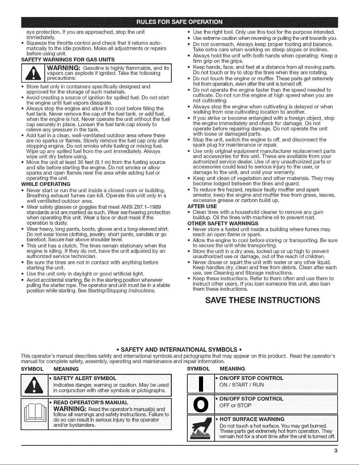
• SAFETY AND INTERNATIONAL SYMBOLS •
This operator's manual describes safety and international symbols and pictographs that may appear on this product. Read the operator's
manual for complete safety, assembly, operating and maintenance and repair information.
SYMBOL MEANING SYMBOL MEANING
A • SAFETY ALERT SYMBOL
AL I Indicates danger, warning or caution. May be used
I in conjunction with other symbols or pictographs.
WARNING: Read the operator'smanual(s)and
follow all warnings and safety instructions. Failure to
do so can result in serious injury to the operator
o READ OPERATOR'S MANUAL
and/or bystanders.
I oON/OFF STOP CONTROL
ON/START/RUN
,,ON/OFFoFFor STopSTOPCONTROL
• HOT SURFACE WARNING
Do not toUch ahot surfacel Youmay get burned.
These parts get extremely hot from operation. They
remain hot fora short time after the unit is turned off.
• UNLEADED FUEL
• WEAR EYE AND HEARING PROTECTION I
WARNING: Thrown objects and loud noise I
'_1 Always use ciean fresh unleaded fue I
• OIL
Jl Refertooperatorsmanua forthepr0pertypeofo.
WARNING: KeeP all bystanders, eSpecially
A • KEEP BYSTANDERS AWAY
children and pets, at least 50 feet (!5 m)from the
operating area.
•THROWN OBJECTS AND ROTATING CUTTER
CAN CAUSE SEVERE INJURY I
1 2 3I" CHOKE CONTROL
H N 1. : FULLchokeposition
WARNING: Do not operate without the cutting
attachment shield in placel Keep away from the I
rotat ng cutt ng attachment. J
CRAFTSMAN TWO YEAR LIMITED WARRANTY
When operated and maintained according to all supplied instructions, if this Craftsman product fails due to a defect in material or
workmanship within two years from the date or purchase, take it to any Sears or other authorized Craftsman location in the United States
for free repair. Call 1-800-4-MY-HOME® for the nearest authorized location.
This warranty applies for only 90 days from the date of purchase if this product is ever used for commercial or rental purposes.
This warranty covers ONLY defects in material and workmanship. Sears will NOT pay for:
• Expendable items that become worn during normal use, including but not limited to blades, tines, or belts.
• Tire or wheel replacement or repair resulting from normal wear, accident, or improper operation or maintenance.
• Repairs necessary because of operator abuse, including but not limited to damage caused by impacting objects that bend the frame
or motor crankshaft.
• Repairs necessary because of operator negligence, including but not limited to, electrical and mechanical damage caused by improper
storage, or failure to maintain the equipment according to the instructionscontained in the operator's manual.
• Repairs necessary due to improper fuel mixture, contaminated or stale fuel.
• Normal deterioration and wear of the exterior finishes, or product label replacement.
This warranty applies only while this product is within the United States. This warranty gives you specific legal rights, and you may also
have other rights which vary from state to state.
Sears, Roebuck and Co., Hoffman Estates, IL 60179
can cause severe eye injury and hearing loss. I
Wear eye protection meeting ANSI Z87.1-1989 I
standards and ear protection when operating this I
unit. Use a full face shield when needed. J
2. PARTIAL choke position
3. = RUN choke post on
I MINI TILLERS - ROTATING TINES I
CAN CAUSE SEVERE INJURY I
WARNING: Stop the engine and allow the tines I
to stop before installing or removing tines, or I
before cleaning or performing any maintenance. I
Keep hands and feet away from rotating tines. J
Repair Protection Agreements
Congratulations on making a smart purchase. Your new Craftsman® product is designed and manufactured for years of dependable
operation. But like all products, it may require repair from time to time. That's when having a Repair Protection Agreement can save
you money and aggravation.
Here's what the Repair Protection Agreement* includes:
[] Expert service by our 10,000 professional repair specialists
[] Unlimited service and no charge for parts and labor on all covered repairs
[] Product replacement up to $1500 if your covered product can't be fixed
[] Discount of 10% from regular price of service and related installed parts not covered by the agreement; also, 10% off regular
price of preventive maintenance check
[] Fast help by phone - we call it Rapid Resolution - phone support from a Sears representative. Think of us as a"talking owner's manual."
Once you purchase the Repair Protection Agreement, a simple phone call is all that it takes for you to schedule service. You can call
anytime day or night, or schedule a service appointment online.
The Repair Protection Agreement is a risk-free purchase. If you cancel for any reason during the product warranty period, we will
provide a full refund. Or, a prorated refund any time after the product warranty period expires. Purchase your Repair Protection
Agreement today!
Some limitations and exclusions apply. For prices and additional information in the U.S.A. call 1=800=827=6655.
*Coverage in Canada varies on some items. For full details call Sears Canada at 1=800=361=6665.
Sears Installation Service
For Sears professional installation of home appliances, garage door openers, water heaters, and other major home items, in the U.S.A.
or Canada call 1=800=4=MY=HOME ®.
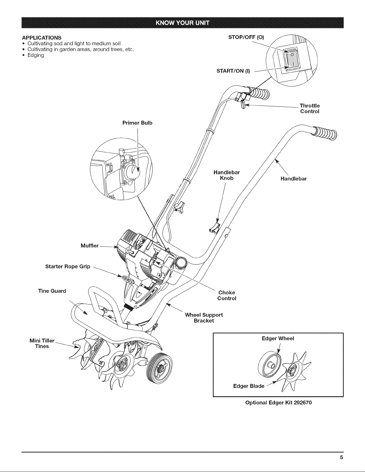
APPLICATIONS
• Cultivatingsodandlighttomediumsoil
• Cultivatingingardenareas,aroundtrees,etc.
• Edging
Primer Bulb
STOP/OFF (0}
START/ON (I)
Handlebar
Knob
Throttle
Control
Handlebar
Starter Rope Grip
Tine Guard
Mini Tiller
Tines
Muffler
Choke
Control
Wheel Support
Bracket
Edger Wheel
Edger Bla__
Optional Edger Kit 292670
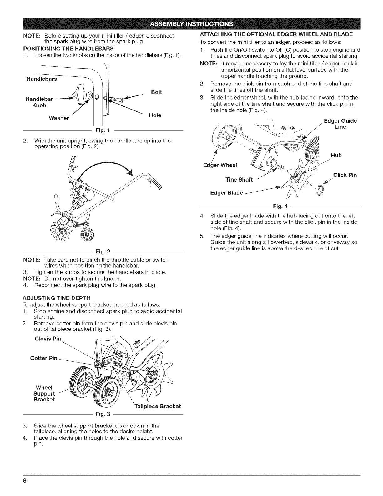
NOTE:Beforesettingupyourminitiller/ edger, disconnect
the spark plug wire from the spark plug.
POSiTiONiNG THE HANDLEBARS
1. Loosen the two knobs on the inside of the handlebars (Fig. 1).
Handlebars
Bolt
Handlebar
Knob
Washer
Fig. 1
2. With the unit upright, swing the handlebars up into the
operating position (Fig. 2).
Fig. 2
NOTE: Take care not to pinch the throttle cable or switch
wires when positioning the handlebar.
3. Tighten the knobs to secure the handlebars in place.
NOTE: Do not over-tighten the knobs.
4. Reconnect the spark plug wire to the spark plug.
Hole
ATTACHING THE OPTIONAL EDGER WHEEL AND BLADE
To convert the mini tiller to an edger, proceed as follows:
1. Push the On/Off switch to Off (O) position to stop engine and
tines and disconnect spark plug to avoid accidental starting.
NOTE: It may be necessary to lay the mini tiller / edger back in
a horizontal position on a flat level surface with the
upper handle touching the ground.
2. Remove the click pin from each end of the tine shaft and
slide the tines off the shaft.
3. Slide the edger wheel, with the hub facing inward, onto the
right side of the tine shaft and secure with the click pin in
the inside hole (Fig. 4).
Edger Guide
Line
Edg_eerWheel Hub
Click Pin
Tine Shaft
Edger Blade _
Fig. 4
4. Slide the edger blade with the hub facing out onto the left
side of tine shaft and secure with the click pin in the inside
hole (Fig. 4).
5. The edger guide line indicates where cutting will occur.
Guide the unit along a flowerbed, sidewalk, or driveway so
the edger guide line is above the desired line of cut.
ADJUSTING TINE DEPTH
Toadjust the wheel support bracket proceed as follows:
1. Stop engine and disconnect spark plug to avoid accidental
starting.
2. Remove cotter pin from the clevis pin and slide clevis pin
out of tailpiece bracket (Fig. 3).
Clevis Pin
Cotter Pin
Wheel
Support
Bracket
Tailpiece Bracket
Fig. 3
3. Slide the wheel support bracket up or down in the
tailpiece, aligning the holes to the desire height.
4. Place the clevis pin through the hole and secure with cotter
pin.
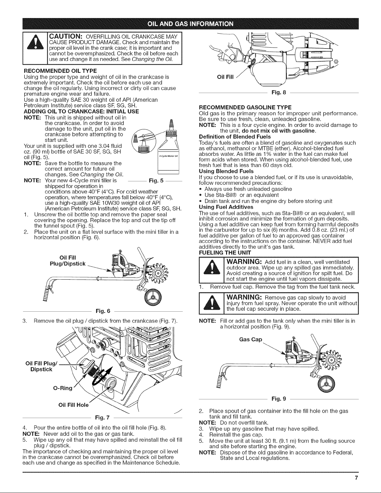
CAUTION: OVERFiLLiNG OiL CRANKCASE MAY
CAUSE PRODUCT DAMAGE. Check and maintain the
proper oil level in the crank case; it is important and
cannot be overemphasized. Check the oil before each
use and change it as needed. See Changing the Oil.
RECOMMENDED OIL TYPE
Using the proper type and weight of oil in the crankcase is
extremely important. Check the oil before each use and
change the oil regularly. Using incorrect or dirty oil can cause
premature engine wear and failure.
Use a high-quality SAE 30 weight oil of API (American
Petroleum institute) service class SF,SG, SH.
ADDING OiL TO CRANKCASE: INITIAL USE
NOTE: This unit is shipped without oil in
Your unit is supplied with one 3.04 fluid
oz. (90 ml) bottle of SAE 30 SF, SG, SH
oil (Fig. 5).
NOTE: Save the bottle to measure the
NOTE: Your new 4-Cycle mini tiller is
1.
2.
the crankcase, in order to avoid
damage to the unit, put oil in the
crankcase before attempting to
start unit.
correct amount for future oil
changes. See Changing the Oil.
Fig. 5
shipped for operation in
conditions above 40°F (4°C). For cold weather
operation, where temperatures fall below 40°F (4°C),
use a high-quality SAE 10W30 weight oil of API
(American Petroleum Institute) service class SF,SG, SH.
Unscrew the oil bottle top and remove the paper seal
covering the opening. Replace the top and cut the tip off
the funnel spout (Fig. 5).
Place the unit on a flat level surface with the mini tiller in a
horizontal position (Fig. 6).
@
Oil Fill
Fig. 8
RECOMMENDED GASOLINE TYPE
Old gas is the primary reason for improper unit performance.
Be sure to use fresh, clean, unleaded gasoline.
NOTE: This is a four cycle engine, in order to avoid damage to
the unit, do not mix oil with gasoline.
Definition of Blended Fuels
Today's fuels are often a blend of gasoline and oxygenates such
as ethanol, methanol or MTBE (ether). Alcohol-blended fuel
absorbs water. As little as 1% water in the fuel can make fuel
form acids when stored. When using alcohol-blended fuel, use
fresh fuel that is less than 60 days old.
Using Blended Fuels
if you choose to use a blended fuel, or if its use is unavoidable,
follow recommended precautions:
* Always use fresh unleaded gasoline
, Use Sta-Bil® or an equivalent
, Drain tank and run the engine dry before storing unit
Using Fuel Additives
The use of fuel additives, such as Sta-Bil® or an equivalent, will
inhibit corrosion and minimize the formation of gum deposits.
Using a fuel additive can keep fuel from forming harmful deposits
in the carburetor for up to six (6) months. Add 0.8 oz. (23 ml.) of
fuel additive per gallon of fuel to an approved gas container
according to the instructions on the container. NEVER add fuel
additives directly to the unit's gas tank.
FUELING THE UNIT
Plug/Dipstick -_
Oil Fill __
Fig. 6
3. Remove the oil plug / dipstick from the crankcase (Fig. 7).
4. Pour the entire bottle of oil into the oil fill hole (Fig. 8).
NOTE: Never add oil to the gas or gas tank.
5. Wipe up any oil that may have spilled and reinstall the oil fill
plug / dipstick.
The importance of checking and maintaining the proper oil level
in the crankcase cannot be overemphasized. Check oil before
each use and change as specified inthe Maintenance Schedule.
outdoor area. Wipe up any spilled gas immediately.
_ ARNING: Add fuel in a clean, well ventilated
Avoid creating a source of ignition for spilt fuel. Do
not start the engine until fuel vapors dissipate.
1. Remove fuel cap. Remove the tag from the fuel tank neck.
_ WARNING: Remove gas cap slowly to avoid I
NOTE:
injury from fuel spray. Never operate the unit without I
the fuel cap securely in place. |
Fill or add gas to the tank only when the mini tiller is in
a horizontal position (Fig. 9).
Gas Cap _]]_j X
£.f
Fig. 9
2. Place spout of gas container into the fill hole on the gas
tank and fill tank.
NOTE: Do not overfill tank.
3. Wipe up any gasoline that may have spilled.
4. Reinstall the gas cap.
5. Move the unit at least 30 ft. (9.1 m) from the fueling source
and site before starting the engine.
NOTE: Dispose of the old gasoline in accordance to Federal,
State and Local regulations.
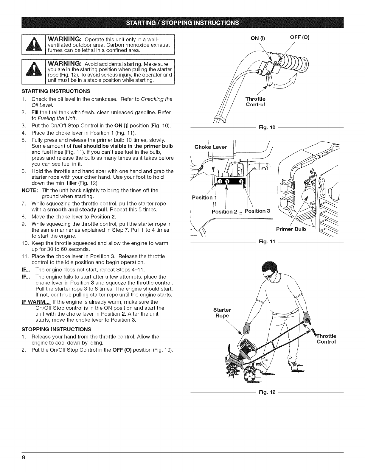
_ ARNING: Operate this unit only in a well-
_ ARNING" Avoid accidental starting. Make sure
STARTING iNSTRUCTiONS
1. Check the oil level in the crankcase. Refer to Checking the
2. Fill the fuel tank with fresh, clean unleaded gasoline. Refer
3. Put the On/Off Stop Control in the ON [I] position (Fig. 10).
4. Place the choke lever in Position 1 (Fig. 11).
5. Fully press and release the primer bulb 10 times, slowly.
6. Hold the throttle and handlebar with one hand and grab the
NOTE: Tilt the unit back slightly to bring the tines off the
7. While squeezing the throttle control, pull the starter rope
8. Move the choke lever to Position 2.
9. While squeezing the throttle control, pull the starter rope in
10. Keep the throttle squeezed and allow the engine to warm
11. Place the choke lever in Position 3. Release the throttle
IF... The engine does not start, repeat Steps 4-11.
IF... The engine fails to start after a few attempts, place the
IF WARM... If the engine is already warm, make sure the
STOPPING INSTRUCTIONS
1. Release your hand from the throttle control. Allow the
2. Put the On/Off Stop Control in the OFF (O) position (Fig. 10).
ventilated outdoor area. Carbon monoxide exhaust
fumes can be lethal in a confined area.
you are in the starting position when pulling the starter
rope (Fig. 12). To avoid serious injury, the operator and
unit must be in a stable position while starting.
Oil Level.
to Fueling the Unit.
Some amount of fuel should be visible in the primer bulb
and fuel lines (Fig. 11). If you can't see fuel in the bulb,
press and release the bulb as many times as it takes before
you can see fuel in it.
starter rope with your other hand. Use your foot to hold
down the mini tiller (Fig. 12).
ground when starting.
with a smooth and steady pull. Repeat this 5 times.
the same manner as explained in Step 7. Pull 1 to 4 times
to start the engine.
up for 30 to 60 seconds.
control to the idle position and begin operation.
choke lever in Position 3 and squeeze the throttle control.
Pull the starter rope 3 to 8 times. The engine should start.
If not, continue pulling starter rope until the engine starts.
On/Off Stop control is in the ON position and start the
unit with the choke lever in Position 2. After the unit
starts, move the choke lever to Position 3.
engine to cool down by idling.
ON (I) OFF (0)
Throttle
Control
Fig. 10
I
Choke Lever
f<
Position 1
Position 2 Position 3
Primer Bulb
Fig. 11
Starter
Rope
Control
Fig. 12
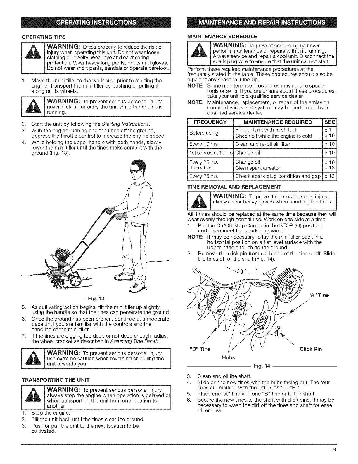
OPERATINGTiPS
MAINTENANCE SCHEDULE
injury when operating this unit. Do not wear loose
clothing or jewelry. Wear eye and ear/hearing
__J ARNING: Dress properly to reduce the risk of
1. Move the mini tiller to the work area prior to starting the
_WARN[NG: To prevent serious personal injury, j
2. Start the unit by following the Starting Instructions.
3. With the engine running and the tines off the ground,
4. While holding the upper handle with both hands, slowly
protection. Wear heavy long pants, boots and gloves.
Do not wear short pants, sandals or operate barefoot.
engine. Transport the mini tiller by pushing or pulling it
along on its wheels.
never pick-up or carry the unit while the engine is
running.
depress the throttle control to increase the engine speed.
lower the mini tiller until the tines make contact with the
ground (Fig. 13).
perform maintenance or repairs with unit running.
_ _ IWARNING: To prevent serious injury, never
Perform these required maintenance procedures at the
frequency stated in the table. These procedures should also be
a part of any seasonal tune-up.
NOTE: Some maintenance procedures may require special
NOTE: Maintenance, replacement, or repair of the emission
FREQUENCY MAINTENANCE REQUIRED SEE
Before using Check oil while the engine is cold p 10
Every 10 hrs Clean and re-oil air filter p 10
1st service at 10 hrs Change oil p 10
Every 25 hrs Change oil p 10
thereafter Clean spark arrestor p 13
Every 25 hrs Check spark plug condition and gap p 13
TINE REMOVAL AND REPLACEMENT
_ ARNING: To prevent serious personal injury, 1
All 4 tines should be replaced at the same time because they will
wear evenly through normal use. Work on one side at a time.
1. Put the On/Off Stop Control in the STOP (O) position
NOTE: it may be necessary to lay the mini tiller back in a
2. Remove the click pin from each end of the tine shaft. Slide
Always service and repair a cool unit. Disconnect the
spark plug wire to ensure that the unit cannot start.
tools or skills, if you are unsure about these procedures,
take your unit to a qualified service dealer.
control devices and system may be performed by a
qualified service dealer.
Fill fuel tank with fresh fuel p 7
always wear heavy gloves when handling the tines.
and disconnect the spark plug wire.
horizontal position on a flat level surface with the
upper handle touching the ground.
the tines off of the shaft (Fig. 14).
Fig. 13
5. As cultivating action begins, tilt the mini tiller up slightly
using the handle so that the tines can penetrate the ground.
6. Once the ground has been broken, continue at a moderate
pace until you are familiar with the controls and the
handling of the mini tiller.
7. if the tines are digging too deep or not deep enough, adjust
the wheel bracket as described in Adjusting Tine Depth.
L_ ARNING: To prevent serious personal injury, j
TRANSPORTING THE UNIT
_J ARNING: To prevent serious personal injury, rl
1. Stop the engine.
2. Tilt the unit back until the tines clear the ground.
3. Push or pull the unit to the next location to be
use extreme caution when reversing or pulling the
unit towards you.
always stop the engine when operation is delayed o
when transporting the unit from one location to
another.
cultivated.
Tine
Click Pin
Hubs
Fig. 14
3. Clean and oil the shaft.
4. Slide on the new tines with the hubs facing out. The four
tines are marked with the letters "A" or "B."
5. Place one "A" tine and one "B" tine onto the shaft.
6. Secure the new tines to the shaft with click pins. it may be
necessary to wash the dirt off the tines and shaft for ease
of removal.
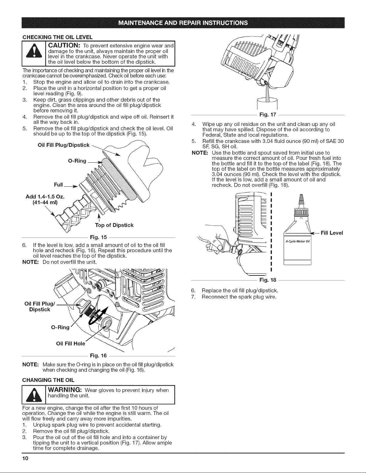
CHECKINGTHE OiL LEVEL
damage to the unit, always maintain the proper oil
_ CAUTION: To prevent extensive engine wear and I
The importance of checking and maintaining the proper oil level inthe
crankcase cannot be overemphasized. Check oil before each use:
1. Stop the engine and allow oil to drain into the crankcase.
2. Place the unit in a horizontal position to get a proper oil
3. Keep dirt, grass clippings and other debris out of the
4. Remove the oil fill plug/dipstick and wipe off oil. Reinsert it
5. Remove the oil fill plug/dipstick and check the oil level. Oil
Add 1.4=1.5 Oz.
6. If the level is low, add a small amount of oil to the oil fill
NOTE: Do not overfill the unit.
level in the crankcase. Never operate the unit with
the o eve be ow the bottom of the d pst ck. j
level reading (Fig. 9).
engine. Clean the area around the oil fill plug/dipstick
before removing it.
all the way back in.
should be up to the top of the dipstick (Fig. 15).
Oil Fill Plug/Dipstick
O-Ring __
(41-44 ml)
Top of Dipstick
Fig. 15
hole and recheck (Fig. 16). Repeat this procedure until the
oil level reaches the top of the dipstick.
Fig. 17
4.
Wipe up any oil residue on the unit and clean up any oil
that may have spilled. Dispose of the oil according to
Federal, State and local regulations.
5.
Refill the crankcase with 3.04 fluid ounce (90 ml) of SAE 30
SF, SG, SH oil.
NOTE:
Use the bottle and spout saved from initial use to
measure the correct amount of oil. Pour fresh fuel into
the bottle and fill it to the top of the label (Fig. 18). The
top of the label on the bottle measures approximately
3.04 ounces (90 ml). Check the level with the dipstick.
If the level is low, add a small amount of oil and
recheck. Do not overfill (Fig. 18).
|
|
|
|
|
|
|
|
|
|
|
4-Cycle Motor Oil 1.
|
|
|
Fill
Level
Oi_)F;IsltPcl_g
Fig. 16
NOTE: Make sure the O-ring is in place on the oil fill plug/dipstick
when checking and changing the oil (Fig. 16).
CHANGING THE OiL
I I °'°vest° he°Ih od.. 0the
For a new engine, change the oil after the first 10 hours of
operation. Change the oil while the engine is still warm. The oil
will flow freely and carry away more impurities.
1. Unplug spark plug wire to prevent accidental starting.
2. Remove the oil fill plug/dipstick.
3. Pour the oil out of the oil fill hole and into a container by
tipping the unit to a vertical position (Fig. 17). Allow ample
time for complete drainage.
10
Fig. 18
6. Replace the oil fill plug/dipstick.
7. Reconnect the spark plug wire.
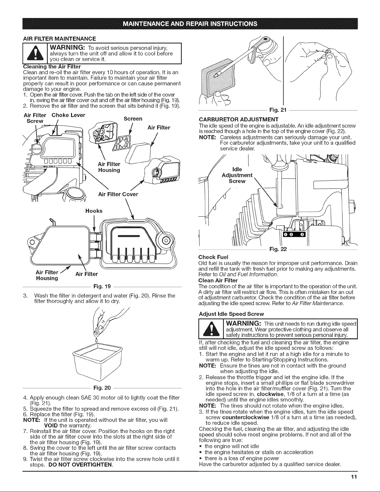
AiRFILTERMAINTENANCE
always turn the unit off and allow it to cool before
you clean or service it.
Cleaning the Air Filter
Clean and re-oil the air filter every 10 hours of operation. It is an
important item to maintain. Failure to maintain your air filter
properly can result in poor performance or can cause permanent
damage to your engine.
1. Open the air filtercover. Push the tab on the leftside of the cover
in,swing the airfilter cover out and off the air filter housing (Fig.19).
2. Remove the air filter and the screen that sits behind it (Fig. 19).
Air Filter Choke Lever
Screw Screen
Air Filter
\
Air Filter Cover
Hooks
Fig. 21
CARBURETOR ADJUSTMENT
The idle speed of the engine isadjustable. An idleadjustment screw
is reached though a hole in the top of the engine cover (Fig. 22).
NOTE: Careless adjustments can seriously damage your unit.
For carburetor adjustments, take your unit to a qualified
service dealer.
Screw
Air Filter Air Filter
Housing
Fig. 19
3.
Wash the filter in detergent and water (Fig. 20). Rinse the
filter thoroughly and allow it to dry.
U
Fig. 20
4. Apply enough clean SAE 30 motor oil to lightly coat the filter
(Fig. 21).
5. Squeeze the filter to spread and remove excess oil (Fig. 21).
6. Replace the filter (Fig. 19).
NOTE: If the unit is operated without the air filter, you will
7. Reinstall the air filter cover. Position the hooks on the right
8. Swing the cover to the left until the air filter screw contacts
9. Twist the air filter screw clockwise into the screw hole until it
VOiD the warranty.
side of the air filter cover into the slots at the right side of
the air filter housing (Fig. 19).
the air filter housing (Fig. 19).
stops. DO NOT OVERTIGHTEN.
Fig. 22
Check Fuel
Old fuel is usually the reason for improper unit performance. Drain
and refill the tank with fresh fuel prior to making any adjustments.
Refer to Oil and Fuel Information.
Clean Air Filter
The condition of the air filter is important to the operation of the unit.
A dirty air filter will restrict air flow. This isoften mistaken for an out
of adjustment carburetor. Check the condition of the air filter before
adjusting the idle speed screw. Refer to Air Filter Maintenance.
Adjust Idle Speed Screw
I _ IWARNING: Thisunitneedstorunduringidlespeedl
If,aftercheckingthefueland cleaningtheairfilter,theengine
stillwillnotidle,adjusttheidlespeed screw as follows:
I.Starttheengine and letitrunata high idlefora minuteto
warm up. Referto Starting/StoppingInstructions.
NOTE: Ensurethetinesarenot incontactwiththeground
2.Release thethrottletriggerand lettheengine idle.Ifthe
enginestops,inserta smallphillipsor flatbladescrewdriver
intothe holeintheairfilter/mufflercover(Fig.21).Turnthe
idlespeed screw in,clockwise,I/8ofa turnata time(as
needed)untilthe engineidlessmoothly.
NOTE: The tinesshouldnotrotatewhen the engineidles.
3.Ifthetinesrotatewhen the engineidles,turnthe idlespeed
screw counterclockwise 1/8 of a turn at a time (as needed),
to reduce idle speed.
Checking the fuel, cleaning the air filter, and adjusting the idle
speed should solve most engine problems. If not and all of the
following are true:
* the engine will not idle
* the engine hesitates or stalls on acceleration
* there is a loss of engine power
Have the carburetor adjusted by a qualified service dealer.
adjustment.Wear protectiveclothingand observeall I
safetyinstructionstopreventseriouspersonalinjury. I
when adjustingtheidle.
11
 Loading...