

Craftsman 316292621 Owner’s Manual
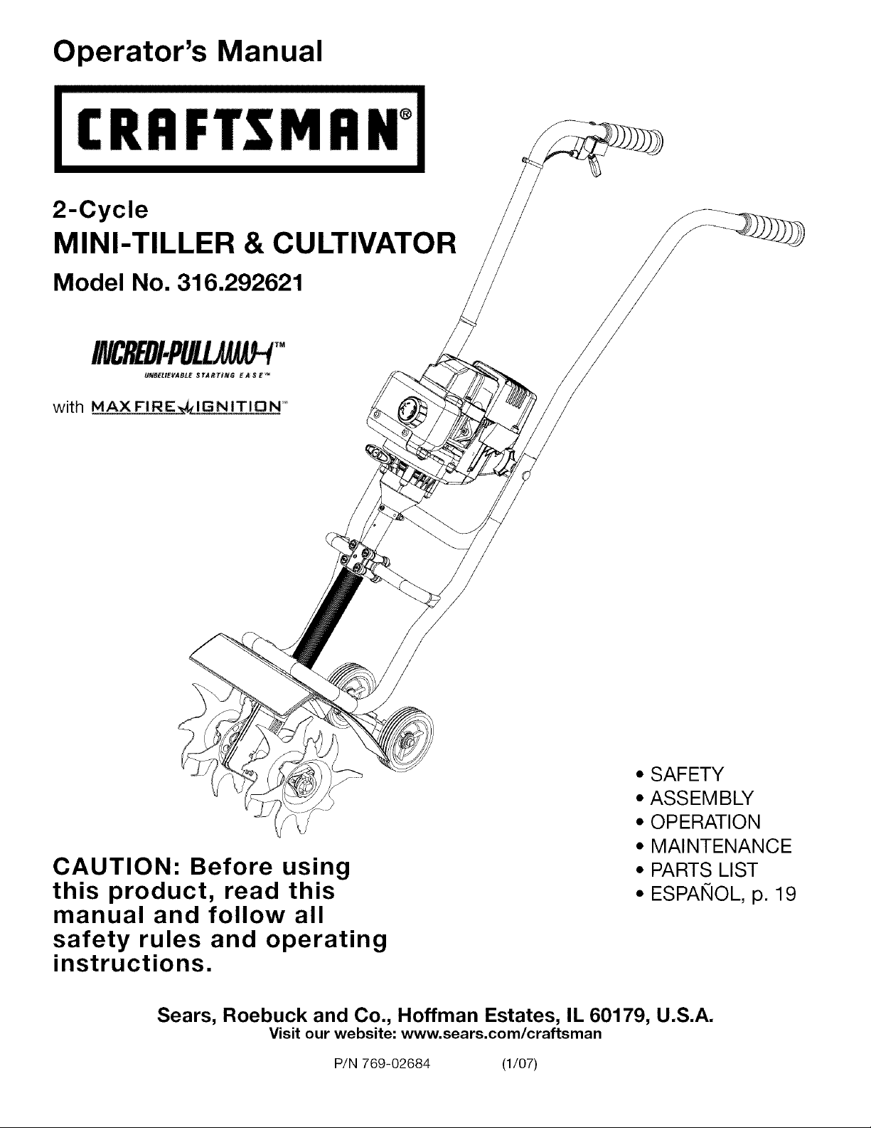
Operator's Manual
CRRFr ;MRN°
2-Cycle
MINI-TILLER & CULTIVATOR
Model No. 316.292621
CAUTION: Before using
this product, read this
manual and follow all
safety rules and operating
instructions.
Sears, Roebuck and Co., Hoffman Estates, IL 60179, U.S.A.
Visit our website" www.sears.com/craftsman
P/N 769-02684 (1/07)
• SAFETY
• ASSEMBLY
• OPERATION
• MAINTENANCE
• PARTS LIST
• ESPANOL, p. 19
TABLE OF CONTENTS
Warranty ................................. 2
Service Information ......................... 2
Rules for Safe Operation ..................... 3
Know Your Unit ............................ 6
Assembly Instructions ....................... 7
Oil and Fuel Information ...................... 9
Starting/Stopping Instructions ................ 10
Operating Instructions ...................... 11
Maintenance and Repair Instructions ........... 12
Cleaning and Storage ....................... 15
Troubleshooting Chart ...................... 16
Specifications ............................. 17
Parts List ............................. 36-37
Repair Protection Agreement .... Inside Back Cover
Service Numbers ................... Back Cover
Full Two-Year Warranty on Craftsman Mini-Tiller and Cultivator
For two (2) years from the date of purchase, if this Craftsman Equipment is maintained, lubricated, and tuned up
according to the instructions to the operator's manual, Sears will repair or replace free of charge any parts found to be
defective in material or workmanship. Warranty service is available free of charge by returning Craftsman equipment to
your nearest Sears Service Center. In-home warranty service is available but a trip charge will apply. This Warranty
applies only while this product is in the United States.
This Warranty does not cover:
• Expendable items which become worn during normal use, such as spark plugs, air cleaners, belts, and oil filters.
• Tire replacement or repair caused by punctures from outside objects, such as nails, thorns, stumps, or glass.
• Repairs necessary because of operator abuse, including but not limited to, damage caused by objects, such as stones
or metal debris, oversized stock, impacting objects that bend the frame or crankshaft, or over-speeding the engine.
• Repairs necessary because of operator negligence, including but not limited to, electrical and mechanical damage
caused by improper storage, failure to use the proper grade and amount of engine oil, or failure to maintain the
equipment according to the instructions contained in the operator's manual.
• Engine (fuel system) cleaning or repairs caused by fuel determine to be contaminated or oxidized (stale). In general,
fuel should be used within 30 days of its purchase date.
• Equipment used for commercial or rental purposes.
TO LOCATE THE NEAREST SEARS SERVICE CENTER OR TO SCHEDULE SERVICE, SIMPLY CONTACT SEARS AT
1-800-4-MY-HOME®.
This warranty gives you specific legal rights and you may also have other rights, which vary from state to state.
CALIFORNIA PROPOSITION 65 WARNING
THE ENGINE EXHAUST FROM THIS
PRODUCT CONTAINS CHEMICALS
KNOWN TO THE STATE OF CALIFORNIA
TO CAUSE CANCER, BIRTH DEFECTS
OR OTHER REPRODUCTIVE HARM.
SPARK ARRESTOR NOTE
NOTE: For users on U.S. Forest Land and in the
states of California, Maine, Oregon and Washington.
All U.S. Forest Land and the state of California (Public
Resources Codes 4442 and 4443), Oregon and
Washington require, by law that certain internal
combustion engines operated on forest brush and/or
grass-covered areas be equipped with a spark arrestor,
maintained in effective working order, or the engine be
constructed, equipped and maintained for the prevention
of fire. Check with your state or local authorities for
regulations pertaining to these requirements. Failure to
follow these requirements could subject you to liability or
a fine. This unit is factory equipped with a spark
arrestor. If it requires replacement, ask your LOCAL
SERVICE DEALER to install the Accessory Part
#753-04925 Spark Arrestor Kit.
The purpose of safety symbols is to attract your
attention to possible dangers. The safety symbols,
and their explanations, deserve your careful attention
and understanding. The safety warnings do not by
themselves eliminate any danger. The instructions or
warnings they give are not substitutes for proper
accident prevention measures.
SYMBOL MEANING
I SYMBOL MEANING I
DANGER: Failure to obey a
result in serious injury to yourself or to
others. Always follow the safety precautions
to reduce the risk of fire, electric shock and
personal injury.
safety warning will
SAFETY ALERT: Indicates
warning or caution. Attention is required in
order to avoid serious personal injury. May
be used in conjunction with other symbols
or pictographs.
NOTE: Advises you of information or instructions vital to
the operation or maintenance of the equipment.
Read the Operator's Manual(s) and follow all
warnings and safety instructions.
Failure to do so can result in serious injury to the
operator and/or bystanders.
danger,
• IMPORTANT SAFETY INSTRUCTIONS •
READ ALL INSTRUCTIONS BEFORE
OPERATING
• Read the instructions carefully. Be familiar with the
controls and proper use of the unit.
• Do not operate this unit when tired, ill, or under the
influence of alcohol, drugs, or medication.
• Children and teens under the age of 15 must not use
the unit, except for teens guided by an adult.
• All guards and safety attachments must be installed
properly before operating the unit.
• Inspect the unit before use. Replace damaged parts.
Check for fuel leaks. Make sure all fasteners are in
place and secure. Replace parts that are cracked,
chipped, or damaged in any way. Do not operate the
unit with loose or damaged parts.
• Carefully inspect the area before starting the unit.
Remove all debris and hard or sharp objects such as
glass, wire, etc.
• Be aware of the risk of injury to the head, hands and
feet.
• Clear the area of children, bystanders, and pets. At a
minimum, keep all children, bystanders, and pets
outside a 50 feet (15 m) radius; there still may be a risk to
bystanders from thrown objects. Bystanders should be
encouraged to wear eye protection. If you are
approached, stop the unit immediately.
• Squeeze the throttle control and check that it returns
auto-matically to the idle position. Make all
adjustments or repairs before using unit.
WARNING: Failure to obey a
result in injury to yourself and others.
Always follow the safety precautions to
reduce the risk of fire, electric shock and
personal injury.
CAUTION: safety warning may
result in property damage or personal injury
to yourself or to others. Always follow the
safety precautions to reduce the risk of fire,
electric shock and personal injury.
safety warning can
Failure to obey a
SAFETY WARNINGS FOR GAS UNITS
• Store fuel only in containers specifically designed and
approved for the storage of such materials.
A IIAIAl:::l I%11I 11 .. Gasolineishighly
I wwrt= ==IB=I,_,A. flammable, and its
vapors can explode if ignited. Take the
fo ow ng precaut ons:
• Avoid creating a source of ignition for spilled fuel. Do
not start the engine until fuel vapors dissipate.
• Always stop the engine and allow it to cool before
filling the fuel tank. Never remove the cap of the fuel
tank, or add fuel, when the engine is hot. Never
operate the unit without the fuel cap securely in place.
Loosen the fuel tank cap slowly to relieve any pressure
in the tank.
• Add fuel in a clean, well-ventilated outdoor area where
there are no sparks or flames. Slowly remove the fuel
cap only after stopping engine. Do not smoke while
fueling or mixing fuel. Wipe up any spilled fuel from the
unit immediately. Always wipe unit dry before using.
• Move the unit at least 30 feet (9.1 m) from the fueling
source and site before starting the engine. Do not
smoke or allow sparks and open flames near the area
while adding fuel or operating the unit.
WHILE OPERATING
• Never start or run the unit inside a closed room or
building. Breathing exhaust fumes can kill. Operate
this unit only in a well ventilated outdoor area.
• Wear safety glasses or goggles that meet ANSI Z87.1
standards and are marked as such. Wear ear/hearing
protection when operating this unit. Wear a face or dust
mask if the operation is dusty.
• Wear heavy, long pants, boots, gloves and a long-
sleeved shirt. Do not wear loose clothing, jewelry, short
pants, sandals or go barefoot. Secure hair above
shoulder level.
• This unit has a clutch. The tines remain stationary
when the engine is idling. If they do not, have the unit
adjusted by an authorized service technician.
• Be sure the tines are not in contact with anything
before starting the unit.
• Use the unit only in daylight or good artificial light.
• Avoid accidental starting. Be in the starting position
whenever pulling the starter rope. The operator and unit
must be in a stable position while starting. See
Starting/Stopping Instructions.
• Use the right tool. Only use this tool for the purpose
intended.
• Use extreme caution when reversing or pulling the unit
towards you.
• Do not overreach. Always keep proper footing and
balance. Take extra care when working on steep
slopes or inclines.
• Always hold the unit with both hands when operating.
Keep a firm grip on the grips.
• Keep hands, face, and feet at a distance from all moving
parts. Do not touch or try to stop the tines when they are
rotating.
• Do not touch the engine or muffler. These parts get
extremely hot from operation, even after the unit isturned
off.
• Do not operate the engine faster than the speed
needed to cultivate. Do not run the engine at high
speed when you are not cultivating.
• Always stop the engine when cultivating is delayed or
when walking from one cultivating location to another.
• If you strike or become entangled with a foreign object,
stop the engine immediately and check for damage. Do
not operate before repairing damage. Do not operate the
unit with loose or damaged parts.
• Stop the unit, switch the engine to off, and disconnect
the spark plug for maintenance or repair.
• Use only original equipment manufacturer
replacement parts and accessories for this unit. These
are available from your authorized service dealer. Use
of any unauthorized parts or accessories could lead to
serious injury to the user, or damage to the unit, and
void your warranty.
• Keep unit clean of vegetation and other materials.
They may become lodged between the tines and
guard.
• To reduce fire hazard, replace faulty muffler and spark
arrestor, keep the engine and muffler free from grass,
leaves, excessive grease or carbon build up.
AFTER USE
• Clean tines with a household cleaner to remove any
gum buildup. Oil the tines with machine oil to prevent
rust.
OTHER SAFETY WARNINGS
• Never store a fueled unit inside a building where fumes
may reach an open flame or spark.
• Allow the engine to cool before storing or transporting.
Be sure to secure the unit while transporting.
• Store the unit in a dry area, locked up or up high to
prevent unauthorized use or damage, out of the reach
of children.
• Never douse or squirt the unit with water or any other
liquid. Keep handles dry, clean and free from debris.
Clean after each use, see Cleaning and Storage
instructions.
• Keep these instructions. Refer to them often and use
them to instruct other users. If you loan someone this
unit, also loan them these instructions.
SAVE THESE INSTRUCTIONS

SAFETY AND INTERNATIONAL SYMBOLS
This operator's manual describes safety and international symbols and pictographs that may appear on this product.
Read the operator's manual for complete safety, assembly, operating and maintenance and repair information.
SYMBOL MEANING SYMBOL
Indicates danger, warning, or / "_'._-Ib"
• SAFETY ALERT SYMBOL _e_l_
caution. May be used in conjunction
with other symbols or pictographs. -/_/_
• WARNING - READ OPERATOR'S
MANUAL
Read the Operator's Manual(s) and
follow all warnings and safety
instructions. Failure to do so can
result in serious injury to the
operator and/or bystanders.
WEAR EYE AND HEARING
PROTECTION
/_jl '
I
O
WARNING: Thrown
objects and loud noise can cause
severe eye injury and hearing loss.
Wear eye protection meeting ANSI
Z87.1-1989 standards and ear
protection when operating this unit.
Use a full face shield when needed.
• KEEP BYSTANDERS AWAY
WARNING: Keep all
bystanders, especially children and
pets, at least 50 feet (15 m.) from the
operating area.
|
MEANING
• THROWN OBJECTS AND
ROTATING CUTTER CAN CAUSE
SEVERE INJURY
WARNING: Do not
operate without the proper guards in
place. Keep away from the rotating
tines.
• ON/OFF STOP CONTROL
ON / START / RUN
• ON/OFF STOP CONTROL
OFF or STOP
• HOT SURFACE WARNING
Do not touch a hot muffler or
cylinder. You may get burned. These
parts get extremely hot from
operation. When turned off they
remain hot for a short time.
GARDEN CULTIVATORS-
ROTATING TINES CAN CAUSE
SEVERE INJURY
• UNLEADED FUEL
Always use clean, fresh unleaded fuel.
• OIL
Refer to operator's manual for the
proper type of oil.
WARNING: Stop the
engine and allow the tines to stop
before installing or removing tines,
or before cleaning or performing any
maintenance. Keep hands and feet
away from rotating tines.
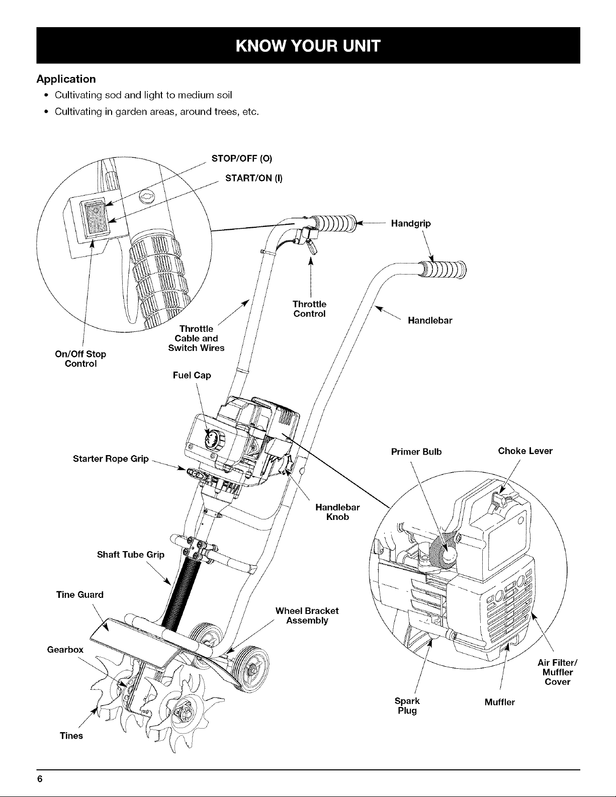
Application
• Cultivating sod and light to medium soil
• Cultivating in garden areas, around trees, etc.
STOP/OFF (O)
START/ON (I)
Throttle
Cable and
On/Off Stop
Control
Switch Wires
Fuel Cap
T
Throttle
Control
Handgrip
Handlebar
Starter Rope Grip -._
Shaft Tube Grip
Tine Guard
Gearbox
Tines
Handlebar
Knob
Wheel Bracket
Assembly
Primer Bulb
Spark
Plug
Choke Lever
Air Filter/
Muffler
Cover
Muffler
ASSEMBLING THE UNIT
Before operating, position the unit's handlebars.
NOTE: You may also need to reposition the wheel height
before using the cultivator. Refer to the Adjusting
Tine Depth section.
Begin by carefully unpacking the contents and making
sure that nothing is damaged.
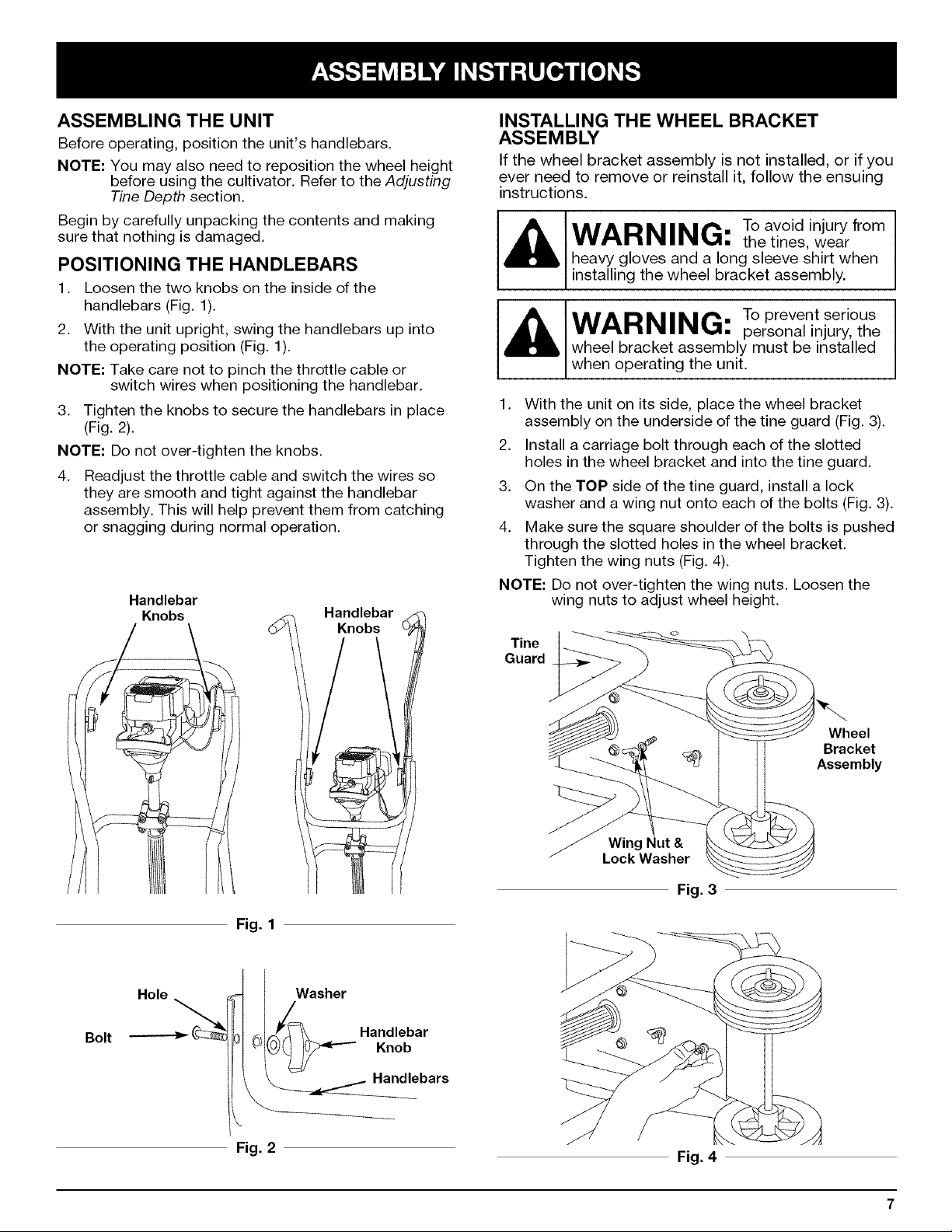
POSITIONING THE HANDLEBARS
1. Loosen the two knobs on the inside of the
handlebars (Fig. 1).
2. With the unit upright, swing the handlebars up into
the operating position (Fig. 1).
NOTE: Take care not to pinch the throttle cable or
switch wires when positioning the handlebar.
3. Tighten the knobs to secure the handlebars in place
(Fig. 2).
NOTE: Do not over-tighten the knobs.
,
Readjust the throttle cable and switch the wires so
they are smooth and tight against the handlebar
assembly. This will help prevent them from catching
or snagging during normal operation.
Handlebar
Knobs
Handlebar
Knobs
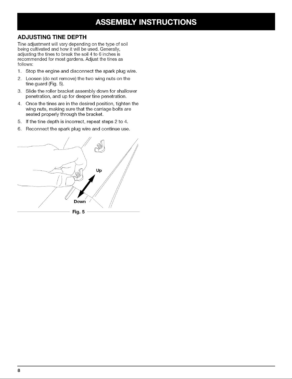
INSTALLING THE WHEEL BRACKET
ASSEMBLY
If the wheel bracket assembly is not installed, or if you
ever need to remove or reinstall it, follow the ensuing
instructions.
WARNING: Toavoidinjury from
heavy gloves and a long sleeve shirt when
installing the wheel bracket assembly.
WARNING: Toprevent serious
wheel bracket assembly must be installed
when operating the unit.
1. With the unit on its side, place the wheel bracket
assembly on the underside of the tine guard (Fig. 3).
2. Install a carriage bolt through each of the slotted
holes in the wheel bracket and into the tine guard.
3. On the TOP side of the tine guard, install a lock
washer and a wing nut onto each of the bolts (Fig. 3).
4. Make sure the square shoulder of the bolts is pushed
through the slotted holes in the wheel bracket.
Tighten the wing nuts (Fig. 4).
NOTE: Do not over-tighten the wing nuts. Loosen the
wing nuts to adjust wheel height.
Tine
Guard
the tines, wear
personal injury, the
Fig. 1
Hole Washer
Bolt _ I 0; Handlebar
Fig. 2
Knob
Handlebars
Wheel
Bracket
Assembly
Wing
Lock Washer
Fig. 3
Fig. 4
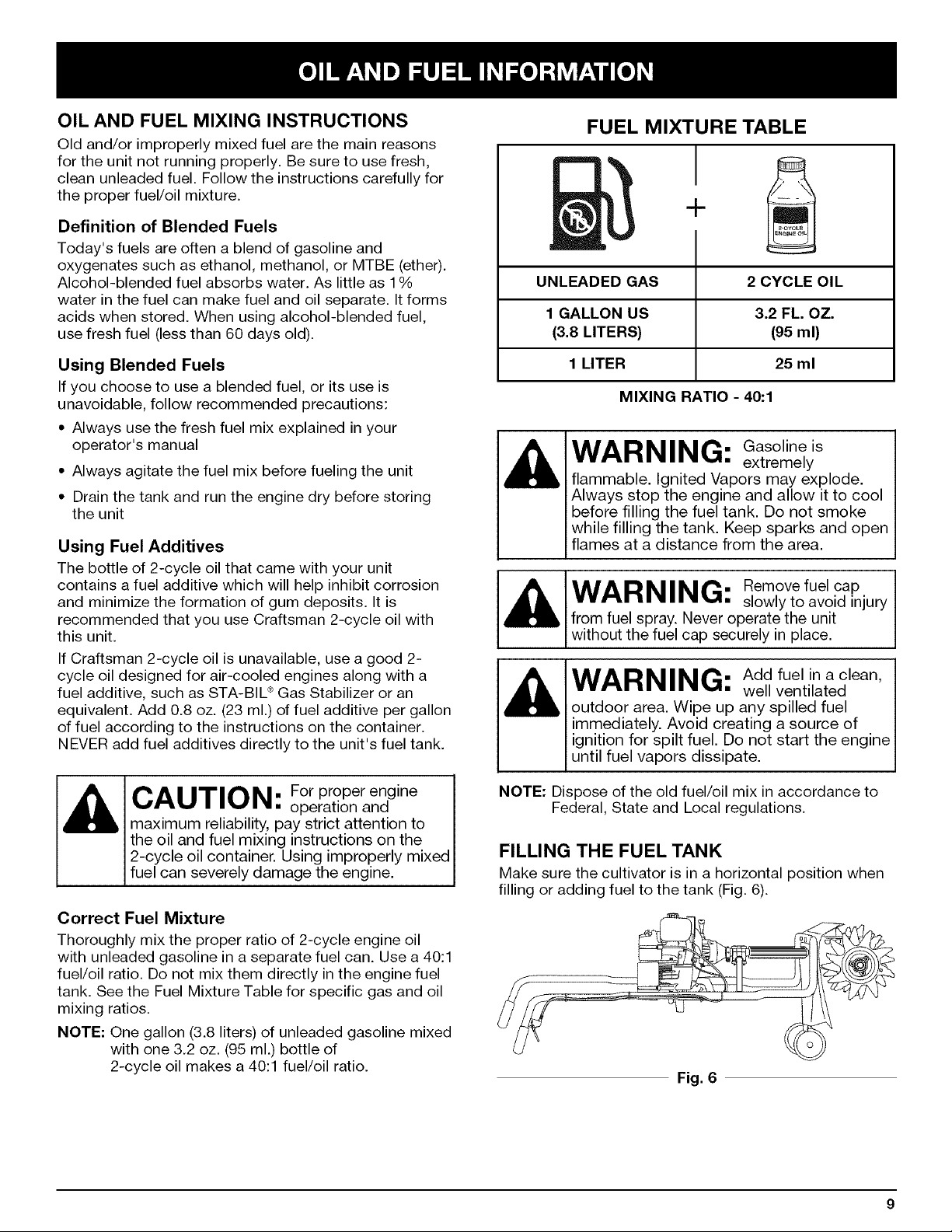
ADJUSTING TINE DEPTH
Tine adjustment will vary depending on the type of soil
being cultivated and how it will be used. Generally,
adjusting the tines to break the soil 4to 6 inches is
recommended for most gardens. Adjust the tines as
follows:
1. Stop the engine and disconnect the spark plug wire.
2. Loosen (do not remove) the two wing nuts on the
tine guard (Fig. 5).
3. Slide the roller bracket assembly down for shallower
penetration, and up for deeper tine penetration.
4. Once the tines are in the desired position, tighten the
wing nuts, making sure that the carriage bolts are
seated properly through the bracket.
5. If the tine depth is incorrect, repeat steps 2 to 4.
6. Reconnect the spark plug wire and continue use.
Up
Down \,
Fig. 5
\\
OIL AND FUEL MIXING INSTRUCTIONS
Old and/or improperly mixed fuel are the main reasons
for the unit not running properly. Be sure to use fresh,
clean unleaded fuel. Follow the instructions carefully for
the proper fuel/oil mixture.
Definition of Blended Fuels
Today's fuels are often a blend of gasoline and
oxygenates such as ethanol, methanol, or MTBE (ether).
Alcohol-blended fuel absorbs water. As little as 1%
water in the fuel can make fuel and oil separate. It forms
acids when stored. When using alcohol-blended fuel,
use fresh fuel (less than 60 days old).
FUEL MIXTURE TABLE
UNLEADED GAS 2 CYCLE OIL
1 GALLON US 3.2 FL. OZ.
(3.8 LITERS) (95 ml)
Using Blended Fuels
If you choose to use a blended fuel, or its use is
unavoidable, follow recommended precautions:
• Always use the fresh fuel mix explained in your
operator's manual
• Always agitate the fuel mix before fueling the unit
• Drain the tank and run the engine dry before storing
the unit
Using Fuel Additives
The bottle of 2-cycle oil that came with your unit
contains a fuel additive which will help inhibit corrosion
and minimize the formation of gum deposits. It is
recommended that you use Craftsman 2-cycle oil with
this unit.
If Craftsman 2-cycle oil is unavailable, use a good 2-
cycle oil designed for air-cooled engines along with a
fuel additive, such as STA-BIL ®Gas Stabilizer or an
equivalent. Add 0.8 oz. (23 ml.) of fuel additive per gallon
of fuel according to the instructions on the container.
NEVER add fuel additives directly to the unit's fuel tank.
CAUTION: For proper engine
maximum reliability, pay strict attention to
the oil and fuel mixing instructions on the
2-cycle oil container. Using improperly mixed
fuel can severely damage the engine.
Correct Fuel Mixture
Thoroughly mix the proper ratio of 2-cycle engine oil
with unleaded gasoline in a separate fuel can. Use a 40:1
fuel/oil ratio. Do not mix them directly in the engine fuel
tank. See the Fuel Mixture Table for specific gas and oil
mixing ratios.
NOTE: One gallon (3.8 liters) of unleaded gasoline mixed
with one 3.2 oz. (95 ml.) bottle of
2-cycle oil makes a 40:1 fuel/oil ratio.
operation and
1 LITER 25 ml
MIXING RATIO - 40:1
WARNING: Gasolineis
flammable. Ignited Vapors may explode.
Always stop the engine and allow it to cool
before filling the fuel tank. Do not smoke
while filling the tank. Keep sparks and open
flames at a distance from the area.
WARNING: Remove fuel cap
from fuel spray. Never operate the unit
without the fuel cap securely in place.
WARNING: Add fuel in a clean,
outdoor area. Wipe up any spilled fuel
immediately. Avoid creating a source of
ignition for spilt fuel. Do not start the engine
until fuel vapors dissipate.
NOTE: Dispose of the old fuel/oil mix in accordance to
Federal, State and Local regulations.
extremely
slowly to avoid injury
well ventilated
FILLING THE FUEL TANK
Make sure the cultivator is in a horizontal position when
filling or adding fuel to the tank (Fig. 6).
Fig. 6
WARNING: Operatethis unit only in a
area. Carbon monoxide exhaust fumes can be lethal in
a confined area.
well- ventiJated outdoor
OFF (O) (_
WARNING: Avoid accidental starting.
starting position when pulling the starter rope
(Fig. 10). To avoid serious injury, the operator and unit
must be in a stable position while starting.
Make sure you are in the
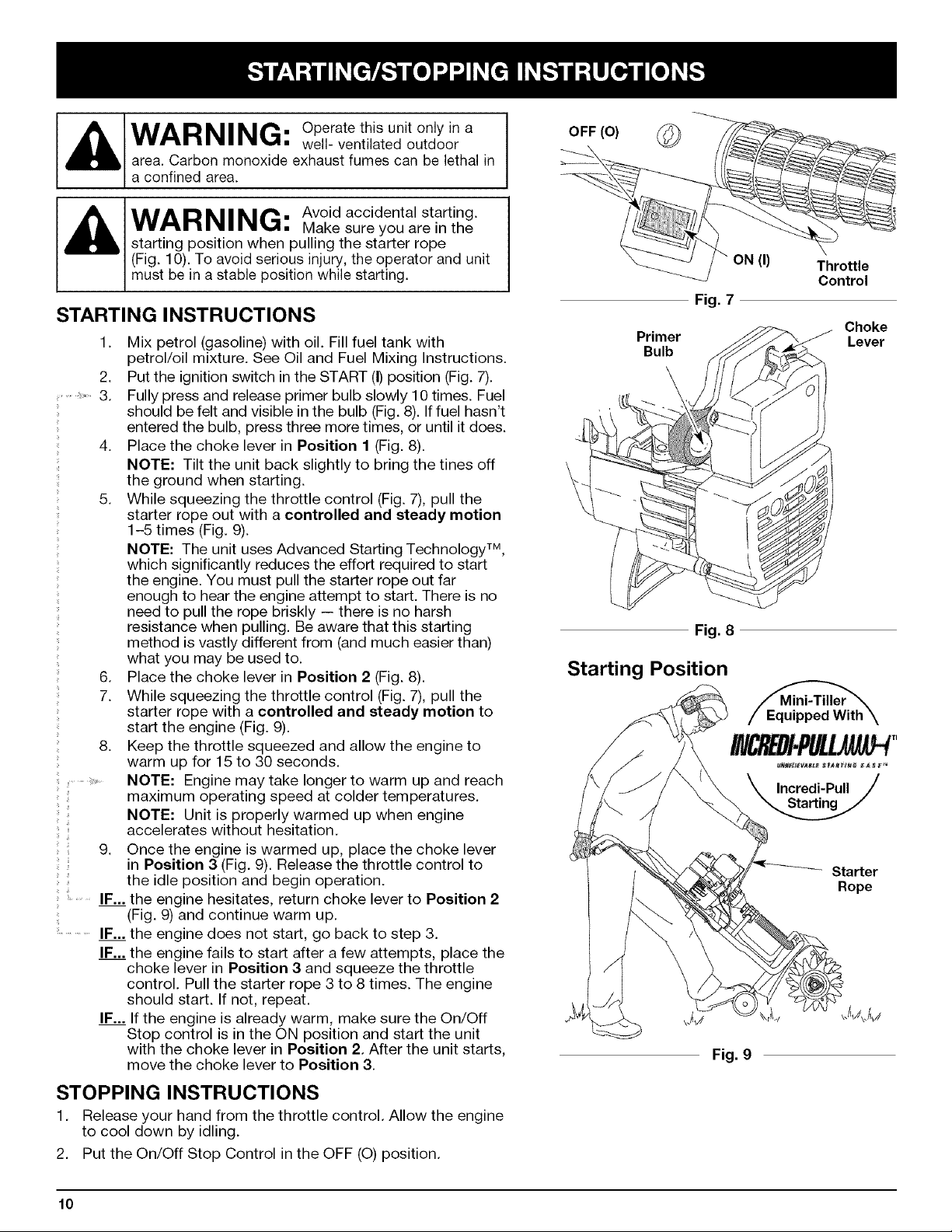
STARTING INSTRUCTIONS
1. Mix petrol (gasoline) with oil. Fill fuel tank with
petrol/oil mixture. See Oil and Fuel Mixing Instructions.
2. Put the ignition switch in the START (I)position (Fig. 7).
........ 3. Fully press and release primer bulb slowly 10 times. Fuel
should be felt and visible in the bulb (Fig.8). If fuel hasn't
entered the bulb, press three more times, or until it does.
4. Place the choke lever in Position 1 (Fig. 8).
NOTE: Tilt the unit back slightly to bring the tines off
the ground when starting.
5. While squeezing the throttle control (Fig. 7), pull the
starter rope out with a controlled and steady motion
1-5 times (Fig. 9).
NOTE: The unit uses Advanced Starting Technology TM,
which significantly reduces the effort required to start
the engine. You must pull the starter rope out far
enough to hear the engine attempt to start. There is no
need to pull the rope briskly -- there is no harsh
resistance when pulling. Be aware that this starting
method is vastly different from (and much easier than)
what you may be used to.
6. Place the choke lever in Position 2 (Fig. 8).
7. While squeezing the throttle control (Fig. 7), pull the
starter rope with a controlled and steady motion to
start the engine (Fig. 9).
8. Keep the throttle squeezed and allow the engine to
warm up for 15 to 30 seconds.
NOTE: Engine may take longer to warm up and reach
maximum operating speed at colder temperatures.
.... accelerates without hesitation.
ii
.........IF... the engine hesitates, return choke lever to Position 2
NOTE: Unit is properly warmed up when engine
9. Once the engine is warmed up, place the choke lever
in Position 3 (Fig. 9). Release the throttle control to
the idle position and begin operation.
(Fig. 9) and continue warm up.
IF... the engine does not start, go back to step 3.
IF... the engine fails to start after a few attempts, place the
choke lever in Position 3 and squeeze the throttle
control. Pull the starter rope 3 to 8 times. The engine
should start. If not, repeat.
IF... If the engine is already warm, make sure the On/Off
Stop control is in the ON position and start the unit
with the choke lever in Position 2. After the unit starts,
move the choke lever to Position 3.
Fig. 7
Primer
Bulb
Fig. 8
Starting Position
ON (I)
Fig. 9
Throttle
Control
Choke
Lever
Incredi-Pull
Starter
Rope
STOPPING INSTRUCTIONS
1. Release your hand from the throttle control. Allow the engine
to cool down by idling.
2. Put the On/Off Stop Control in the OFF (O)position.
10
OPERATING TIPS
WARNING: Dress properly to
injury when operating this unit. Do not
wear loose clothing or jewelry. Wear eye
and ear/hearing protection. Wear heavy
long pants, boots and gloves. Do not wear
short pants, sandals or operate barefoot.
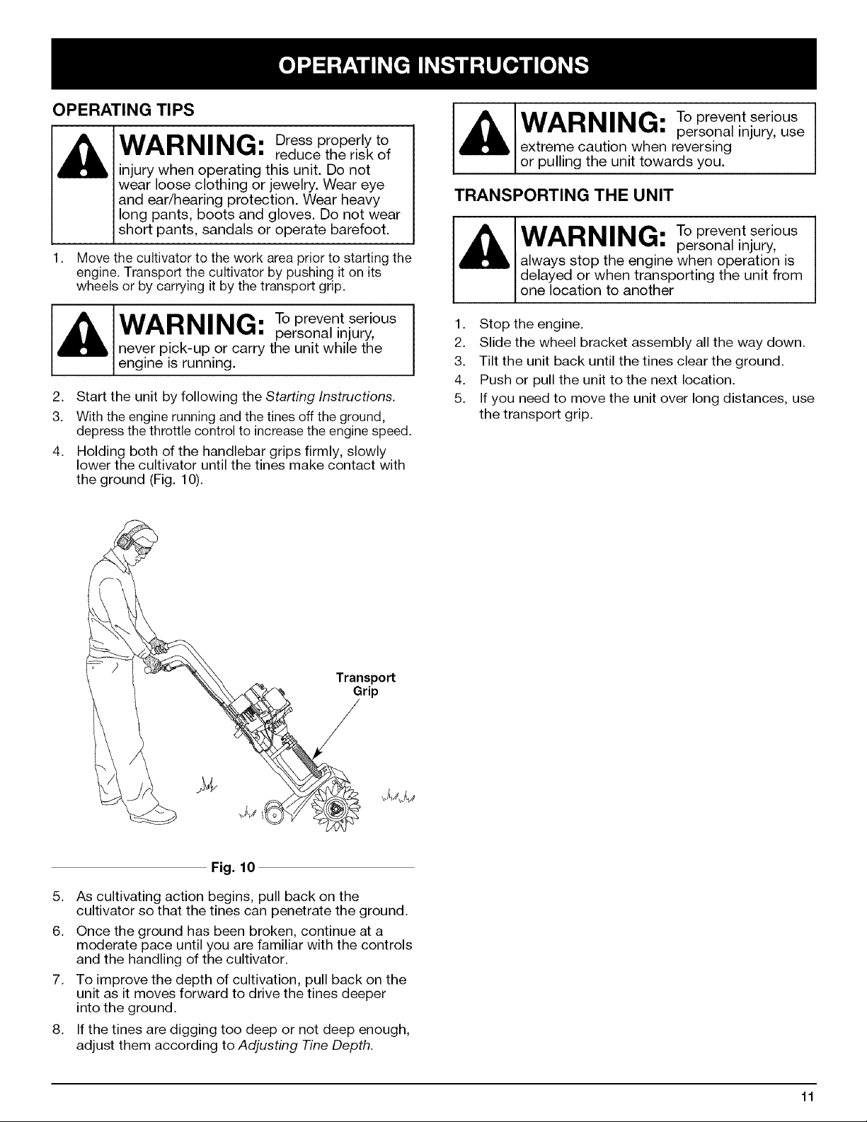
1.
Move the cultivator to the work area prior to starting the
engine. Transport the cultivator by pushing it on its
wheels or by carrying it by the transport grip.
reduce the risk of
WARNING: Toprevent serious
extreme caution when reversing
or pulling the unit towards you.
TRANSPORTING THE UNIT
WARNING: Toprevent serious
always stop the engine when operation is
delayed or when transporting the unit from
one location to another
personal injury, use
personal injury,
WARNING: Toprevent serious
never pick-up or carry the unit while the
engine is running.
2. Start the unit by following the Starting Instructions.
3. With the engine running and the tines off the ground,
depress the throttle control to increase the engine speed.
4. Holding both of the handlebar grips firmly, slowly
lower the cultivator until the tines make contact with
the ground (Fig. 10).
personal injury,
Transport
Grip
1. Stop the engine.
2. Slide the wheel bracket assembly all the way down.
3. Tilt the unit back until the tines clear the ground.
4. Push or pull the unit to the next location.
5. If you need to move the unit over long distances, use
the transport grip.
Fig. 10
5. As cultivating action begins, pull back on the
cultivator so that the tines can penetrate the ground.
6. Once the ground has been broken, continue at a
moderate pace until you are familiar with the controls
and the handling of the cultivator.
7. To improve the depth of cultivation, pull back on the
unit as it moves forward to drive the tines deeper
into the ground.
8. If the tines are digging too deep or not deep enough,
adjust them according to Adjusting Tine Depth.
11
MAINTENANCE SCHEDULE
Perform these required maintenance procedures at the
frequency stated in the table. These procedures should
also be a part of any seasonal tune-up.
NOTE: Maintenance, replacement, or repair of the
emission control devices and system may be
performed by a Sears or other qualified service
dealer. Call 1-800-4-MY-HOME® for more
information.
NOTE: Some maintenance procedures may require
special tools or skills. If you are unsure about
these procedures, take your unit to a Sears or
other qualified service dealer. Call 1-800-4-MY-
HOME® for more information.
In order to assure peak performance of your engine,
inspection of the engine exhaust port may be necessary
after 50 hours of operation. If you notice lost RPM, poor
performance or general lack of acceleration, this service
may be required. If you feel your engine is in need of this
WARNING: TOprevent serious
injury, never perform
maintenance or repairs with unit running.
Always service and repair a cool unit.
Disconnect the spark plug wire to ensure that
inspection, refer service to a Sears or other qualified
service dealer. Call 1-800-4-MY-HOME® for more
information. DO NOT attempt to perform this process
yourself as engine damage may result from contaminants
involved in the cleaning process for the port.
the unit cannot start.
FREQUENCY MAINTENANCE REQUIRED REFER TO
Before starting engine Fill fuel tank with fresh fuel mix Page 9
Every 10 hours Clean and re-oil air filter Page 13
Every 25 hours
Every 50 hours Inspect exhaust port and spark arrestor screen for clogging or
Check and clean spark arrestor Page 13
Check spark plug condition and gap Page 14
obstruction to assure maximum performance levels Pages 13 & 14
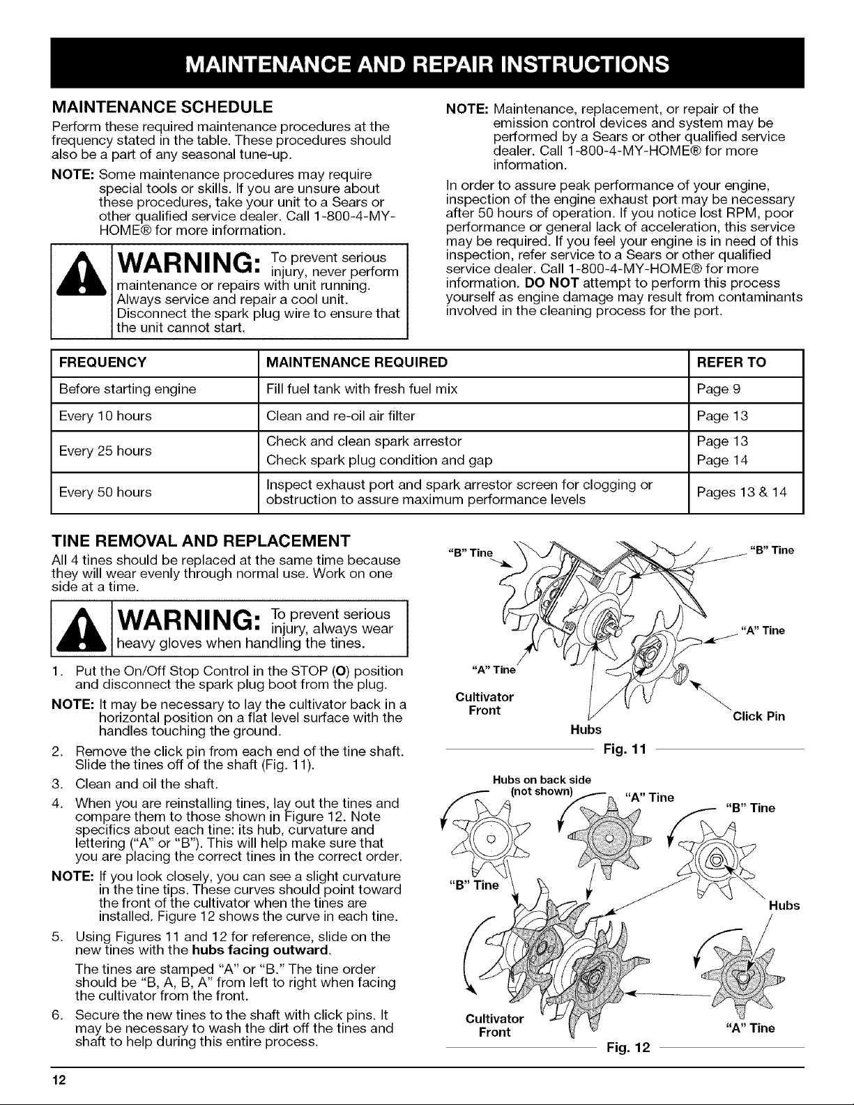
TINE REMOVAL AND REPLACEMENT
All 4 tines should be replaced at the same time because
they will wear evenly through normal use. Work on one
side at a time.
WARNING: Toprevent serious
injury, always wear
heavy gloves when handling the tines.
1. Put the On/Off Stop Control in the STOP (0) position
and disconnect the spark plug boot from the plug.
NOTE: It may be necessary to lay the cultivator back in a
horizontal position on a flat level surface with the
handles touching the ground.
2. Remove the click pin from each end of the tine shaft.
Slide the tines off of the shaft (Fig. 11).
3. Clean and oil the shaft.
4. When you are reinstalling tines, lay out the tines and
compare them to those shown in Figure 12. Note
specifics about each tine: its hub, curvature and
lettering ("A" or "B'). This will help make sure that
you are placing the correct tines in the correct order.
NOTE: If you look closely, you can see a slight curvature
in the tine tips. These curves should point toward
the front of the cultivator when the tines are
installed. Figure 12shows the curve in each tine.
5. Using Figures 11 and 12 for reference, slide on the
new tines with the hubs facing outward.
The tines are stamped "A" or "B." The tine order
should be "B, A, B, A" from left to right when facing
the cultivator from the front.
6. Secure the new tines to the shaft with click pins. It
may be necessary to wash the dirt off the tines and
shaft to help during this entire process.
"B" Tin@
"A" Tine
Cultivator
Front
"B" Tine
Cultivator
Front
_i_ "B" Tine
Hubs
Fig. 11
Hubs on back side
Fig. 12
A" Tine
Click Pin
"B" Tine
Hubs
"A" Tine
12
 Loading...