

Craftsman 316240320 Owner’s Manual
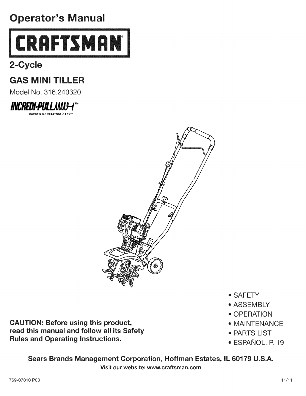
Operator's Manual
CRRFTSMRIq
2-Cycle
GAS MINI TILLER
Model No. 316.240320
INCREDI.PULU AU-P
UNBELIEVABLE STARTING EA S E TM
• SAFETY
ASSEMBLY
OPERATION
CAUTION: Before using this product,
read this manual and foJJow aJJits Safety
RuJes and Operating instructions.
Sears Brands Management Corporation, Noffman Estates, IL 60179 U.S.A.
Visit our website: www.craftsman.com
769-07010 P00 11/11
MAINTENANCE
PARTS LIST
ESPANOL, R 19
TABLEOFCONTENTS
Safety............................................... 2
Warranty............................................. 5
KnowYourUnit........................................ 6
Specifications......................................... 6
Assembly............................................. 7
OilandFuel........................................... 8
StartingandStopping................................... 9
Operation............................................ 10
Maintenance......................................... 11
CleaningandStorage.................................. 13
Troubleshooting....................................... 14
RepairProtectionAgreements........................... 15
PartsList............................................ 38
ServiceNumbers.............................. BackCover
Allinformation,illustrationsandspecificationsinthismanualarebased
onthelatestproductinformationavailableatthetimeofprinting.We
reservetherighttomakechangesatanytimewithoutnotice.
Thepurposeofsafetysymbolsistoattractyourattentionto
possibledangers.Thesafetysymbols,andtheirexplanations,
deserveyourcarefulattentionandunderstanding.Thesafety
warningsdonotbythemselveseliminateanydanger.The
instructionsorwarningstheygivearenotsubstitutesforproper
accidentpreventionmeasures.
SYMBOL MEANING
DANGER: Signals an EXTREME hazard.
Failure to obey a safety DANGER signal WILL result in
serious injury or death to yourself or to others.
WARNING: Signals a SERIOUS hazard.
Failure to obey a safety WARNING signal CAN result in
serious injury to yourself or to others.
CAUTION: Signals a MODERATE hazard.
Failure to obey a safety CAUTION signal MAY result in
property damage or injury to yourself or to others.
NOTE: Advises you of information or instructions vital to the
operation or maintenance of the equipment.
SPARK ARRESTOR NOTE
NOTE: For users on U.S. Forest Land and in the states of
California, Maine, Oregon and Washington. All U.S. Forest Land
and the state of California (Public Resources Codes 4442 and
4443), Oregon and Washington require, by law that certain internal
combustion engines operated on forest brush and/or grass-covered
areas be equipped with a spark arrestor, maintained in effective
working order, or the engine be constructed, equipped and
maintained for the prevention of fire. Check with your state or local
authorities for regulations pertaining to these requirements. Failure
to follow these requirements could subject you to liability or a fine.
This unit is factory equipped with a spark arrestor. Replacement
requires Muffler Assembly Part #753-06792, installed at a Sears
Parts & Repair Service Center.
CALIFORNIA PROPOSITION 65
WARNING: Engine exhaust, some of its constituents and
certain finished components contain or emit chemicals known
to the State of California to cause cancer and birth defects or
other reproductive harm. Wash hands after handling.
Read the operator's manual and follow all warnings and safety
instructions. Failure to do so can result in serious injury to the
operator and/or bystanders.
READ ALL iNSTRUCTiONS BEFORE OPERATING
WARNING: When using the unit, all safety rules must be
followed. Please read these instructions before operating
the unit in order to ensure the safety of the operator and any
bystanders. Please keep these instructions for later use.
o
Read the instructions carefully. Be familiar with the controls and
proper use of the unit.
o
Do not operate this unit when tired, ill or under the influence of
alcohol, drugs or medication.
o
Children and teens under the age of 15 must not use the unit,
except for teens guided by an adult.
o
All guards and safety attachments must be installed properly
before operating the unit.
o
Inspect the unit before use. Replace damaged parts. Check for
fuel leaks. Make sure all fasteners are in place and secure.
Replace parts that are cracked, chipped, or damaged in any
way. Do not operate the unit with loose or damaged parts.
o
Carefully inspect the area before starting the unit. Remove all
debris and hard or sharp objects such as glass, wire, etc.
o
Be aware of the risk of injury to the head, hands and feet.
o
Clear the area of children, bystanders and pets; keep them
outside a 50-foot (15 m) radius, at a minimum. Even then, they
are still at risk from thrown objects. Encourage bystanders to
wear eye protection. If you are approached, stop the unit
immediately.
Squeeze the throttle control and check that it returns
automatically to the idle position. Make all adjustments or
repairs before using the unit.
SAFETY WARNINGS FOR GAS UNITS
_WARNING: Gasoline is highly flammable and its vapors j
• Store fuel only in containers specifically designed and approved
can explode if ignited.Takethe following precautions:
for the storage of such materials.
Always stop the engine and allow it to cool before filling the
tank. Never remove the fuel tank cap or add fuel when the
engine is hot. Always loosen the fuel tank cap slowly to relieve
any pressure in the tank before fueling.
Always mix and add fuel in a clean, well-ventilated outdoor area
where there are no sparks or flames. DO NOT smoke.
Never operate the unit without the fuel cap securely in place.
Avoid creating a source of ignition for spilled fuel. Wipe up any
spilled fuel from the unit immediately, before starting the unit.
Move the unit at least 30 ft. (9.1 m) from the fueling source and
site before starting the engine. DO NOT smoke.
Never start or run the unit inside a closed room or building.
Breathing exhaust fumes can kill. Operate this unit only in a well
ventilated outdoor area.
WHILE OPERATING
Wear safety glasses or goggles that meet ANSi Z87.1-1989
standards and are marked as such. Wear ear/hearing protection
when operating this unit. Wear a face or dust mask if the
operation is dusty.
Wear heavy long pants, boots, gloves and a long sleeve shirt. Do
not wear loose clothing, jewelry, short pants, sandals or go
barefoot. Secure hair above shoulder level.
This unit has a clutch. The tines remain stationary when the
engine is idling. If they do not, take the unit to a Sears or other
qualified service dealer for an adjustment.
Be sure the tines are not in contact with anything before starting
the unit.
Use the unit only in daylight or good artificial light.
Avoid accidental starting. Be in the starting position whenever
pulling the starter rope. The operator and unit must be in a stable
position while starting. Refer to Starting and Stopping.
Use the right tool. Only use this tool for its intended purpose.
Use extreme caution when reversing or pulling the unit towards you.
Do not overreach. Always keep proper footing and balance. Take
extra care when working on steep slopes or inclines.
Always hold the unit with both hands when operating. Keep a
firm grip on both handles or grips.
Keep hands, face, and feet away from all moving parts. Do not
touch or try to stop the tines when they are rotating.
Do not touch the engine or muffler. These parts get extremely hot
from operation, even after the unit is turned off.
Do not operate the engine faster than the speed needed to cultivate.
Do not run the engine at high speed when you are not cultivating.
Always stop the engine when cultivating is delayed or when walking
from one cultivating location to another.
If you strike or become entangled with a foreign object, stop the
engine immediately and check for damage. Do not operate
before repairing damage. Do not operate the unit with loose or
damaged parts.
Turn the engine to off and disconnect the spark plug for
maintenance or repair.
Use only original equipment manufacturer (OEM) replacement
parts and accessories for this unit, as listed in the Parts List
section of this manual. Use of any other parts or accessories
could lead to serious injury to the user, or damage to the unit,
and void the warranty.
Keep the unit clean of vegetation and other materials that may
become lodged between the tines and guard.
To reduce fire hazard, replace a faulty muffler and spark arrestor.
Keep the engine and muffler free from grass, leaves, excessive
grease or carbon build up.
OTHER SAFETY WARNINGS
Never store the unit with fuel in the tank, inside a building where
fumes may reach an open flame (pilot lights, etc.) or sparks
(switches, electrical motors, etc.).
Allow the engine to cool before storing or transporting. Be sure
to secure the unit while transporting.
Store the unit in a dry place, secured or at a height to prevent
unauthorized use or damage. Keep out of the reach of children.
Never douse or squirt the unit with water or any other liquid.
Keep handles dry, clean and free from debris. Clean after each
use, see Cleaning and Storage instructions.
Clean tines with a household cleaner to remove any gum
buildup. Oil the tines with machine oil to prevent rust.
Keep these instructions. Refer to them often and use them to
instruct other users. If you loan this unit to others, also loan
them these instructions.
SAVE THESE iNSTRUCTiONS
3
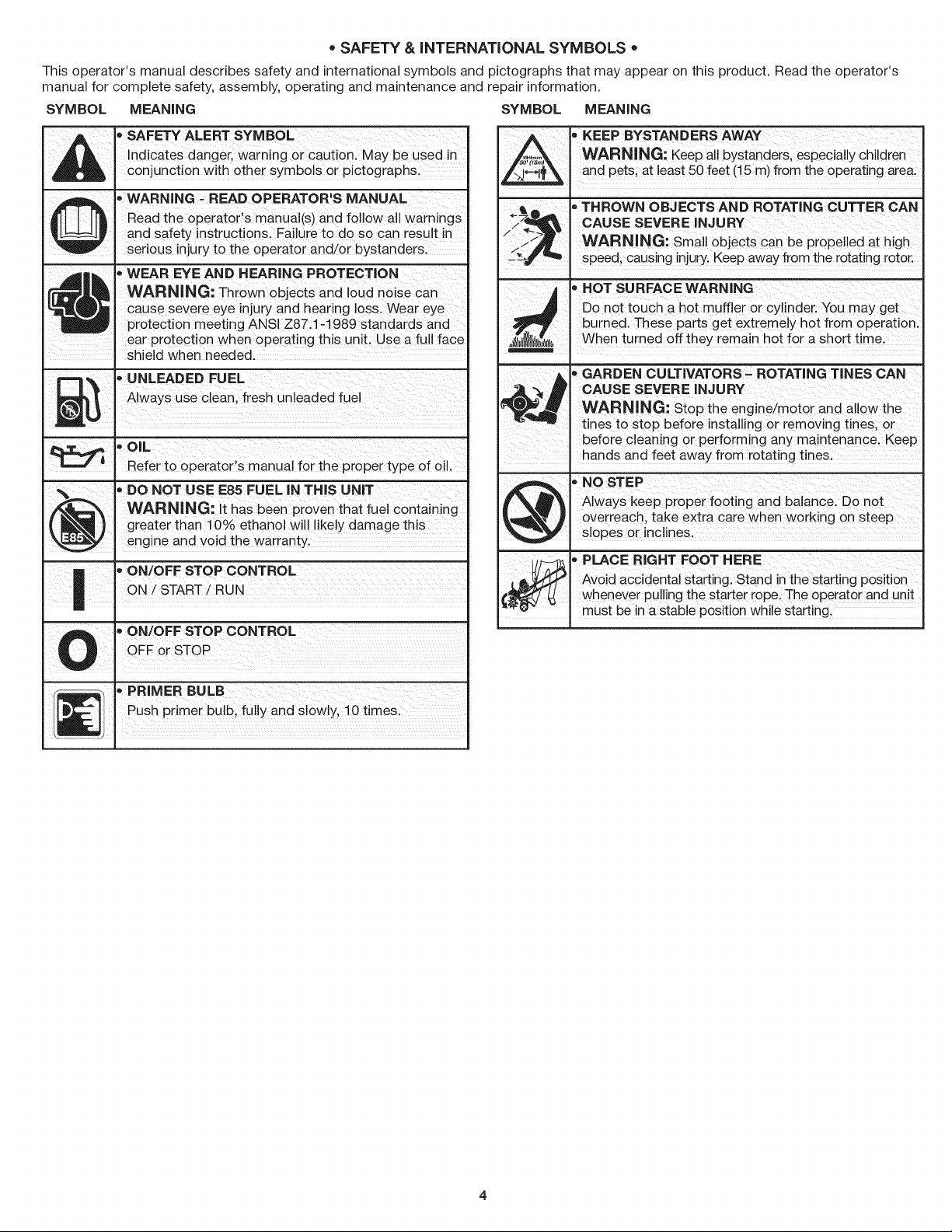
o SAFETY & iNTERNATiONAL SYMBOLS o
This operator's manual describes safety and international symbols and pictographs that may appear on this product. Read the operator's
manual for complete safety, assembly, operating and maintenance and repair information.
SYMBOL MEANING SYMBOL MEANING
_ • SAFETY ALERT SYMBOL
_]J J J[_ Read the operator's manual(s) and follow all warnings
4t _ - WEAR EYE AND HEARING PROTECTION
_! cause severe eye injury and hearing loss. Wear eye
m _ • UNLEADED FUEL
Indicates danger, warning or caution. May be used in
conjunction with other symbols or pictographs.
'_ WARNING - READ OPERATOR'S MANUAL
and safety instructions. Failure to do so can result in
serious injury to the operator and/or bystanders.
WARNING: Thrown objects and loud noise can
protection meeting ANSI Z87.1-1989 standards and
. ear protection when operating this unit. Use a full face
shield when needed.
_ Always use clean fresh unleaded fuel
.aUl
OIL
Refer to operator's manual for the proper type of oil.
• DO NOT USE E85 FUEL iN THIS UNiT
/_ I WARNING: It has been proven that fuel containing
(_ I greater than 10% ethanol will likely damage this
\_ I engine and void the warranty.
| I"ON/OFFSTOPCONTROL
| I
• ON/OFF STOP CONTROL
U . OgForSTOP
WARNING: Keep aii bystanders, espeCiallY Chi!dien
, EEP BYSTANDERS AWAY
and Pets, at least 50 feet (!5 m) from the operating area.
_71_ _THROWN OBJECTS AND ROTATING CUTTER CAN
/ :-_L_ CAUSE SEVERE INJURY
_< WARNING: small objects can be pr0peiied at high
speed, causing injury,Keep away from the rotating rotor.
, H0T SURFACE WARNING
Don0t touch a hot muffler or cyl!nder;You may get
burned. These parts get extremely hot from operation.
;_lllll/ll_l_ll),. When turned off they remain hot for a short t me.
_GARDEN CULTIVATORS _ ROTATING TINES CAN
CAUSE SEVERE iNJURY
WARNING: St0p the engine/m0t0r and
tines to stop before installing Or removing tines, or
before cleaning Or performing any maintenancel Keep
hands and feet away from rotating tines;
AlwaYS keep proper footing and balance: DO not
@ _ NOSTEP
Overreach, take extra care when working on Steep
slopes or inclines.
, PLACER GHTFooTHERE
[ __-! _ Avoid accidental starting. Stand in the starting position
€_ whenever pulling the starter rope: The operator and Unit
"_'_- . must be in a stable position while starting.
_ PRIMER BULB
_] Push prmerbulb fu yandsowly 10tmes
CRAFTSMANTWO YEAR FULL WARRANTY
FOR TWO YEARS from the date of purchase, this product is warranted against any defects in material or workmanship. A defective product
will receive free repair or replacement if repair is unavailable.
For warranty coverage details to obtain free repair or replacement, visit the web site: www.craftsman.com
This warranty covers ONLY defects in material and workmanship. Warranty coverage does NOT include:
• Expendable items that can wear out from normal use within the warranty period, such as blades, tines or belts.
Product damage resulting from user attempts at product modification or repair or caused by product accessories.
Repairs necessary because of accident or failure to operate or maintain the product according to all supplied instructions.
Preventive maintenance, or repairs necessary due to improper fuel mixture, contaminated or stale fuel.
This warranty is void if this product is ever used while providing commercial services or if rented to another person.
This warranty gives you specific legal rights, and you may also have other rights which vary from state to state.
Sears Brands Management Corporation, Hoffman Estates, IL 60179
FOR IN-WARRANTY SAFETY, OPERATION OR MAINTENANCE QUESTIONS, OR TO ORDER PARTS AND SCHEDULE
SERVICE, CALL 1=800=4=MY=HOME®.
5
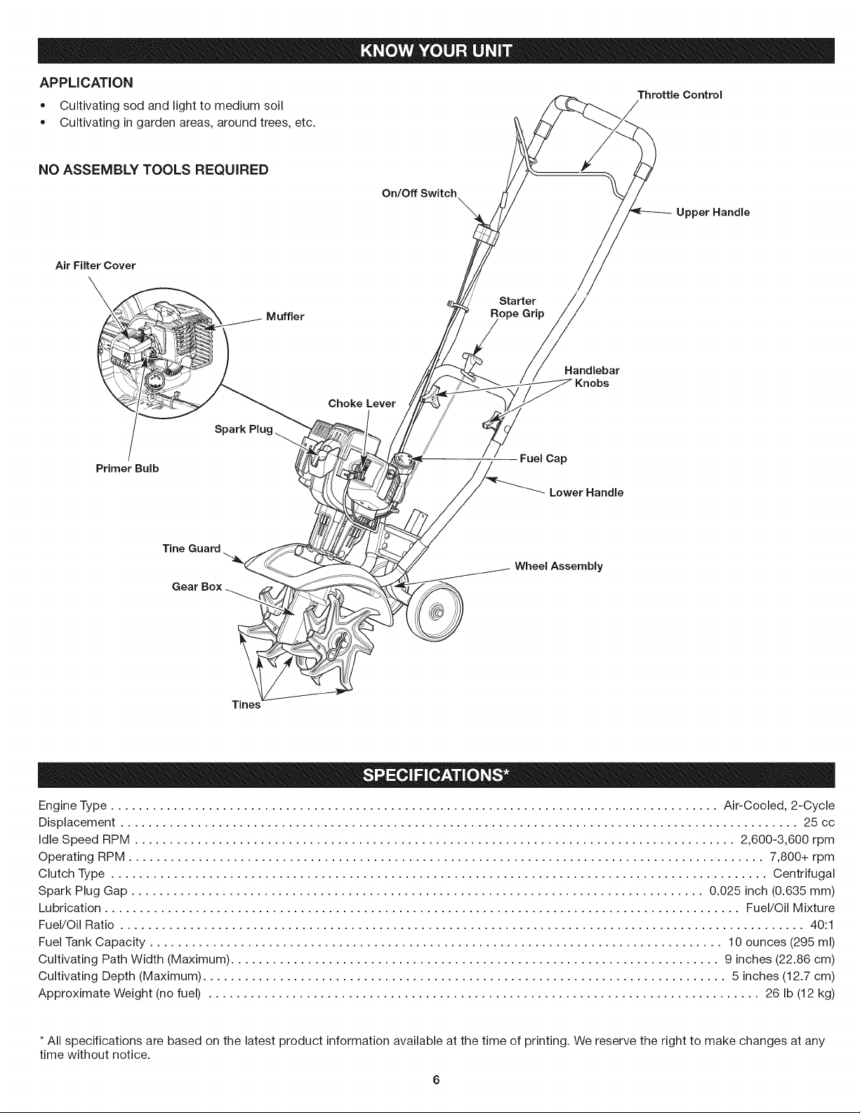
APPLiCATiON
• Cultivating sod and light to medium soil
Cultivating in garden areas, around trees, etc.
NO ASSEMBLY TOOLS REQUIRED
Air Filter Cover
Throttle Control
On/Off Switch
Upper Handle
Starter
Muffler ope Grip
Handlebar
Knobs
Choke Lever
Primer Bulb
Tine Guard
Tines
FueICap
LowerHandle
Wheel Assembly
Engine Type ....................................................................................... Air-Cooled, 2-Cycle
Displacement ................................................................................................. 25 cc
Idle Speed RPM ...................................................................................... 2,600-3,600 rpm
Operating RPM ........................................................................................... 7,800+ rpm
Clutch Type .............................................................................................. Centrifugal
Spark Plug Gap .................................................................................. 0.025 inch (0.635 mm)
Lubrication ........................................................................................... Fuel/Oil Mixture
Fuel/Oil Ratio .................................................................................................. 40:1
Fuel Tank Capacity .................................................................................. 10 ounces (295 ml)
Cultivating Path Width (Maximum) ...................................................................... 9 inches (22.86 cm)
Cultivating Depth (Maximum) ........................................................................... 5 inches (12.7 cm)
Approximate Weight (no fuel) ............................................................................... 26 Ib (12 kg)
* All specifications are based on the latest product information available at the time of printing. We reserve the right to make changes at any
time without notice.
ASSEMBLINGTHE UNiT _-.'_
Begin by carefully unpacking the contents and making sure that
nothing is damaged.
INSTALLING AND ADJUSTING THE WHEEL ASSEMBLY
_ WARNING: To prevent serious personal injury, the wheelj
assembly must be installed when operating the unit.
gloves and a long sleeve shirt when installing the wheel
WARNING: To avoid injury from the tines, wear heavy
assembly.
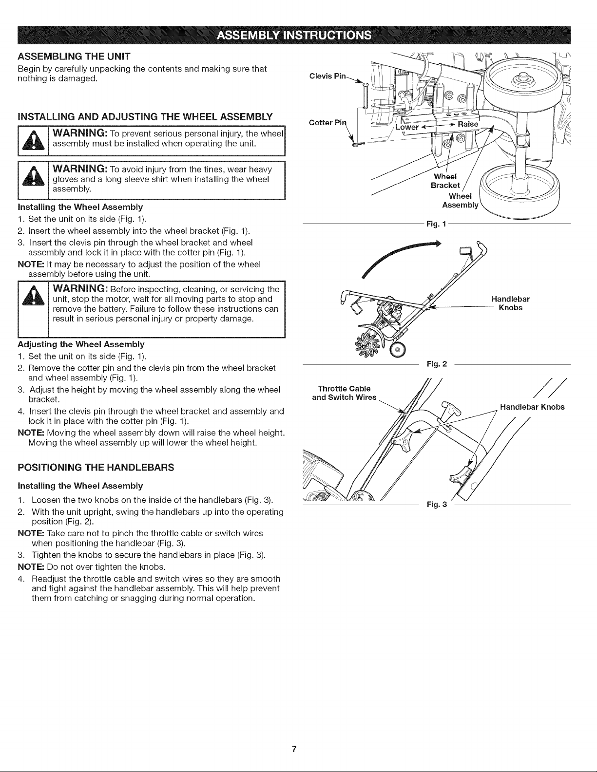
Installing the Wheel Assembly
1. Set the unit on its side (Fig. 1).
2. Insert the wheel assembly into the wheel bracket (Fig. 1).
3. Insert the clevis pin through the wheel bracket and wheel
assembly and lock it in place with the cotter pin (Fig. 1).
NOTE: It may be necessary to adjust the position of the wheel
assembly before using the unit.
unit, stop the motor, wait for all moving parts to stop and
remove the battery. Failure to follow these instructions can
result in serious personal injury or property damage.
WARNING: Before inspecting, cleaning, or servicing the
Adjusting the Wheel Assembly
1. Set the unit on its side (Fig. 1).
2. Remove the cotter pin and the clevis pin from the wheel bracket
and wheel assembly (Fig. 1).
3. Adjust the height by moving the wheel assembly along the wheel
bracket.
4. Insert the clevis pin through the wheel bracket and assembly and
lock it in place with the cotter pin (Fig. 1).
NOTE: Moving the wheel assembly down will raise the wheel height.
Moving the wheel assembly up will lower the wheel height.
Cotter Pir_
Wheel
Bracket
Wheel
Assembb
Fig. 1
Handlebar
Knobs
Fig. 2
Throttle Cable
and Switch Wires
Handlebar Knobs
POSiTiONiNG THE HANDLEBARS
installing the Wheel Assembly
1. Loosen the two knobs on the inside of the handlebars (Fig. 3).
2. With the unit upright, swing the handlebars up into the operating
position (Fig. 2).
NOTE: Take care not to pinch the throttle cable or switch wires
when positioning the handlebar (Fig. 3).
3. Tighten the knobs to secure the handlebars in place (Fig. 3).
NOTE: Do not over tighten the knobs.
4. Readjust the throttle cable and switch wires so they are smooth
and tight against the handlebar assembly. This will help prevent
them from catching or snagging during normal operation.
Fig. 3
OiL AND FUEL MiXiNG iNSTRUCTiONS
The use of old and/or improperly mixed fuel is the most common cause
of performance problems. Use only fresh, clean unleaded gasoline.
Follow the instructions carefully for the proper gasoline/oil mixture.
Definition of Blended Fuels
Today's fuels are often a blend of gasoline and oxygenates such as
ethanol, methanol or MTBE (ether). Alcohol-blended fuel absorbs
water. As little as 1% water in the fuel can make fuel and oil
separate, forming acids when stored. ALWAYS use fresh fuel (less
than 30 days old).
NOTE: Dispose of old fuel according to federal, state and local
regulations.
Using Blended Fuels
If using a blended fuel:
• Always use the fresh fuel mix explained in your operator's manual
Use the fuel additive STA-BIL® or an equivalent
Always agitate the fuel mix before fueling the unit
Drain the tank and run the engine dry before storing the unit
_ WARNING: DO NOT USE E85 FUEL IN THiS UNIT. It |
Using Fuel Additives
The bottle of 2-cycle oil provided with this unit contains a fuel
additive to help inhibit corrosion and minimize gum deposits.
Always use the brand of 2-cycle oil that came with this unit. Ifthis is
unavailable, use a 2-cycle oil designed for air-cooled engines and
mix it with a fuel additive, such as STA-BIL Fuel Stabilizer or an
equivalent. Add 0.8 oz. (23 ml) of fuel additive per gallon of fuel,
according to the instructions on the container. NEVER add fuel
additives directly to the unit's fuel tank.
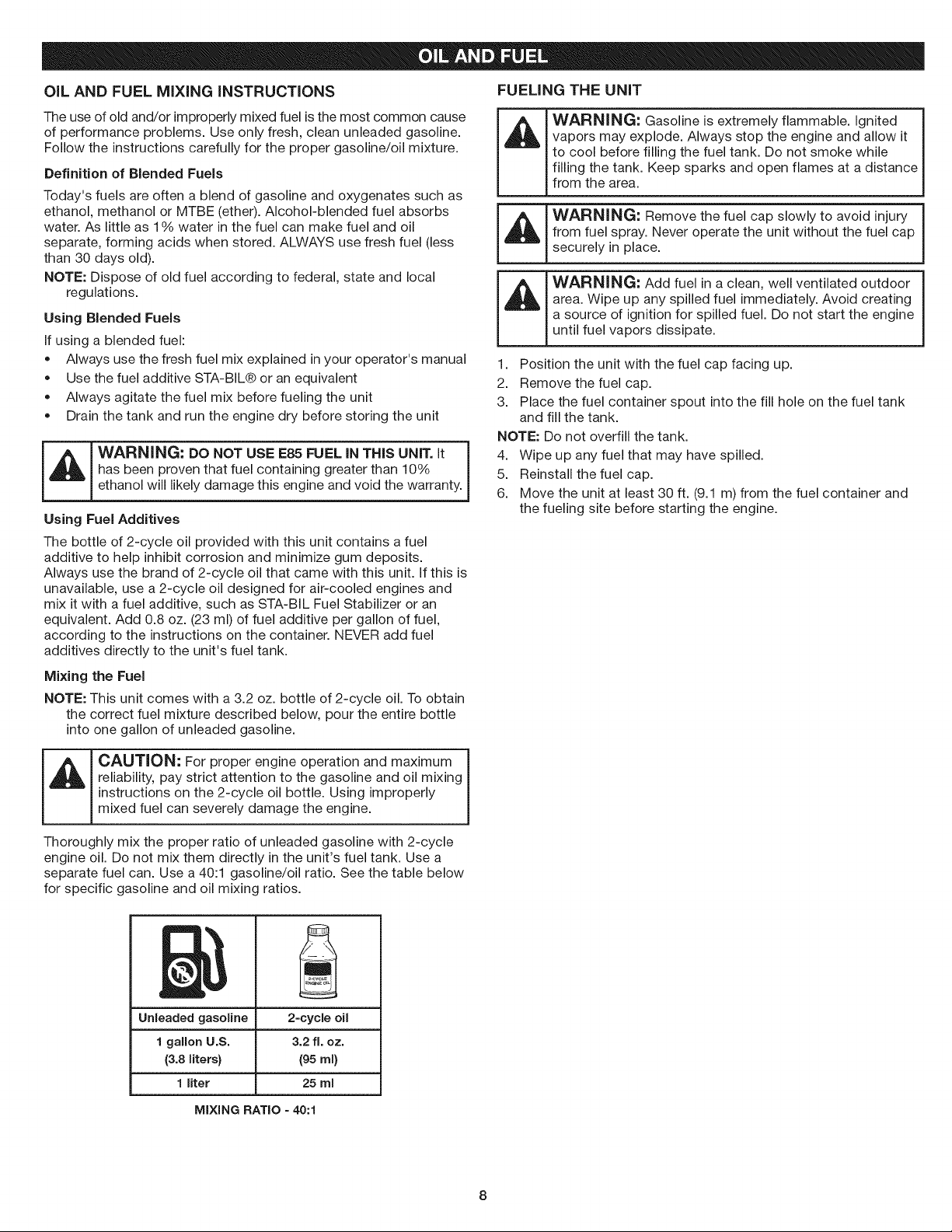
Mixing the Fuel
NOTE: This unit comes with a 3.2 oz. bottle of 2-cycle oil. To obtain
has been proven that fuel containing greater than 10%
ethanol will likely damage this engine and void the warranty.
the correct fuel mixture described below, pour the entire bottle
into one gallon of unleaded gasoline.
FUELING THE UNiT
WARNING: Gasoline is extremely flammable. Ignited
vapors may explode. Always stop the engine and allow it
to cool before filling the fuel tank. Do not smoke while
filling the tank. Keep sparks and open flames at a distance
from the area.
WARNING: Remove the fuel cap slowly to avoid injury
from fuel spray. Never operate the unit without the fuel cap
securely in place.
WARNING: Add fuel in a clean, well ventilated outdoor
area. Wipe up any spilled fuel immediately. Avoid creating
a source of ignition for spilled fuel. Do not start the engine
until fuel vapors dissipate.
1. Position the unit with the fuel cap facing up.
2. Remove the fuel cap.
3. Place the fuel container spout into the fill hole on the fuel tank
and fill the tank.
NOTE: Do not overfill the tank.
I
4. Wipe up any fuel that may have spilled.
5. Reinstall the fuel cap.
1
6. Move the unit at least 30 ft. (9.1 m) from the fuel container and
the fueling site before starting the engine.
CAUTION: For proper engine operation and maximum
reliability, pay strict attention to the gasoline and oil mixing
instructions on the 2-cycle oil bottle. Using improperly
mixed fuel can severely damage the engine.
Thoroughly mix the proper ratio of unleaded gasoline with 2-cycle
engine oil. Do not mix them directly in the unit's fuel tank. Use a
separate fuel can. Use a 40:1 gasoline/oil ratio. See the table below
for specific gasoline and oil mixing ratios.
Unleaded gasoline
1 gallon U.S.
(3.8liters}
1 liter
MIXING RATIO =40:1
2=cycleoil
3.2 ft. oz.
(95ml)
25 rnl
outdoor area. Carbon monoxide exhaust fumes can be
I_IL IWARNING: Operate this unit only in a well-ventilated
lethal in a confined area.
!
Throttle Control
Stop/Off (O)
On/Off Switch
_L_____[ ARNING: Avoid accidentally starting the unit. To avoid
STARTING INSTRUCTIONS
1. Mix gasoline with oil. Refer to Oil and Fuel Mixing Instructions.
2. Fill the fuel tank. Refer to Fueling the Unit.
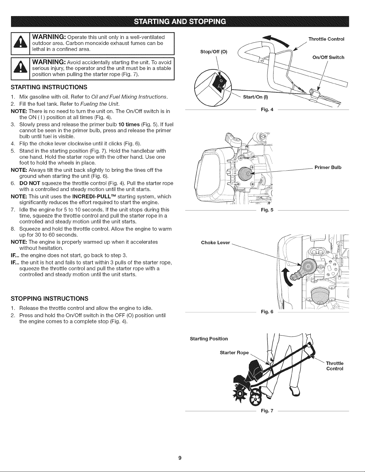
NOTE: There is no need to turn the unit on. The On/Off switch is in
3. Slowly press and release the primer bulb 10 times (Fig. 5). If fuel
4. Flip the choke lever clockwise until it clicks (Fig. 6).
5. Stand in the starting position (Fig. 7). Hold the handlebar with
NOTE: Always tilt the unit back slightly to bring the tines off the
6. DO NOT squeeze the throttle control (Fig. 4). Pull the starter rope
NOTE: This unit uses the INCREDI-PULL TM starting system, which
7. Idle the engine for 5 to 10 seconds. If the unit stops during this
8. Squeeze and hold the throttle control. Allow the engine to warm
NOTE: The engine is properly warmed up when it accelerates
IF... the engine does not start, go back to step 3.
IF... the unit is hot and fails to start within 3 pulls of the starter rope,
serious injury, the operator and the unit must be in a stable
position when pulling the starter rope (Fig. 7).
the ON (I) position at all times (Fig. 4).
cannot be seen in the primer bulb, press and release the primer
bulb until fuel is visible.
one hand. Hold the starter rope with the other hand. Use one
foot to hold the wheels in place.
ground when starting the unit (Fig. 6).
with a controlled and steady motion until the unit starts.
significantly reduces the effort required to start the engine.
time, squeeze the throttle control and pull the starter rope in a
controlled and steady motion until the unit starts.
up for 30 to 60 seconds.
without hesitation.
squeeze the throttle control and pull the starter rope with a
controlled and steady motion until the unit starts.
J
Start/On (I)
Fig.4
Primer Bulb
Fig. 5
Choke Lever
STOPPING INSTRUCTIONS
1. Release the throttle control and allow the engine to idle.
2. Press and hold the On/Off switch in the OFF (O) position until
the engine comes to a complete stop (Fig. 4).
Fig. 6
Starting Position
Starter Ro
Throttle
Control
Fig. 7
9
WARNING: Dress properly to reduce the risk of injury
when operating this unit. Do not wear loose clothing or
jewelry. Wear eye and ear/hearing protection. Wear heavy
long pants, boots and gloves. Do not wear short pants,
sandals or operate barefoot.
OPERATING TiPS
1. Move the cultivator to the work area prior to starting the engine.
Refer to Moving the Unit.
L_J AUTION: To prevent serious personal injury, never
2. Start the unit as described in the Starting Instructions.
3. With the tines off the ground, squeeze the throttle control to
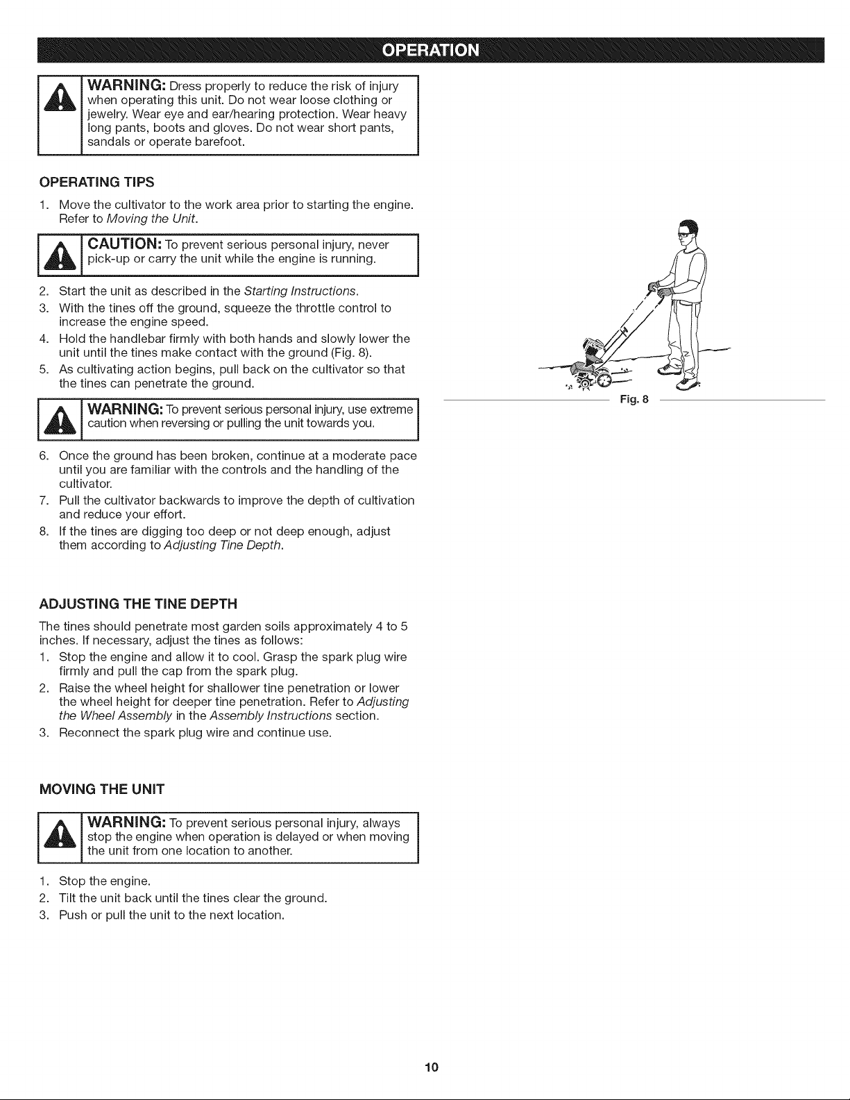
4. Hold the handlebar firmly with both hands and slowly lower the
5. As cultivating action begins, pull back on the cultivator so that
_ ARNING: To prevent serious personal injury,use extreme
6. Once the ground has been broken, continue at a moderate pace
7.
8.
pick-up or carry the unit while the engine is running.
increase the engine speed.
unit until the tines make contact with the ground (Fig. 8).
the tines can penetrate the ground.
caution when reversing or pulling the unit towards you.
until you are familiar with the controls and the handling of the
cultivator.
Pull the cultivator backwards to improve the depth of cultivation
and reduce your effort.
If the tines are digging too deep or not deep enough, adjust
them according to Adjusting -FineDepth.
ADJUSTING THE TINE DEPTH
The tines should penetrate most garden soils approximately 4 to 5
inches. If necessary, adjust the tines as follows:
1. Stop the engine and allow it to cool. Grasp the spark plug wire
firmly and pull the cap from the spark plug.
2. Raise the wheel height for shallower tine penetration or lower
the wheel height for deeper tine penetration. Refer to Adjusting
the Wheel Assembly in the Assembly Instructions section.
3. Reconnect the spark plug wire and continue use.
]
Fig. 8
J
MOVING THE UNiT
stop the engine when operation is delayed or when moving
the unit from one location to another.
1. Stop the engine.
2. Tilt the unit back until the tines clear the ground.
3. Push or pull the unit to the next location.
10
WARNING: To prevent serious injury, never perform
maintenance or repairs while the unit is running. Always
allow the unit to cool before servicing or repairing the unit.
Disconnect the spark plug wire to prevent the unit from
starting accidentally.
MAINTENANCE SCHEDULE
Perform these required maintenance procedures at the frequency
stated in the table. These procedures should also be a part of any
seasonal tune-up.
NOTE: Some maintenance procedures may require special tools or
skills. If unsure about these procedures, take the unit to a Sears
or other qualified service dealer. Call 1-800-4-MY-HOME for
more information.
NOTE: Maintenance, replacement, or repair of the emission control
devices and system may be performed by a Sears or other qualified
service dealer. Call 1=800-4-MY-HOME for more information.
NOTE: Please read the California/EPA statement that came with the
unit for a complete listing of terms and coverage for the
emissions control devices, such as the spark arrestor, muffler,
carburetor, etc.
FREQUENCY MAINTENANCE REQUIRED
Every 10 hours Clean and re-oil the air filter. Refer to
Maintaining the Air Filter.
Every 25 hours Check the spark plug condition and gap. Refer
to Maintaining the Spark Plug.
TINE REMOVAL AND REPLACEMENT
__ l WARNJNG: To prevent serious personal injury, always j
wear heavy gloves when handling the tines.
NOTE: All installation instructions are explained from the operating
position.
All 4 tines should be replaced at the same time because they will
wear evenly through normal use. Work on one side at a time.
1. Stop the engine and allow it to cool. Grasp the spark plug wire
firmly and pull the cap from the spark plug.
2. Lay the cultivator back on a flat level surface with the handles
touching the ground so that the cultivator is in a horizontal position.
NOTE: It may be necessary to wash any dirt off the tines and shaft
for easier tine removal.
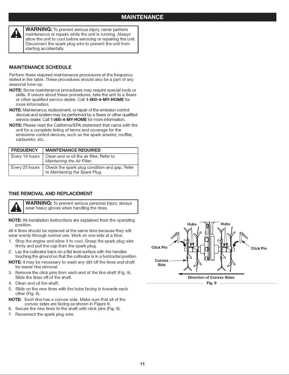
3. Remove the click pins from each end of the tine shaft (Fig. 9).
Slide the tines off of the shaft.
4. Clean and oil the shaft.
5. Slide on the new tines with the hubs facing in towards each
other (Fig. 9).
NOTE: Each tine has a convex side. Make sure that all of the
convex sides are facing as shown in Figure 9.
6. Secure the new tines to the shaft with click pins (Fig. 9).
7. Reconnect the spark plug wire.
Click Pin
Convex
Side
Hubs
' Hubs
Direction of Convex Sides
Fig. 9
Click Pin
11
AiR FILTER MAINTENANCE
Cleaning the Air Filter
Failure to maintain your air filter properly can result in poor
performance or can cause permanent damage to your engine.
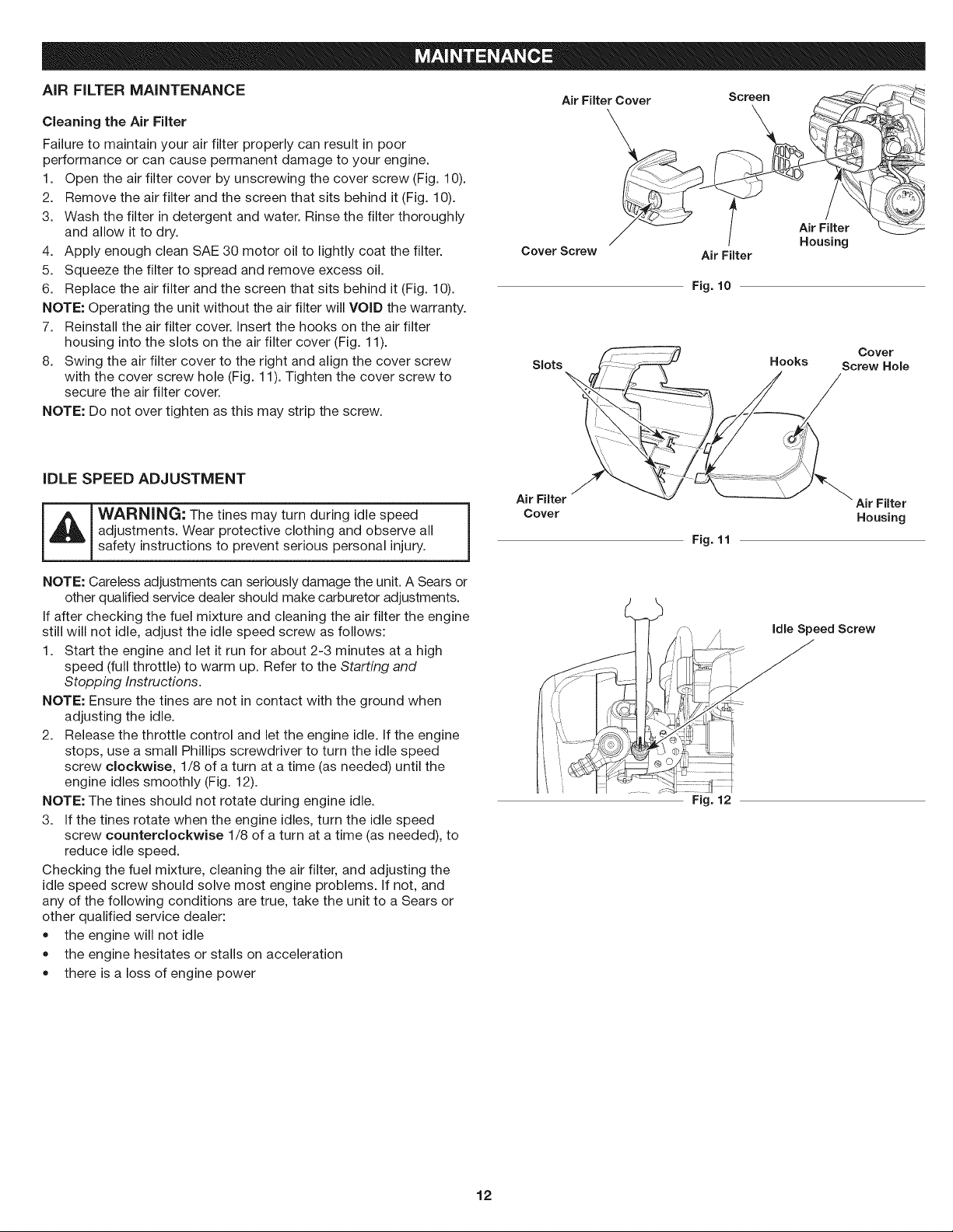
1. Open the air filter cover by unscrewing the cover screw (Fig. 10).
2. Remove the air filter and the screen that sits behind it (Fig. 10).
3. Wash the filter in detergent and water. Rinse the filter thoroughly
and allow it to dry.
4. Apply enough clean SAE 30 motor oil to lightly coat the filter.
5. Squeeze the filter to spread and remove excess oil.
6. Replace the air filter and the screen that sits behind it (Fig. 10).
NOTE: Operating the unit without the air filter will VOiD the warranty.
7. Reinstall the air filter cover, insert the hooks on the air filter
housing into the slots on the air filter cover (Fig. 11).
8. Swing the air filter cover to the right and align the cover screw
with the cover screw hole (Fig. 11). Tighten the cover screw to
secure the air filter cover.
NOTE: Do not over tighten as this may strip the screw.
Cover Screw Air Filter
Slots
iDLE SPEED ADJUSTMENT
Air Filter
_ WARNING: The tines may turn during idle speed _ Cover
adjustments. Wear protective clothing and observe all
safety instructions to prevent serious personal injury.
1
Air Filter Cover
\
Fig. 10
Fig. 11
Screen
/
Air Filter
Housing
Hooks Screw Hole
Cover
Air Filter
Housing
NOTE: Careless adjustments can seriously damage the unit. A Sears or
other qualified service dealer should make carburetor adjustments.
If after checking the fuel mixture and cleaning the air filter the engine
still will not idle, adjust the idle speed screw as follows:
1. Start the engine and let it run for about 2-3 minutes at a high
speed (full throttle) to warm up. Refer to the Starting and
Stopping Instructions.
NOTE: Ensure the tines are not in contact with the ground when
adjusting the idle.
2. Release the throttle control and let the engine idle. If the engine
stops, use a small Phillips screwdriver to turn the idle speed
screw clockwise, 1/8 of a turn at a time (as needed) until the
engine idles smoothly (Fig. 12).
NOTE: The tines should not rotate during engine idle.
3. If the tines rotate when the engine idles, turn the idle speed
screw counterclockwise 1/8 of a turn at a time (as needed), to
reduce idle speed.
Checking the fuel mixture, cleaning the air filter, and adjusting the
idle speed screw should solve most engine problems. If not, and
any of the following conditions are true, take the unit to a Sears or
other qualified service dealer:
• the engine will not idle
the engine hesitates or stalls on acceleration
there is a loss of engine power
Idle Speed Screw
Fig. 12
12
 Loading...