

Craftsman 315275110 Owner’s Manual
p
SW/A/ S
OWNER'S
MANUAL
MODEL NO.
i
n i
315.275110
CAUTION:
Read and follow
ALL safety rules
and instructions
before operating
this equipment.
I
I I
CRRFTSMRN°
Industrial Electronic
Plunge Router
Double Insulated
Warranty
Introduction
Unpacking
Features
Adjustments
Thank You for Buying
Craftsman Tools
Operation
Maintenance
®
Repair Parts
Sold by SEARS, ROEBUCK AND CO., Hoffman Estates, IL 60179 U.S.A.
972000-290 Printed In U.S.A.
10-00

RULES FOR SAFE OPERATION
DOUBLE INSULATION is a safety concept in electric
power tools which eliminates the need for the usual
three wire grounded power cord and grounded supply
system. Wherever there is electric current in the tool
there are two complete sets of insulation to protect the
user. All exposed metal parts are isolated from internal
metal motor components with protecting insulation.
WARNING:
READ ALL INSTRUCTIONS
1. KNOW YOUR POWER TOOL. Read owner's
manual carefully. Learn its applications and
limitations as well as the specific potential
hazards related to this tool.
2. GUARD AGAINST ELECTRICAL SHOCK
by preventing body contact with grounded
surfaces. For example: Pipes, radiators, ranges,
refrigerator enclosures.
3. KEEP GUARDS IN PLACE and in working
order.
4. KEEP WORK AREA CLEAN. Cluttered areas
and benches invite accidents.
5. AVOID DANGEROUS ENVIRONMENT.
Don't use power tool in damp or wet locations or
expose to rain, Keep work area well lit.
6. KEEP CHILDREN AND VISITORS AWAY.
All visitors should wear safety glasses and be
kept a safe distance from work area. Do not let
visitors contact tool or extension cord.
7. STORE IDLE TOOLS. When not in use tools
should be stored in a dry and high or locked-up
place - out of the reach of children.
8. DON'T FORCE TOOL. It will do the job better
and safer at the rate for which it was designed.
9. USE RIGHT TOOL. Don't force small tool or
attachment to do the job of a heavy duty tool.
Don't use tool for purpose not intended - for
example - A circular saw should never be used
for cutting tree limbs or logs.
10. WEAR PROPER APPAREL. Do not wear
loose clothing or jewelry that can get caught in
tool's moving parts and cause personal injury.
Rubber gloves and non-skid footwear are
IMPORTANT- Servicing of a tool with double insulation
requires extreme care and knowledge of the system
and should be performed only by a qualified service
technician. For service we suggest you return the tool
to your nearest Sears Store for repair. Always use
original factory replacement parts when servicing.
WARNING:
Do not attempt to operate this tool until you have
read thoroughly and understand completely all
instructions, safety rules, etc. contained in this
manual. Failure to comply can result in accidents
involving fire, electric shock, or serious personal
injury. Save owner's manual and review frequently
for continuing safe operation, and instructing others
who may use this tool.
recommended when working outdoors. Wear
protective hair covering to contain long hair and
keep itfrom being drawn into nearby air vents.
11. ALWAYS WEAR SAFETY GLASSES.
Everyday eyeglasses have only impact-resistant
lenses; they are NOT safety glasses.
12. PROTECT YOUR LUNGS. Wear a face or
dust mask if operation is dusty.
13. PROTECT YOUR HEARING. Wear hearing
protection during extended periods of operation.
14. DON'T ABUSE CORD. Never carry tool by
cord or yank it to disconnect from receptacle.
Keep cord from heat, oil and sharp edges.
15. SECURE WORK. Use clamps or a vise to hold
work. Both hands ar# needed to operate the
tool.
16. DON'T OVERREACH. Keep properfooting and
balance at all times. Do not use on a ladder or
unstable support.
17. MAINTAIN TOOLS WITH CARE. Keep tools
sharp at all times, and clean for best and safest
performance. Follow instructions for lubricating
and changing accessories.
18. DISCONNECT TOOLS. When not in use, be-
fore servicing, or when changing attachments,
blades, bits, cutters, etc., all tools should be
disconnected from power supply.
19. REMOVE ADJUSTING KEYS AND
WRENCHES. Form habit of checking to see
that keys and adjusting wrenches are removed
from tool before turning it on.
_k Look for this symbol to point out important safety precautions. ]
It means attention!!! Your safety is revolved.
Page 2
RULES FOR SAFE OPERATION (Continued)
20. AVOID ACCIDENTAL STARTING. Don't carry
plugged-in tools with finger on switch. Be sure
switch is off when plugging in.
21. MAKE SURE YOUR EXTENSION CORD IS
IN GOOD CONDITION. When usinganextension
cord, be sureto use one heavy enough to carrythe
currentyour productwilldraw. An undersized cord
willcause a drop in line voltage resulting in loss of
power and overheating. Awire gage size (A.W.G.)
of at least 14 is recommended for an extension
cord 25 feet or less in length.A cord exceeding 25
feet isnot recommended. If in doubt, use the next
heavier gage. The smal_r the gage number, the
heavier the cord.
22. OUTDOOR USE EXTENSION CORDS. When
tool is used outdoors, use only extension cords
suitablefor use outdoors.Outdoor approved cords
are marked with the suffix W-A, for example -
SJTW-A or SJOW-A.
23. KEEP CUTTERS CLEAN AND SHARP.
Sharp cutters minimize stalling and kickback.
24. KEEP HANDS AWAY FROM CUTTING
AREA. Keep hands away from cutters. Do not
reach underneath work while cutter is rotating.
Do not attempt to remove material while cutter is
rotating.
25. NEVER USE IN AN EXPLOSIVE
ATMOSPHERE. Normal sparking of the motor
could ignite fumes.
26. INSPECT TOOL CORDS PERIODICALLY
and if damaged, have repaired at your nearest
Sears Repair Center. Stay constantly aware of
cord location.
27. INSPECT EXTENSION CORDS PERIODI-
CALLY and replace if damaged.
28. KEEP HANDLES DRY, CLEAN, AND FREE
FROM OIL AND GREASE. Always use a clean
clothwhen cleaning. Never use brake fluids, gaso-
line, petroleum-based products or any strong sol-
vents to clean your tool.
29. STAY ALERT. Watch what you are doing and
use common sense. Do not operate tool when
you are tired. Do not rush.
30. CHECK DAMAGED PARTS. Before further
use of the tool, a guard or other part that is
damaged should be carefully checked to deter-
mine that it will operate properly and perform its
intended function. Check for alignment of moving
parts, binding of moving parts, breakage of parts,
mounting, and any other conditions that may af-
fect its operation. A guard or other part that is
damaged should be properly repaired or replaced
by an authorized service center unless indicated
elsewhere in this instruction manual.
31. DO NOT USE TOOL IF SWITCH DOES NOT
TURN IT ON AND OFF. Have defective
switches replaced by an authorized service cen-
ter.
32. INSPECT FOR and remove all nails from lumber
before routing.
33. DRUGS, ALCOHOL, MEDICATION. Do not
operate tool while under the influence of drugs,
alcohol, or any medication.
34. WHEN SERVICING USE ONLY IDENTICAL
CRAFTSMAN REPLACEMENT PARTS.
35. POLARIZED PLUGS. To reduce the risk of
electric shock, this tool has a polarized plug (one
blade is wider than the other). This plug willfit in a
polarized outlet only one way. If the plug does not
fit fully inthe outlet, reverse the plug. If itstill does
not fit, contact a qualified electrician to install the
proper outlet. Do not change the plugin any way.
36. DO NOT USE TOOL UNDER "BROWN-
OUT" OR OTHER LOW VOLTAGE CONDI-
TIONS. Also, do not use with any device that
could cause the power supply voltage to change.
37. WHEN USING THIS ROUTER WITH A
ROUTER TABLE, HELP PREVENT POS-
SIBLE SERIOUS INJURY BY KEEPING THE
CUTTER GUARDED AT ALL TIMES. Use
only router tables, with guards, that have been
designed for use on touters that are of this type,
size, and weight.
38. SAVE THESE INSTRUCTIONS. Review them
frequently and use them to instruct others who
may use this tool. If you loan someone this tool,
loan them these instructionsalso.
_t
WARNING:
Some dust created by power sanding, sawing, grinding,
drilling, and other construction activities contains
chemicals known to cause cancer, birth defects or
other reproductive harm. Some examples of these
chemicals are:
• lead from lead-based paints,
• crystalline silica from bricks and cement and other
masonry products, and
• arsenic and chromium from chemically-treated
lumber.
Your risk from these exposures varies, depending on
how often you do this type of work. To reduce your
exposure to these chemicals: work in a well ventilated
area, and work with approved safety equipment, such
as those dust masks that are specially designed to filter
out microscopic particles.
D_
INTRODUCTION
• CONGRATULATIONS AND THANK YOU FOR BUYING
THIS CRAFTSMAN ROUTER. it has been designed,
engineered and manufactured toprovide you withSears high
standard of dependability, ease of operation, and operator
safety. Properly cared for, it will give you years of rugged,
trouble-free performance.
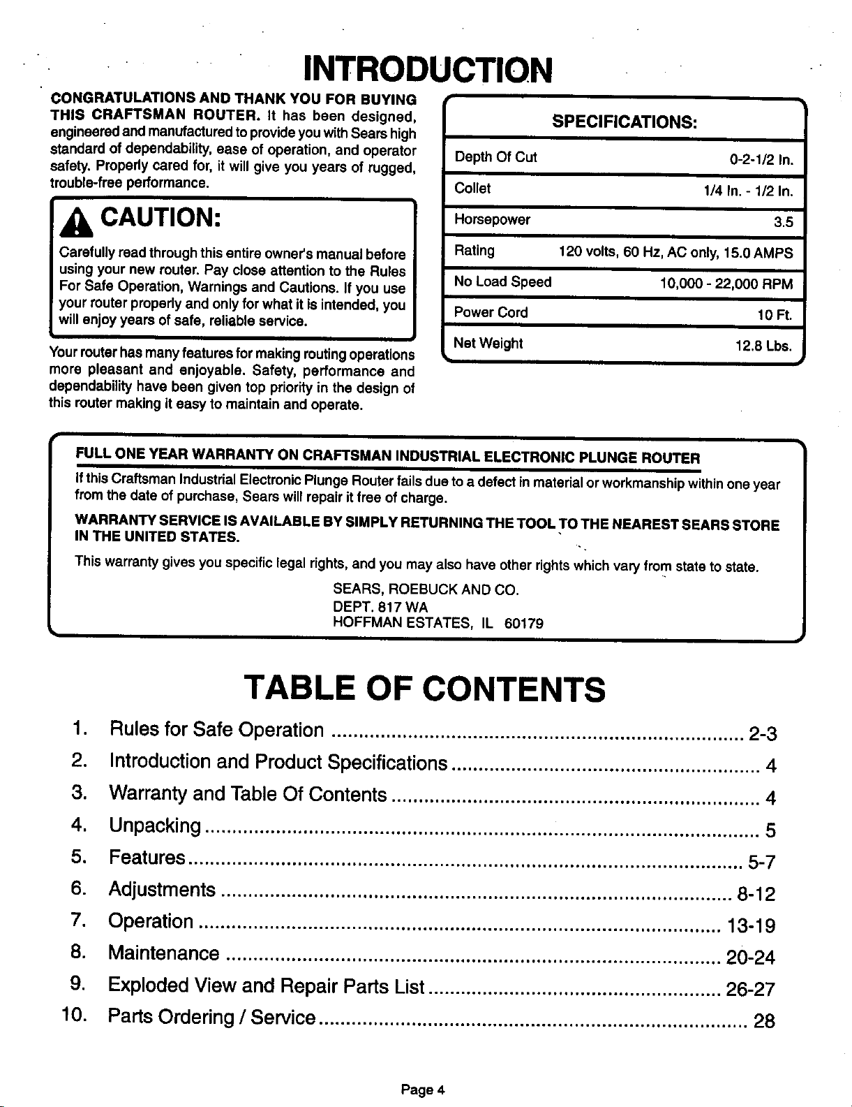
Depth Of Cut
Collet
SPECIFICATIONS:
0-2-1/2 In.
1/4 In. - 1/2 In.
CAUTION:
Carefully road through this entire owner's manual before
using your new router. Pay close attention to the Rules
For Safe Operation, Warnings and Cautions. if you use
your router properly and only for what it is intended, you
will enjoy years of safe, reliable service.
i
Your router has many features for making routing operations
more pleasant and enjoyable. Safety, performance and
dependability have been given top priority in the design of
this router making it easy to maintain and operate.
FULL ONE YEAR WARRANTY ON CRAFTSMAN INDUSTRIAL ELECTRONIC PLUNGE ROUTER
Ifthis Craftsman Industrial Electronic Plunge Router fails due to a defect in material or workmanship withinone year
from the date of purchase, Sears will repair itfree of charge.
WARRANTY SERVICE IS AVAILABLE BY SIMPLY RETURNING THE TOOL TO THE NEAREST SEARS STORE
IN THE UNITED STATES. ..
This warranty gives you specific legal rights, and you may also have other rights which vary from state to stats.
SEARS, ROEBUCK AND CO.
DEPT. 817 WA
HOFFMAN ESTATES, IL 60179
Horsepower
Rating
No Load Speed
Power Cord
Nat Weight
120 volts, 60 Hz, AC only, 15.0 AMPS
10,000 - 22,000 RPM
3.5
10Ft.
12.8 Lbs.
TABLE OF CONTENTS
1. Rules for Safe Operation ............................................................................ 2-3
2. Introductionand Product Specifications......................................................... 4
3. Warranty and Table Of Contents .................................................................... 4
4. Unpacking ...................................................................................................... 5
5. Features ...................................................................................................... 5-7
6. Adjustments .............................................................................................. 8-12
7. Operation ................................................................................................ 13-19
8. Maintenance ........................................................................................... 20-24
9. Exploded View and Repair Parts List...................................................... 26-27
10. Parts Ordering/Service ............................................................................... 28
P_e4
:UNPACKING
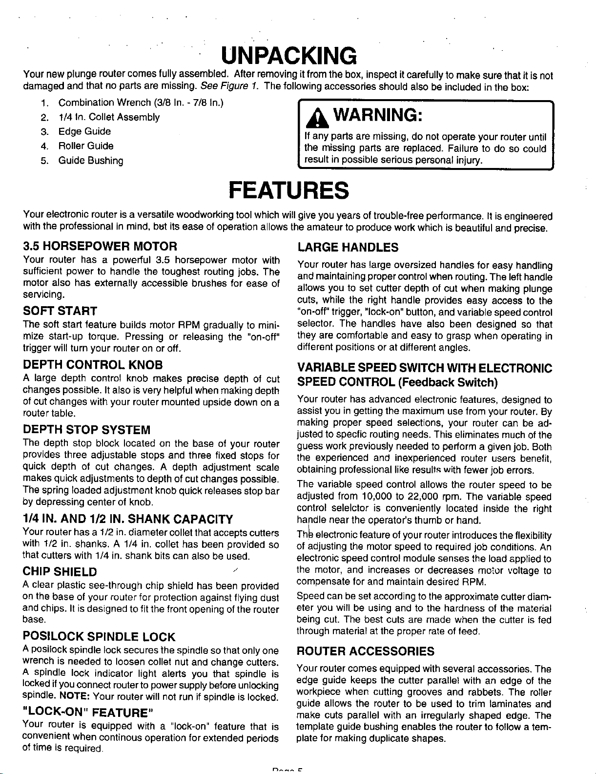
Your new plunge router comes fully assembled. After removing it from the box, inspect it carefully to make sure that itis not
damaged and that no parts are missing. See Figure 1. The following accessories should also be included in the box:
1. Combination Wrench (3/8 In. - 7/8 In.)
2. 1/4 In. Collet Assembly
3. Edge Guide
4. Roller Guide
5. Guide Bushing
FEATURES
Your electronic router is a versatile woodworking tool which will give you years of trouble-free performance. It is engineered
with the professional in mind, but its ease of operation allows the amateur to produce work which is beautiful and precise.
WARNING:
If any parts are missing, do not operate your router until
the missing parts are replaced. Failure to do so could
result in possible serious personal injury.
3.5 HORSEPOWER MOTOR
Your router has a powerful 3.5 horsepower motor with
sufficient power to handle the toughest routing jobs. The
motor also has externally accessible brushes for ease of
servicing.
SOFT START
The soft start feature builds motor RPM gradually to mini-
mize start-up torque. Pressing or releasing the "on-off"
trigger will turn your router on or off.
DEPTH CONTROL KNOB
A large depth control knob makes precise depth of cut
changes possible. It also is very helpful when making depth
of cut changes with your router mounted upside clownon a
router table.
DEPTH STOP SYSTEM
The depth stop block located on the base of your router
provides three adjustable stops and three fixed stops for
quick depth of cut changes. A depth adjustment scale
makes quick adjustments to depth of cut changes possible.
The spring loaded adjustment knob quick releases stop bar
by depressing center of knob.
1/4 IN. AND 1/2 IN. SHANK CAPACITY
Your router has a 1/2 in,diameter collet that accepts cutters
with 1/2 in. shanks, A 1/4 in, col[et has been provided so
that cutters with 1/4 in, shank bits can also be used,
CHIP SHIELD
A clear plastic see-through chip shield has been provided
on the base of your router for protection against flying dust
and chips. It is designed to fit the front opening of the router
base.
POSILOCK SPINDLE LOCK
A posilock spindle lock secures the spindle so that only one
wrench is needed to loosen collet nut and change cutters.
A spindle lock indicator light alerts you that spindle is
lockedifyou connect routerto power supply before unlocking
spindle. NOTE: Your router will not run ifspindle is locked.
"LOCK-ON" FEATURE"
Your router is equipped with a "lock-on" feature that is
convenient when continous operation for extended periods
oftime is required.
LARGEHANDLES
Your router has large oversized handles for easy handling
and maintaining proper control when routing. The left handle
allows you to set cutter depth of cut when making plunge
cuts, while the right handle provides easy access to the
"on-off" trigger, "lock-on" button, and variable speed control
selector. The handles have also been designed so that
they are comfortable and easy to grasp when operating in
different positions or at different angles.
VARIABLE SPEED SWITCH WITH ELECTRONIC
SPEED CONTROL (Feedback Switch)
Your router has advanced electronic features, designed to
assist you in getting the maximum use from your router. By
making proper speed selections, your router can be ad-
justed to specfic routing needs. This eliminates much of the
guess work previously needed to perform a given job. Both
the experienced and inexperienced router users benefit,
obtaining professional like result-_ with fewer job errors.
The variable speed control allows the router speed to be
adjusted from 10,000 to 22,000 rpm. The variable speed
control selelctor is conveniently located inside the right
ha[idle near the operator's thumb or hand.
Thl_ electronic feature of your router introduces the flexibility
of adjusting the motor speed to required job conditions. An
electronic speed control module senses the load applied to
the motor, and increases or decreases motor voltage to
compensate for and maintain desired RPM.
Speed can be set according to the approximate cutter diam-
eter you will be using and to the hardness of the material
being cut. The best cuts are made when the cutter is fed
through material at the proper rate of feed.
ROUTER ACCESSORIES
Your router comes equipped with several accessories. The
edge guide keeps the cutter parallel with an edge of the
workpiece when cutting grooves and rabbets. The roller
guide allows the router to be used to trim laminates and
make cuts parallel with an irregularly shaped edge. The
template guide bushing enables the router to follow a tem-
plate for making duplicate shapes.
r_^_^ _"
FEATURES
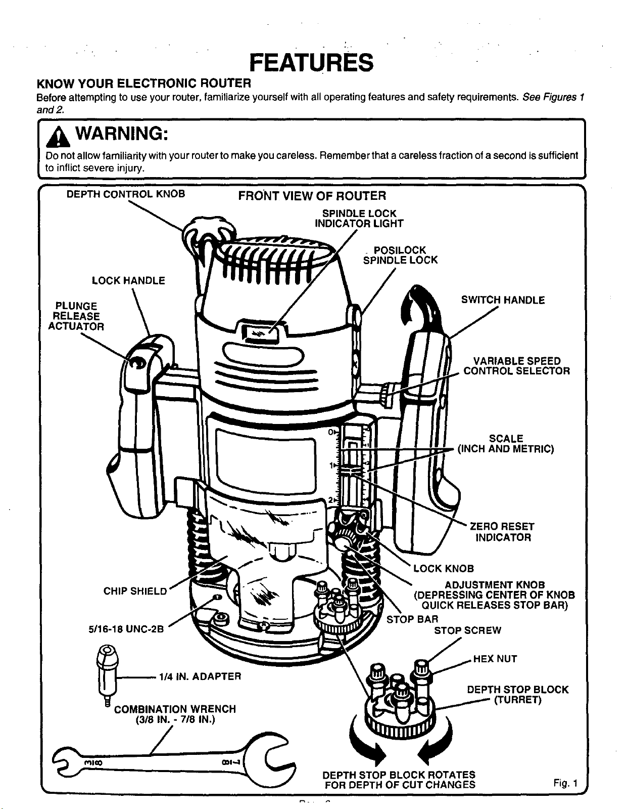
KNOW YOUR ELECTRONIC ROUTER
Beforeattemptingto useyourrouter,familiarizeyourselfwithalloperatingfeatures and safetyrequirements.See Figures1
and 2.
WARNING:
Do not allow familiarity with your router to make you careless. Remember that a careless fraction of a second issufficient
to inflict severe injury.
DEPTH CONTROLKNOB
LOCKHANDLE
PLUNGE
RELEASE
ACTUATOR
FRONT VIEW OF ROUTER
SPINDLE LOCK
INDICATOR LIGHT
. POSILOCK
SPINDLE LOCK
SWITCH HANDLE
VARIABLE SPEED
CONTROL SELECTOR
SCALE
(INCH AND METRIC)
_ZERO RESET
INDICATOR
KNOB
ADJUSTMENT KNOB
(DEPRESSING CENTER OF KNOB
QUICK RELEASES STOP BA_
5/16-18 UNC
(3/8 IN. - 7/8 IN,)
STOP BAR
STOPSCREW
DEPTH STOP BLOCK
/
DEPTH STOP BLOCK ROTATES
L
FOR DEPTH OF CUT CHANGES
Fig. I
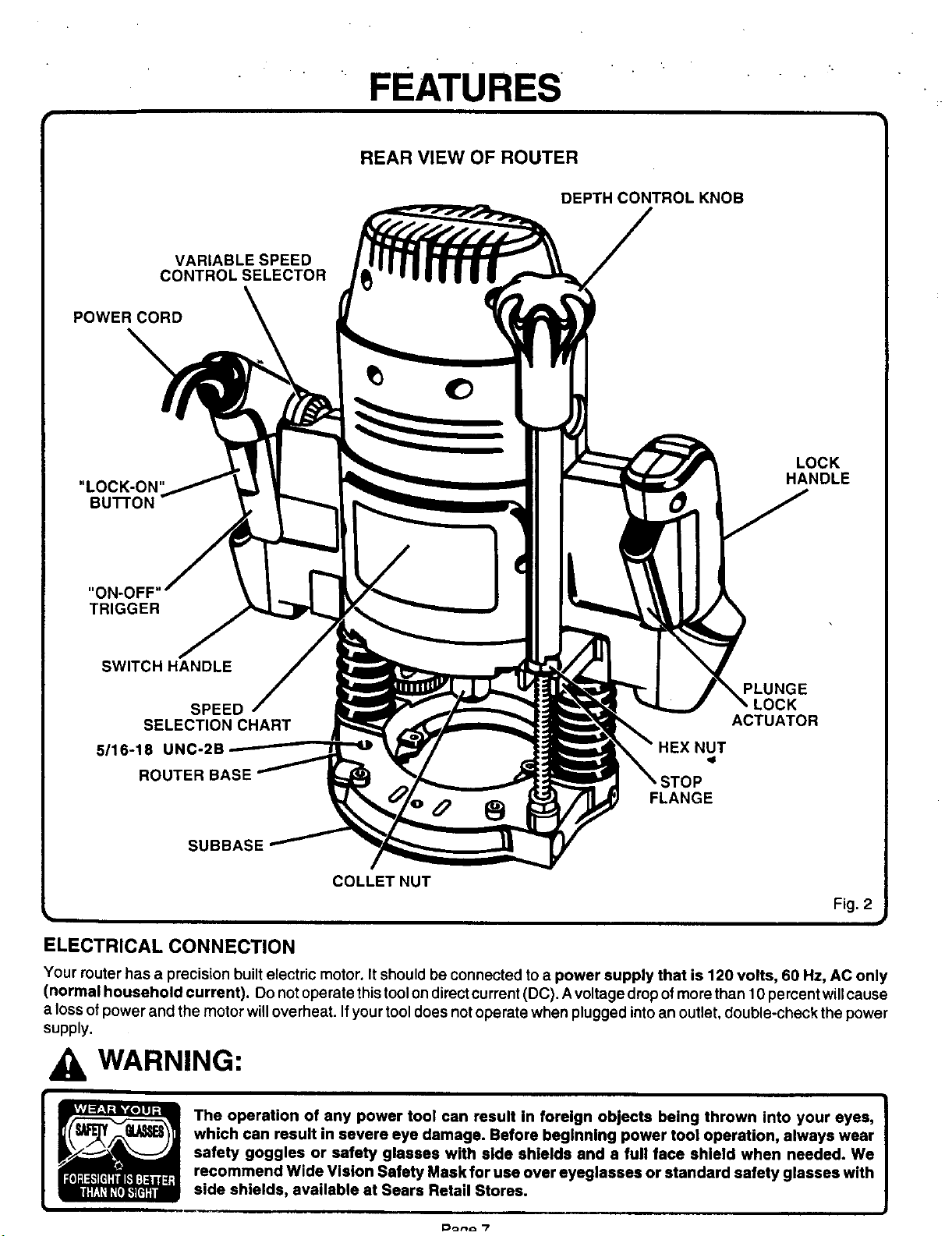
CONTROL SELECTOR
POWER CORD
"LOCK-ON"
BUTTON
FEATURES
REAR VIEW OF ROUTER
DEPTH CONTROL KNOB
VARIABLE SPEED
LOCK
HANDLE
"ON-OFF'
TRIGGER
SWITCH HANDLE
PLUNGE
SPEED
SELECTION CHART
5/16-18 UNC-2B
ROUTER BASE
FLANGE
SUBBASE
COLLETNUT
.OCK
ACTUATOR
Fig. 2
ELECTRICAL CONNECTION
Your muter has a precision built electric motor. It should be connected to a power supply that is 120 volts, 60 Hz, AC only
(normal household current). Do notoperate this toolon directcurrent(DC). A voltage drop ofmore than 10 percent willcause
a loss ofpower and the motor willoverheat. If your tooldoes notoperate when plugged intoan outlet, double-check the power
supply.
WARNING:
The operation of any power tool can result in foreign objects being thrown into your eyes,
which can result in severe eye damage. Before beginning power tool operation, always wear
safety goggles or safety glasses with side shields and a full face shield when needed. We
recommend Wide Vision Safety Mask for use over eyeglasses or standard safety glasses with
side shields, available at Sears Retail Stores.
10orv_ "7
ADJUSTMENTS '
WARNING:
Your router should never be connected to power supply
when you are assembling parts, making adjustments,
installing or removing cutters, or when not in use.
Disconnecting your router willprevent accidental starting
that could cause serious injury.
i
INSTALLING/REMOVING cu'n'ERS
See Figures3, 4, and 5.
I. UNPLUG YOUR ROUTER.
Failure to unplug your router could result in accidental
1- p
starting causing serious injury.
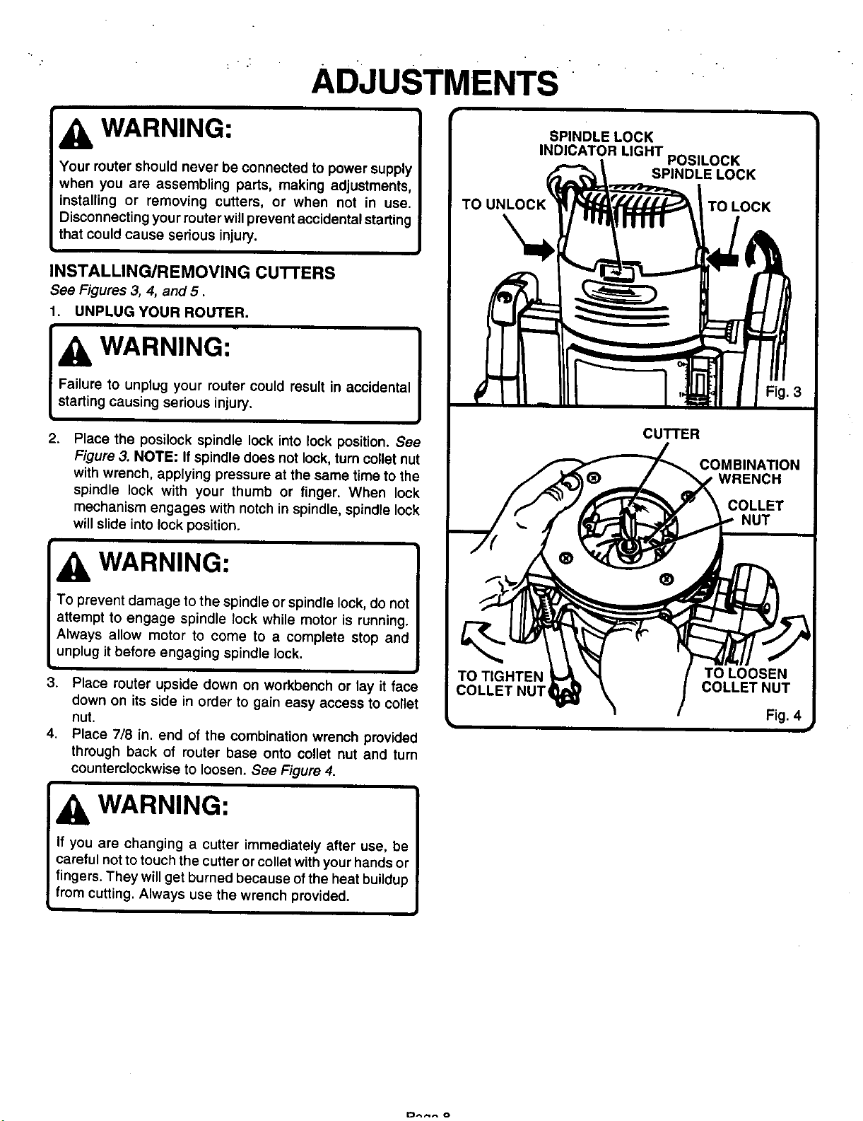
2.
Place the posilock spindle lock into lock position. See
Figure 3. NOTE: If spindle does not lock, turn collet nut
with wrench, applying pressure at the same time to the
spindle lock with your thumb or finger. When lock
mechanism engages with notch in spindle, spindle lock
will slide into lock position.
WARNING:
To prevent damage to the spindle or spindle lock, do not
attempt to engage spindle lock while motor is running.
Always allow motor to come to a complete stop and
unplug it before engaging spindle lock.
3. Place router upside down on workbench or lay it face
down on its side in order to gain easy access to conet
nut.
4. Place 7/8 in. end of the combination wrench provided
through back of router base onto collet nut and turn
counterclockwise to loosen. See Figure 4.
WARNING:
CUTTER
COMBINATION
WRENCH
COLLET
NUT
®
If you are changing a cutter immediately after use, be
careful not to touch the cutter or collet with your hands or
fingers. They will get burned because of the heat buildup
from cutting. Always use the wrench provided.
kl I
ADJUSTMENTS
INSTALLING/REMOVING CUTTERS
(Continued)
5. If installing cutter for the first time, it can be installed
once collet nut is loose. If changing cutters, cutter will
easily slip from collet after loosening collet nut.
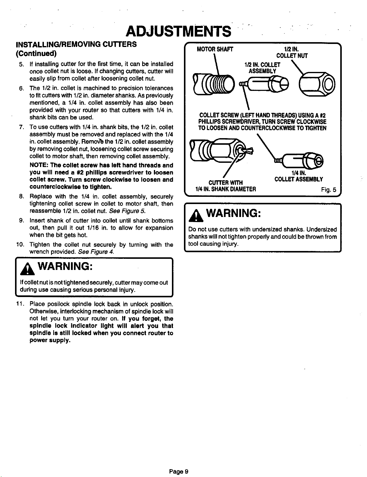
.
The 1/2 in. collet is machined to precision tolerances
to fitcutters with 1/2 in. diameter shanks. As previously
mentioned, a 1/4 in. collet assembly has also been
provided with your router so that cutters with 1/4 in.
shank bits can be used.
7.
To use cutters with 1/4 in. shank bits, the 1/2 in. collet
assembly must be removed and replaced with the 1/4
in,collet assembly. Remov_ethe 1/2 in.collet assembly
by removing collet nut, loosening collet screw securing
collet to motor shaft, then removing collet assembly.
NOTE: The collet screw has left hand threads and
you will need a #2 phillips screwdriver to loosen
collet screw. Turn screw clockwise to loosen and
counterclockwise to tighten.
S.
Replace with the 1/4 in. collet assembly, securely
tightening collet screw in collet to motor shaft, then
reassemble 1/2 in. collet nut. See Figure 5.
S.
Insert shank of cutter into collet until shank bottoms
out, then pull it out 1/16 in, to allow for expansion
when the bit gets hot.
10,
Tighten the collet nut securely by turning with the
wrench provided. See Figure 4.
MOTORSHAFT 1/2IN.
COLLETNUT
___1/2 IN.COLLET
COLLETSCREW(LEFTHANDTHREADS)USINGA#2
PHILLIPSSCREWDRIVER,TURNSCREWCLOCKWISE
TO LOOSENANDCOUNTERCLOCKWISETOTIGHTEN
CuI"rERWITH
1/4IN. SHANKDIAMETER Fig. 5
COLLETASSEMBLY
WARNING:
Do not use cutters with undersized shanks. Undersized
shanks will not tighten properly and could be thrown from
tool causing injury.
Ifcolletnut isnot tightened securely, cutter may come out
WARNING:
during usa causing serious personal injury.
11,
Place posilock spindle lock back in unlock position.
Otherwise, interlocking mechanism of spindle lock will
not let you turn your router on. If you forget, the
spindle lock Indicator light will alert you that
spindle Is still locked when you connect router to
power supply.
Page 9
 Loading...