

Craftsman 315275062 Owner’s Manual
OWNER'S
MANUAL
MODEL NO.
315.275062
CAUTION:
Read Rules for
CRRFTSMRN
Safe Operation
and All Instruc-
tions Carefully
Thank You for Buying
Craftsman Tools
6-95
Industrial Electronic
Plunge Router
Double Insulated
Warranty
Introduction
Unpacking
Features
Adjustments
Operation
Maintenance
Repair Parts
Designed exclusively lot and sold only by
SEARS, ROEBUCK AND (30, Ho[fman Estates, IL 60t 79
Prlnled in U,S,A

ItthisCraftsmanIndustrialElectronicPlungeRouterfailsdue toadefectinmatedal orworkmanshipwithinoneyear
fromthe dateofpurchase,Sears willrepairitfree ofcharge,Thiswarrantyappliesonlywhilethis productisinuse
in the UnitedStates. WARRANTY SERVICE IS AVAILABLE BY SIMPLY RETURNING THE TOOL TO THE
NEAREST SEARS STORE OR SERVICE CENTER THROUGHOUTTHE LINrrED STATES.
This warrantygives you specifto legal rights, and yDumay also haveother rightswhichvaryfromstateto state.
SITARS;ROEBUCKAND CO
DEPT. 817WA
L ........................................................
HOFFMAN ESTATES, IL 60179
iNTRODUCTiON
DOUBLE INSULATION is a conceptin safety, in electrlo
powertools,whicheliminates lhe need for the usualthree
wire groundedpower cord and grounded supply system.
Whereverthere is electric currantin the toolthere are two
completesets of insulationtoprotecttheuser, /kit exposed
metal partsare isolatedfrom internalmetal motor compo-
nentswith protectingInsulation,
IMPORTANT- Servicing of a tool withdouble Insulation
requiresexl_ome care end knowledgeof the systemand
shouldbe pedormedonly bya qualifiedservice technician,
For_ervfcewe suggestyoureturn the tool toyour nearest
SearsStoreforrepair, Always useoriginal factoryreplace.
mentpadswhenservicing,
RULES FOR SAFE OPERATION
READ ALL INSTRUCTIONS
1., KNOW YOUR POWFJRTOOL - Read owner'smanual carefully Learnitsapplicationsandlimitationsas weliasthe
specific potentialhazards related tothistool..
2, GUARD AGAINST ELECTRICAL,SHOCK BY PREVENTINGBODY CONTACT WITHGROUNDED SURFACES.
Forexample: Pipes,radiators,ranges,refrigeratorenclosures
3o KEEP GUARDS tN PLACE andinworkingorder,
4, KEEP WORK AREA CLEAN. Clutteredareasand benchesinviteaccidents,
5. /WOLDDANGEROUS ENVIRONMENT, Don'tusepowertoolindampor wetlocationsorexpose torain. Keepwork
areawaitiIL
6 KEEP CHILDREN AND VISITORS AWAY. Allvisitorsshouldwear safety glassesand bekeptasafe _istance
from work area,, Do not I_t visitorscontact too! orextensioncord
7 STORE IDLE TOOLS. When not in use tools shouldbe storedInadry,highorlocked-upplace- outof lhe reachof
children
8., DON'T FORCE TOOL. It wilt dothe job better and safer stthe ratefor whichitwas designed.
9. USERIGHT TOOL, Don't force smalltoot or attachment todo thejob of a heavy duty tool Don't usetoot for purpose
notintended - for example- Don't use acircularsaw forcuttingtreelimbs ortogs.
10. WEAR PROPER APPAREL. No loose clothingorjewelrytoget caughtinmovingparts_Rubbergrovesand non-
skidfootwearate recommended whenworkingoutdoors Also,wear protecSvehaircoveringto containlonghairand
keep Itfrom beingdrawn into airvents
t!, ALWAYS WEAR SAFETY GLASSES. Everyday eyeglasseshave only tmpact-reslstant lenses; they are NOT
safetyglasses,
12 PROTECT YOUR LUNGS, Wear a face or dustmask tfoperationis dusty
13. PROTECT YOUR HEARING. Wear hearingprotection dudngextendedperiodso!operation
!4.. DON'T ABUSE CORD. Never carrytoo_by cordor yank itto disconnect from_eceptac_e Keepcordfromheat, eli
andsharpedges.
Page2

RULES FOR SAFE OPERATION (Continued)
15. SECURE WORK. Usectampsor avise tohold work Bolh handsare needed tooperate thetool
16_ DON'T OVERREACH, Keep properfooting and balance at alltimes Donot useon a ladderorunstablesupport
17. MAINTAIN TOOLS WITH CARE Keep tools sharpatafltimes,and cleanfor bestand safestperformance.Follow
instruclionsfor lubricating and changingaccessodes_
18. DISCONNECT TOOLS, When notin use,before servicing, or whenchangingaltachments, blades,bits, cutters,
etc.,all toolsshould bedisconnectedf.rampowersupply.
19.. REMOVEADJUSTING KEYS AND WRENCHES, Formhabitofchec.kingtoseethatkeysandadjuslingwrenches
are removed fromtoolbefore turningiton..
20., AVOID ACCIDENTAL STARTING. Don'tcarry plugged-in tools with finger on switch Be sureswitchisoff when
pluggingin.,
21. MAKESURE YOUR EXTENSION CORD ISIN GOODCONDITION.When using an extension cord,be sureto use
one heavy enoughto carry thecurrentyour produclwittdraw.Anundersized cordwillcause a drop tnlinevoltage
resulting in lossof power and ove_eattng. A wlre gauge size (A.W.G) of at least 14 is recommendedfor an
extensioncord 25 feet or less In length.,A cord exceeding25 feet is not recommended,i1in doubt, use lh next
heaviergage. The smallerthe gage number, the heavierthe cord
22. OUTDOOR USE EXTENSION CORDS, When tootis usedoutdoors,useonlyextensioncords suitable foruse
outdoors,Outdoor approvedcordsare marked withthesuilixW,.A,forexample -SJTW-A or SJOW_A.
23. KEEPCUTTERS CLEAN AND SHARP. Shaq_cuttersminimizeslallingandkickback.
24. KEEP HANDS AWAY PROM CUTTING AREA. Keep handsaway from cutlers. Do not reach underneathwork
whilecutterisrotating. Donot attempt toremovematerialwhilecutteris rotating
25 NEVER USE INAN EXPLOSWE ATMOSPHERE. Normalsparkingel the motor couldignite fumes.,
26 INSPECT TOOL CORDS PERIOOICALLY and if damaged, have repaired atyour nearest SearsRepair Center
Stay constantlyaware el cordlocation.
27,. INSPECT EXTENSION CORDS PERIODICALLY andreplacetfdamaged.
28 KEEP HANDLES DRY, CLEAN, AND FREE FROM OIL AND GREASE, Always usea cleanclolhwhencleaning.
Neveruse brake fluids,gasoline, petroleum.based produclsoranystrong solventsto cleanyour tool,
29 STAYALERT. Watchwhat you aredoing anduse commonsense. Donor operate toolwhen you aretired, Donot
rush.
30 CHECK DAMAGED PARTS. Before ludheruseof thetool,aguardor otherpartthatisdamaged should be carefully
checkedtodetermine that ttwilloperate properlyandperformitsintendedfunction,.Check for alignment of moving
parts,blndtng of moving parts, breakage of parts,mounting,and anyotherconditionsthaimay affeclitsoperation., A
guardor other part that tsdamaged should be propedyrepaired or replaced by an authorizedservice center unless
Indicatedelsewherein thtsinstruction manual
31. DONOT USE TOOL IF SWITCH DOES NOT TURN IT ON AND OFF. Have defective switches replaced by an
authorizedservicecenter
32 Inspectfor and removeallnailsfrom tumber before muting..
33 DRUGS, ALCOHOL, MEDICATION. Do not operate tool while under the influence oFdrugs,alcohol, or any
medication
34. WHENSERVICING USEONLY IDENTICAL CRAFTSMAN REPLACEMENTPARTS.
35 POLARIZED PLUGS, To reduce the rfskofelectricshock,thistoolhasa polarizedplug(onebladeiswiderthanthe
other), This plugwtl!fit in a polarized outlet only one way. If theplugdoes notfit fully in theoutlet, reverse theplug.
if it stltldoes notfit,contacta qualifiedelectricianto install the proper outteL Do notchange lhe plugin anyway.
36. DONOT USE TOOL UNDER "BROWN-OUT" OR OTHERLOW VOLTAGE CONDITIONS, Also. do notuse with
any devicethat could cause lhe power supply voltagetochange,,
37. WHEN USING THIS ROUTER WITH A ROUTER TABLE, HELP PREVENT POSSIBLE SERIOUS INJURY BY
KEEPING THE Cbq'TERGUARDED AT ALL TIMES. Useonlyroutertables,wlih guards,thathave beendesigned
foruse on reuters thaiare of thistype, size, and weigh!
38 SAVETHESE INSTRUCTIONS. Review them frequentlyand usethemto Instructotherswho may use Ibis tool If
youloan someone thistool, loan them theseinstructionsalso.
Page3
UNPACKING
Yournew plungerouter comesfullyassembled. Afterremoving it fromthe box.inspecti_carefuflyto makesure that itIs
not damagedend that nopartsare missing, See Figure Io Thefollowingaocesso_esshould also be includedin the box"
1o CombinationWrench(3/8 In - 718In.,) 4., Roller(Contour)Guide
2, 1t4In. Adapter 5 GufdeBushing
3. EdgeGuide
FEATURES
Your electronicrouter is a versatile woodworkingtoo! whichwitl give you years of trouble-free performance. It is
engineeredwiththeprofessionaltn mind, butits ease of operationsnowsthe amateurtoproduceworkwhichis beautiful
and precise,,
3.5 HORSEPOWER MOTOR
Your routar has a powerful3°5 horsepowermotor wilh
sufficientpower to handle thetoughestroutingjobs. The
motoralsohas externallyaccessiblebnJshesfor ease of
servicing,,
SOFT START
The softstart featurebuildsmotor RPM graduallyto minf_
mize sled.up torque Pressing or releasingthe "on-aft"
tdggert_l{ rumyour reufer on or off_
DEPTH CONTROL KNOB
A large depth controlknob makes precise depth of cul
changespossible, it also is very hefpfutwhen making
depth o! cut changes with your router mountedupside
downon_t routertable.
DEPTH STOP SYSTEM
The depthstop block!ocaled on the base of your router
provides three adjustable stops and throe fixedstopsfor
quick depth of cut changes, A depth adiustment scale
makes quick adjustmentsto depth of cut changes pos-
sible. The spring loadedadjustmentknob quickreleases
stop bar by depressingcenterof knob,
1/4 IN. AND !/2 IN. SHANK CAPACITY
Your router has a 1t2 in, ctlameter coital that accepts
cutterswith !/2 in. shanks. An adapterhasbeenprovided
Sothat cutterswith1t4 ln.shank bitscan alsobe used.
CHIP SHIELD
A clearplasticsee-through chip shield has beenprovided
onthe baseof yourrouter for protectionagainstflyingdual
and chips,, It is designedto fit the front openingof the
routerbase.,
POStLOCK SPINDLE LOCK
A positockaplndielock securesthe spindleso that only
one wrench is needed to loosen cotternul and change
cutters. A spindle lock indicator light alerts you that
spines is lookedif you connectrouterto power supply
beforeunlockingspindle, NOTE: Yourrouterwillnotrun if
spindleislocked.,
"LOCK-ON" FEATURE"
Your router Is equipped with a 'lock-on" feature that is
convenientwhencontinousoperation forextendedperiods
of time isrequired
LARGE HANDLES
Your router haslarge oversizedhandlesforeasyhandling
and maintaining propercontrolwhen routing The left
handle allows you to set cutterdepthof cutwhenmaking
plungecuts,whitethe dghthandleprovideseasy access
tothe "on-oil" tdgger, "lock.on'button, and vadsblespeed
controlselector_ Thehandleshave also been desEgnedso
thatthey are comfortableand easytograsp whenoperat-
ing in differentpositionsor at different angles,,
VARIABLE SPEED SWITCH WITH ELECTRONIC
SPEED CONTROL (Feedback Switch)
Yourrouterhas advancedelectronic features,designedto
assist you in getting the maximum use from your router_
By making proper speed selections,your muter can be
adjusted to specticroutingneeds. Th{eeliminates much of
the guesswork previouslyneeded toperforma given job,
BOththeexpenenced and inexperienced router usersben-
slit, obtainingprofessionaltfkerosuIIs with fewer job er-
rors,,
The vadablespeedcontrolallows the routerspeed to be
adjustedfrom10,060 to 25,000 rpm The variablespeed
controlselelctor is convenientlylocated inside the right
handleneartheoperator'sthumborhand°
The electronicfeature ofyourrouter introducesthe tlexibil.
ityo! adlustlng the motor_peedto requiredjobconditlo_so
An electronic speed controlmodulesenses the load alP
plied to the motor, and increases or decreases motor
voltageto compensateforand maintaindesiredRPM
Speed can be set accordfngto the approximatecutter
diameter you will be using and to the hardnessof the
matedaJbeingcuL The best cutsaremade whenthecutter
isfedthroughmatedalat the prope_"rateof feed.
ROUTER ACCESSORIES
Your router comes equippedwith several accessories,
The edgeguide keepsthe cutterparallelwithan edge of
the workplacewhen culling groovesand rabbets. The
ro|ler (contour)guideallowsthe router to be usedto trim
laminatesandmakeouts parallelwithan irregularlyshaped
edge. The template guide bushingenablesthe router to
followa template for makingduptfceteshapes.
Page 4
FEATURES
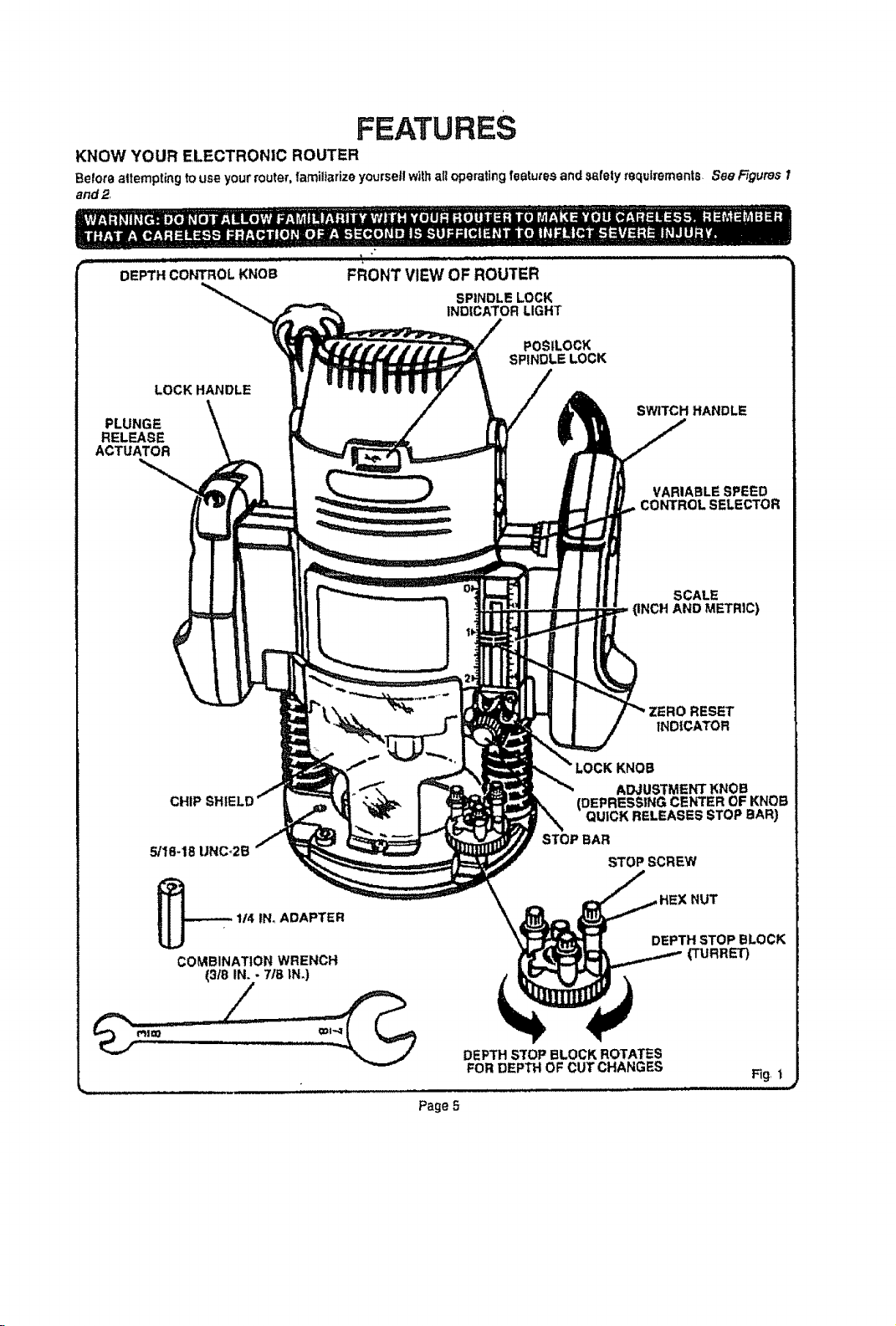
KNOW YOUR ELECTRONIC ROUTER
Belote altempting to use your router, familiarize yourse|l withall operating features and safely requirements. See Figures 1
and 2.
DE 'cobOL KNOB"
LOCK HANDLE
PLUNGE
RELEASE
ACTUATOR
FRONT VIEW OF ROUTER
SPINDLE LOCK
INDICATOR LIGHT
POSILOCK
SPINDLE LOCK
SWITCH HANDLE
VARIABLE SPEED
CONTROL SELECTOR
SCALE
(INCH AND METRIC)
ZERO RESET
INDICATOR
CHIP
5/18-18 UNC_2B
114 tN_ADAPTER
COMBINATION WRENCH
(3t8 IN. - 7IB IN.)
STOP BAR
DEPTH S'fOP BLOCK ROTATES
FOR DEPTH OF CUT CHANGES
Page 5
KNOB
ADJUSTMENT KNOB
(DEPRESSING CENTER OF KNOB
QUICK RELEASES STOP BAR)
NUT
DEPTH STOP BLOCK
(TURRET)
Fig. 1
VARIABLE SPEED
CONTROL SELECTOR
POWER CORD k
"LOCK*ON
BUTTON
=ON-OFF
TRIGGER
FEATURES
REAR VIEW OF ROUTER
DEPTH CONTROL KNOB
LOCK
HANDLE
SWITCH HANDLE
SPEED
SELECTION CHART
5/!6-18 UNC-2E
ROUTER BASE
SUBBASE
HEX NUT
FLANGE
K
ACTUATOR
COLL.ETNUT
• . ....L .... , UJ,,.,tvu,u_II UII'L I,. .... I..I -- =
Fig 2
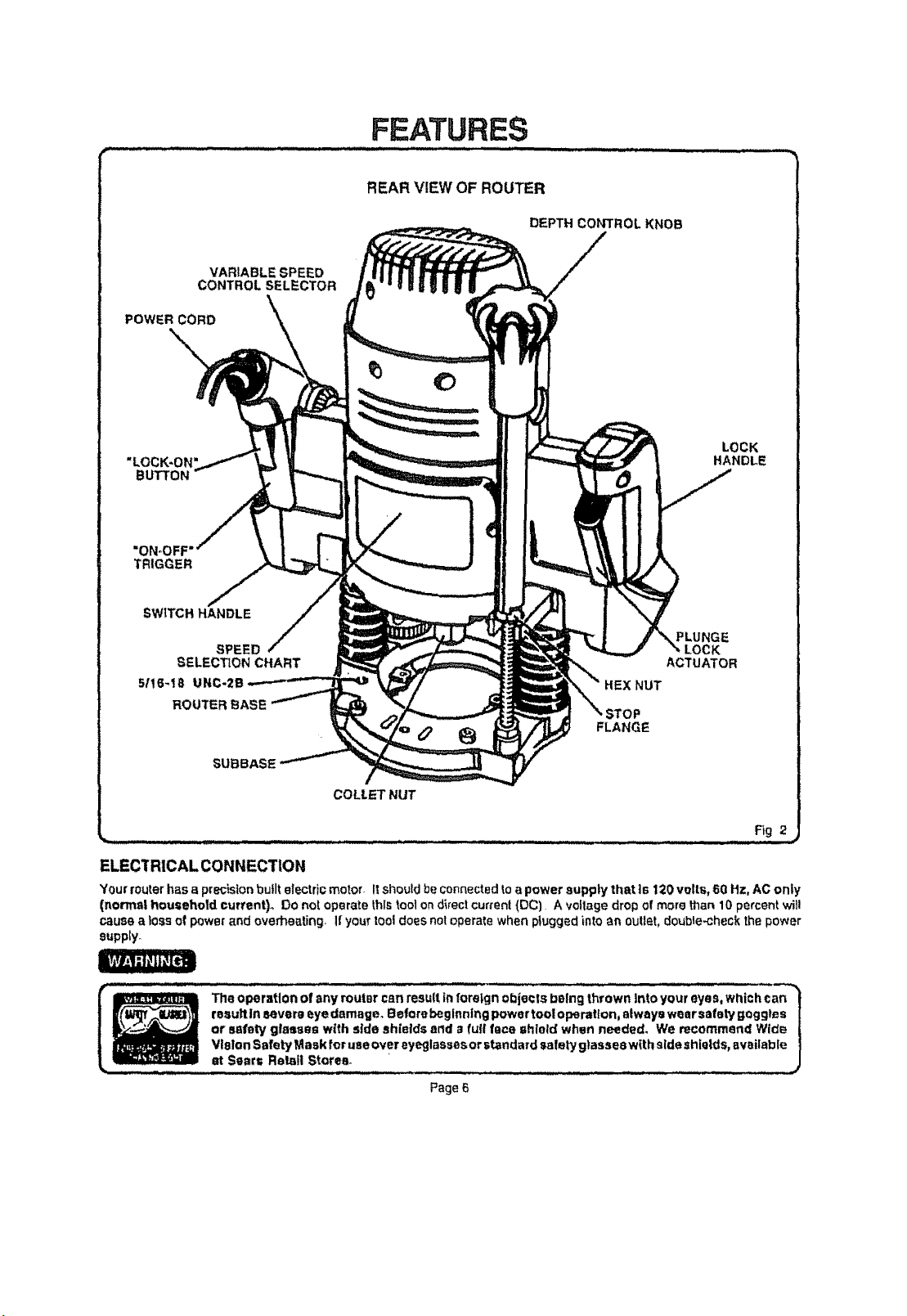
ELECTRICAL CONNECTION
Your routerhasa precistonbufltelectric motor. Itshoutdbecennected toapowersuppiy thatts 120voltr,,60 Hz,AC only
(normal househotdcurrent). Donotoperatethistoo] ondirectcurten!(PC) A vo!lagedropof more than10percent wil!
causea lossofp_we_and overheating, ifyour tooldoes notoperatewhen plugged into an oulf_,t,double,checkthe power
supply_
i | _ Z _11 The operation of any route, csn result |n fore|gn objects being thrown Into your ayes, which car=
i i _U_ _e_u_t_nsever_eyedamage_Be__rebeg_nnIng_p_wert____p_ra___n_a_way_wearsafetygogg_es|
+ --_ or safety glasses with side shields and a full lace shield when needed, We recommend Wid_ |
,.Sea,...,e_,Sto_;,...+ ........_ ...........................+............... j
Page 6
ADJUSTMENTS
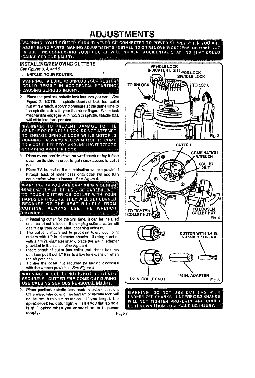
INSTALLING/REMOVING CUTTERS
See Figures3, 4, and 5 _
I. UNPLUG YOUR ROUTER,
2+
Placethe posilock spfndtelock Into lock position, See
Figure3. NOTE: if spindledoes not lock, turncotlet
nutwithwrench,applylng pressureat the sametime to
Ihe spindlelock withyourthumbor finger. When lock
mechanism engageswithnotch in spindle,spindlelock
wiltslide Intolockposition.
3 Place touter upsidedownon workbenchor lay it face
down on its sidein orderto gain easyaccess to collet
nLff_
4, Place 718in, end of the combinationwrenchprovided
throughback of routerbase onto coital nut and turn
counte_ockwisa to loosen. See Figure4,
TO
SPINDLE LOCK
INDICATOR LIGHT POSILOCK
SPINDLE LOCK
TO LOCK
CUTTER
COMBIHATIOI, t
;t3
WRENCH
COLLET
NUT
5 If installing cutterfor the firs! time.it can be installed
once colfetnut is loose+ Ifchangingcutters,cutterwilt
easily slipfromcollet at_erlooseningcolietnut
6 The collar is machined to precisiontolerancesto tit
cutterswith I/2. in,,diametershanks If usinga cutter
with a !14 in, diametershank,place the 1/4 in adapter
providedin the colleL See Figure.5
7 Insert shankof cutter into coltet unlit shank bottoms
out.then puii fl out 11t6in Ioallow forexpansionwhen
the bit getshot.
8 Tighten Ihe coital nut securely by turningclockwise
with thewrenchprovided, See Figure4.
9,
Place posilock spindle lock back in unlock position.
Otherwise, interlocking mechanism of sptndle lock will
nol let you turn your router on. If you forget, the
spindle lock Indicator light wilt alert you thai spindle
is still locked when you connect router to power
supply.
Page 7
TO TIGHTEN
COLLET NUT_
CUTTERWITH 114IN.
SHANKDIAMETER
114IN. ADAPTER
1/2 IN,COLLET NUT Fig.,5_
ADJUSTMENTS
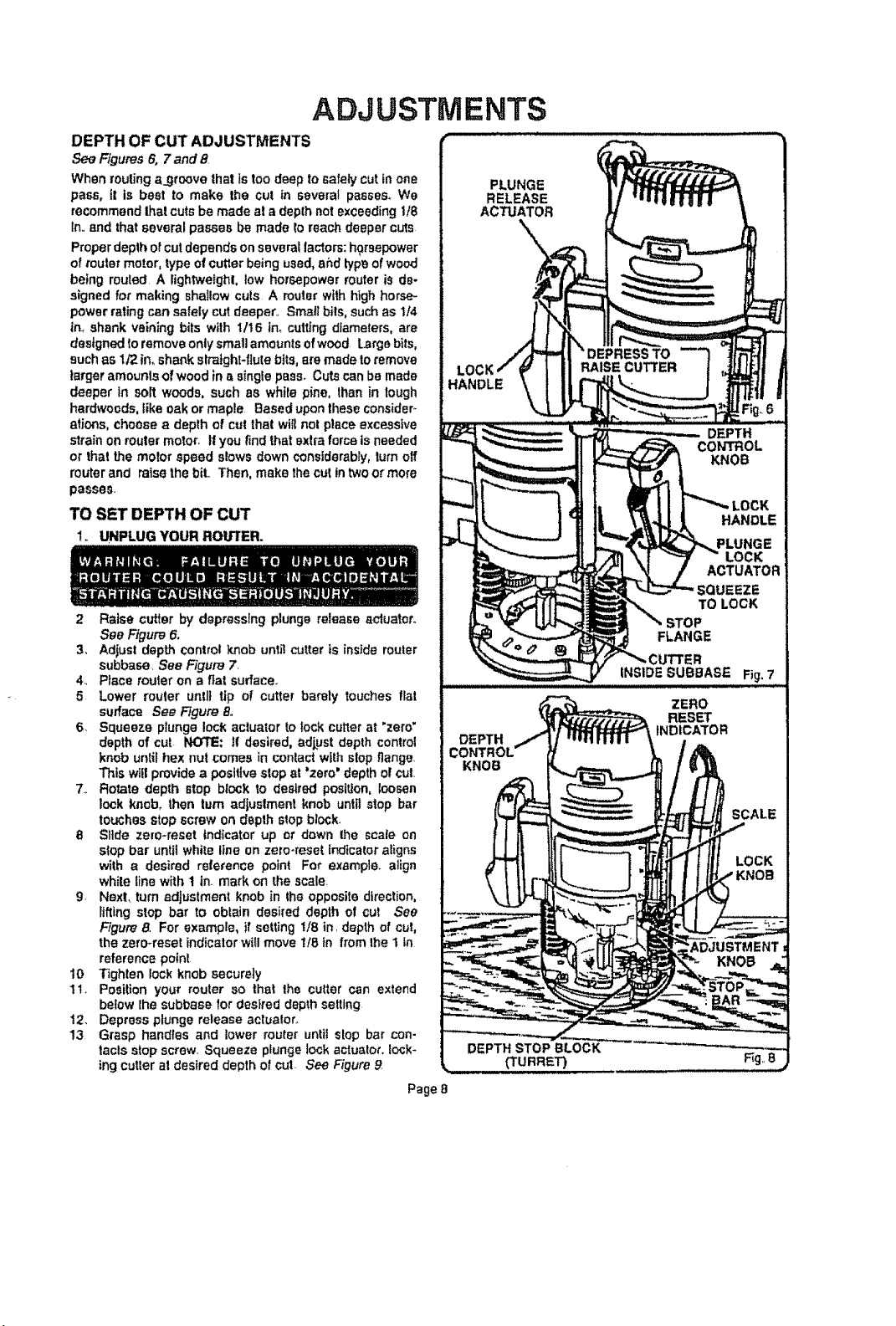
DEPTH OF CUT ADJUSTMENTS
See Figures6, 7 and 8
When routing a_groovethat istoodeepto safely cutin one
pass, it is beet to make the cut in several passes.We
recommendthatcute be made ala depthnot exceedingU8
In,.and thatseveralpassesbe made rereachdeepercuts
Properdepthofcutdependson severallactors: horsepower
ofrouter motor,typeofcutterbeingused,ahd typeofwood
being routed.A lightweight, low horsepowermuter is de-
signedfor makingshaIIow culs A muterwithhigh horse-
powerrating cansafelycut deeper.. Smallbils, suchas It4
innshankveiningbits with 1/16 inocuttingdiameters,are
designedtoremoveontysmallamountsofwood large bits,
suchas 1/2in, shankslraight-fiutebits,ammadeto remove
largeramountsof woodin asinglepass. Cutscanbe made
deeper in soft woods, such as white pine, lhan in lough
hardwoods,like oak ormaple Based upon theseconsider-
aticms,choose a depth of cut thatwiltnot place excessive
strainon routermotor. If youfindthatextraforceisneeded
or that the reeler speedslowsdownconsiderably,turnoff
muterand raisethe bit. Then,make thecutintweet more
passes.
TO SET DEPTH OF CUT
1. UNPLUG YOUR ROU']rER.
2 Raise cutter by depressing plunge release aduatoro
See Figure 6.
3, Adjust depth control knob unti! c'_tter is inside router
subbese. See Figure 7
4. Place router on a fiat surface..
5 Lower router unlit tip of cutter barely touches flat
surface See Figure 8,
6 Squeeze plunge lock actuator to lock cutter at 'zero'
depth of cut NOTE: tf desired, adjpst depth control
knob until hex nul comes in contact with slop flange.
This wtl!provide a positive stop at "zero" depth of cut.
7., Rotate depth stop block to desired position, loosen
lock knob, then turn adjustment knob until stop bar
touches stop screw on depth stop block,
8 Slide ze[o-reset indicator up or down the scale on
stop bar until white line on zero-meet indicator aligns
with a desired reference point For example, align
while line with 1 in. mark on the scale.
g, Next, turn adjustment knob in lhe opposite direction,
lifting stop bar to obtain desired depth of cul See
Figure 8, For example, if setting 1t8 in. depth of cut,
the zero-reset indicator will move 1t8 in from the 1 in
reference point
10 Tighten lock knob securely
11. Position your router so that the cutter can extend
below lhe subbase for desired depth setting
12. Depress plunge release actuaIor.
13 Grasp handles and lower muter until slop bar con-
tacls stop screw. Squeeze plunge lock actuato_. Io_k-
tng cutter at desired depth of cut. See Figure 9
Page 8
 Loading...