

Craftsman 315275061 Owner’s Manual

Sz:_AJ_
OWNER'S
MANUAL
MODELNO.
315.275061
CAUTION:
Read Rules for
Safe Operation
and All Instruc-
tions Carefully
CRRFTSMRN°
Industrial Electronic
Plunge Router
Double Insulated
Warranty
Introduction
Unpacking
Features
Adjustments
Thank You for Buying
Craftsman Tools
972000-092 Printed In U.S.A.
3-95
Operation
Maintenance
, Repair Parts
Sold only by
SEARS, ROEBUCK AND CO., Hoffman Estates, IL 60179
®

FULL ONE YEAR WARRANTY ON CRAFTSMAN INDUSTRIAL ELECTRONIC PLUNGE ROUTER
If this Craftsman Industrial Electronic Plunge Router fails due to a defect in material or workmanship within one year
from the date of purchase, Sears will repair it free of charge. This warranty applies only while this product is in use
in the United States, WARRANTY SERVICE IS AVAILABLE BY SIMPLY RETURNING THE TOOL TO THE
NEAREST SEARS STORE OR SERVICE CENTER THROUGHOUT THE UNITED STATES,
This warranty gives you specific legal rights, and you may also have other rights which vary from state to state.
SEARS, ROEBUCK AND CO.
DEPT. 817 WA
HQFFMAN ESTATES, IL 60179
INTRODUCTION
DOUBLE INSULATION is a concept in safety, in electric IMPORTANT - Servicing of a tool with double insulation
power tools, which eliminates the need for the usual three requires extreme care and knowledge of the system and
wire grounded power cord and grounded supply system, should be performed only by a qualified service technician.
Wherever there is electric current in the tool there are two For service we suggest you return the tool to your nearest
complete sets of insulation to protect the user. All exposed Sears Store for repair. Always use original factory replace-
metal parts are isolated from internal metal motor compo- ment parts when servicing.
nents with pretecting insulation.
RULES FOR SAFE OPERATION
READ ALL INSTRUCTIONS
1. KNOW YOUR POWER TOOL - Read owner's manual carefully. Learn its applications and limitations as well as the
specific potential hazards related to this tool.
2. GUARD AGAINST ELECTRICAL SHOCK BY PREVENTING BODY CONTACT WITH GROUNDED SURFACES.
For example: P!pes, radiators, ranges, refrigerator enclosures.
3. KEEP GUARDS IN PLACE and in working order.
4. KEEP WORK AREA CLEAN. Cluttered areas and benches invite accidents.
5. AVOID DANGEROUS ENVIRONMENT. Don't use power tool indamp or wet locations or expose to rain. Keep work
area well lit.
6. KEEP CHILDREN AND VISITORS AWAY. All visitors should wear safety glasses and be kept a safe distance
from work area. Do not let visitors contact tool or extension cord.
7. STOREIDLETOOLS. When not in use tools shouid be stored in a dry, high or locked-up place - out of the reach of
children.
8. DON'T FORCE TOOL. Itwilldothejobbetterandsaferattherateforwhichitwasdesigned.
9. USE RIGHT TOOL. Don't force small tool or attachment to do the job of a heavy duty tool. Don't use tool forpurpose
not intended - for example - Don't use a circular saw for cutting tree limbs or logs.
10. WEAR PROPER APPAREL. No loose clothing or jewelry to get caught in moving parts. Rubber gloves and non-
skid footwear are recommended when working outdoors. Also, wear protective hair covering to contain longhair and
keep it from being drawn into air vents.
lt. ALWAYS WEAR SAFETY GLASSES. Everyday eyeglasses have only impact-resistant lenses; they are NOT
safety glasses.
12. PROTECT YOUR LUNGS. Wear a face or dust mask if operation is dusty.
13. PROTECT YOUR HEARING. Wear hearing protection during extended periods of operation.
14, DON'T ABUSE CORD. Never carry tool by cord or yank it to disconnect from receptacle. Keep cord from heat, oil
and sharp edges,
Page 2

RULES FOR SAFE OPERATION (Continued)
15. SECURE WORK. Use clamps or a vise to hold work. Both hands are needed to operate the tool,
16. DON'T OVERREACH. Keep properfooting and balance at all times, Do not use ona ladder or unstable support
17. MAINTAIN TOOLS WITH CARE. Keep tools sharp at all times, and clean for best and safest performance. Follow
instructionsfor lubricating and changing accessories.
i! 18. DISCONNECT TOOLS. When not in use, before servicing, or when changing attachments, blades, bits, cutters,
etc,, all tools should be disconnected from power supply.
19. REMOVE ADJUSTING KEYS AND WRENCHES. Form habit of checkingtosee thatkeys and adjusting wrenches
are removed from tool before turning it on.
20. AVOID ACCIDENTAL STARTING. Don't carry plugged-in tools with finger on switch, Be sure switch is off when
plugging in.
21. MAKE SURE YOUR EXTENSION CORD 13IN GOOD CONDITION. When using an extension cord, be sure to use
one heavy enough to carry the current your product will draw. An undersized cord will cause a drop in line voltage
resulting in loss of power and overheating. A wire gauge size (A.W,G.) of at least 14 is recommended for an
extension cord 25 feet or less in length, A cord exceeding 25 feet is not recommended. If in doubt, use th next
heavier gage. The smaller the gage number, the heavier the cord.
22. OUTDOOR USE EXTENSION CORDS. When tool is used outdoors, use only extension cords suitable for use
outdoors. Outdoor approved cords are marked with the suffix W-A, for example - SJTW-A or SJOW-A.
23, KEEP CUTTERS CLEAN AND SHARP. Sharp cutters minimize stalling and kickback,
24. KEEP HANDS AWAY FROM CUTTING AREA. Keep hands away from cutters. Do not reach underneath work
while cutter is rotating, Do not attempt to remove material while cutter is rotating.
25, NEVER USE IN AN EXPLOSIVE ATMOSPHERE. Normal sparking of the motor could ignite fumes.
26. INSPECT TOOL CORDS PERIODICALLY and if damaged, have repaired at your nearest Sears Repair Center.
Stay constantly aware of cord location,
27. INSPECT EXTENSION CORDS PERIODICALLY and replace ifdamaged,
28, KEEP HANDLES DRY, CLEAN, AND FREE FROM OIL AND GREASE. Always use a clean cloth when cleaning,
Never use brake fluids, gasoline, petroleum-based products or any strong solvents to clean your tool.
29. STAY ALERT. Watch what you are doing and use common sense. Do not operate tool when you are tired. Do not
rush.
30. CHECK DAMAGED PARTS. Before further use of the tool, a guard or other part that is damaged should be carefully
checked to determine that it will operate properly and perform its intended function. Check for alignment of moving
parts, binding of moving parts, breakage of parts, mounting, and any other conditions that may affect its operation. A
guard or other part that is damaged should be properly repaired or replaced by an authorized service center unless
indicated elsewhere in this instruction manual.
31. DO NOT USE TOOL IF SWITCH DOES NOT TURN IT ON AND OFF. Have defective switches replaced by an
authorized service center.
32. Inspect for and remove all nails from lumber before routing.
DRUGS, ALCOHOL, MEDICATION. Do not operate tool while under the influence of drugs, alcohol, or any
33.
medication.
34.
When servicing use only identicat Craftsman replacement parts.
35. POLARIZED PLUGS. To reduce the risk of electric shock, this tool has a polarized plug (one blade is wider than the
other). This plug will fit in a polarized outlet only one way. If the plug does not fit fully inthe outlet, reverse the plug.
If it still does not fit, contact a qualified electrician to install the proper outlet. Do not change the plug inany way.
36. DO NOT USE TOOL UNDER "BROWN-OUT" OR OTHER LOW VOLTAGE CONDITIONS. Also, do not use with
any device that could cause the power supply voltage to change.
37. WHEN USING THIS ROUTER WITH A ROUTER TABLE, HELP PREVENT POSSIBLE SERIOUS INJURY BY
KEEPING THE CUTTER GUARDED AT ALL TIMES. Use only router tables, with guards, that have been designed
for use on reuters that are of this type, size, and weight.
38, SAVE THESE INSTRUCTIONS. Review them frequently and use them to instruct others who may use this tool. If
you loan someone this tool, loan them these instructions also.
Page 3
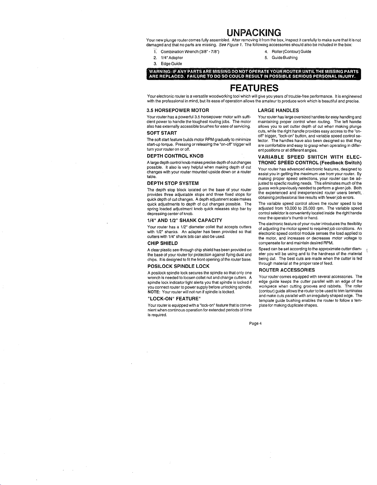
UNPACKING
Your new plunge router comes fully assembled. After removing it from the box, inspect itcarefully to make sure that it is not
damaged and that no parts are missing. See Figure 1. The following accessories should also be included in the box:
1_ Combination Wrench (3/8"- 7/8") 4, Roller(Contour) Guide
2. 1/4"Adapter 5. Guide Bushing
3. Edge Guide
FEATURES
Your electronic router is a versatile woodworking toot which will give you years of trouble-free performance. It isengineered
with the professional in mind, but its ease of operation allows the amateur to produce work which is beautiful and precise.
3.5 HORSEPOWER MOTOR
Your router has a powerful 3.5 horsepower motor with suffi-
cient power to handle the toughest routing jobs. The motor
also has externally accessible brushes for ease of servicing.
SOFT START
The soft start feature builds motor RPM gradually tominimize
start-up torque. Pressing or releasing the "on-oft" trigger will
turn your router on or off.
DEPTH CONTROL KNOB
A largedepth control knob makes precise depth of cut changes
possible. It also is very helpful when making depth of cut
changes with your router mounted upside down on a router
table.
DEPTH STOP SYSTEM
The depth stop block located on the base of your router
provides three adjustable stops and three fixed stops for
quick depth of cut changes. A depth adjustment scale makes
quick adjustments to depth of cut changes possible. The
spring loaded adjustment knob quick releases stop bar by
depressing center of knob.
1/4" AND 1/2" SHANK CAPACITY
Your router has a 1/2" diameter collet that accepts cutters
with 1/2" shanks. An adapter has been provided so that
cutters with 1/4" shank bits can also be used,
CHIP SHIELD
A clear plastic see-through chip shield has been provided on
the base of your router for protection against flying dust and
chips. It is designed to fit the front opening of the router base,
POSiLOCK SPINDLE LOCK
A posilock spindle lock secures the spindle so that only one
wrench is needed to loosen collet nut and change cutters. A
spindle lock indicator light alerts you that spindle is locked if
you connect router to power supply before unlocking spindle.
NOTE: Your router wilt not run if spindle is locked.
"LOCK-ON" FEATURE"
Your router is equipped with a "lock-on" feature that is conve-
nient when continous operation for extended periods of time
is required.
LARGE HANDLES
Your router has large oversized handles for easy handling and
maintaining proper control when routing. The left handle
allows you to set cutter depth of cut when making plunge
cuts, while the right handle provides easy access to the "on-
off" trigger, "lock-on" button, and variable speed control se-
lector. The handles have also been designed so that they
are comfortable and easy to grasp when operating in differ-
ent positions or at different angles.
VARIABLE SPEED SWITCH WITH ELEC-
TRONIC SPEED CONTROL (Feedback Switch)
Your router has advanced electronic features, designed to
assist you ingetting the maximum use from your router. By
making proper speed selections, your router+can be ad-
justed to specfic routing needs. This eliminates much of the
guess work previously needed to perform a given job. Both
the experienced and inexperienced router users benefit,
obtaining professional like results with fewer job errors.
The variable speed control allows the router speed to be
adjusted from 10,000 to 25,000 rpm+ The variable speed
control selelctor is conveniently located inside the righthandle
near the operator's thumb or hand.
The electronic feature of your router introduces the flexibility
of adjusting the motor speed to required job conditions. An
electronic speed control module senses the load applied to
the motor, and increases or decreases motor voltage to
compensate for and maintain desired RPM.
Speed can be set according to the approximate cutter diam-
eter you will be using and to the hardness of the material
being cut. The best cuts are made when the cutter is fed
through material at the proper rate of feed.
ROUTER ACCESSORIES
Your router comes equipped with several accessories. The
edge guide keeps the cutter parallel with an eclge of the
workpiece when cutting grooves and rabbets. The roller
(contour) guide allows the router to be used totrim laminates
and make cuts parallel with an irregularly shaped edge. The
template guide bushing enables the router to follow a tem-
plate for making duplicate shapes.
Page 4
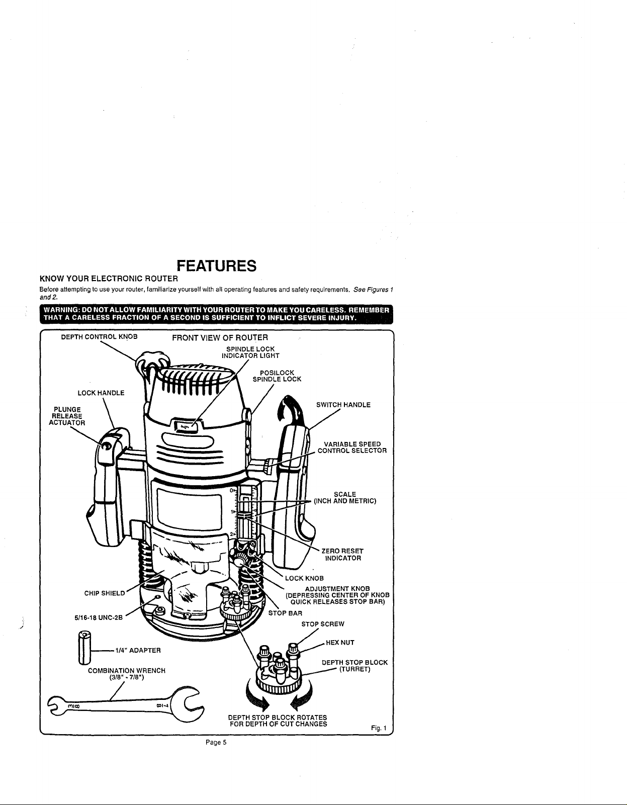
FEATURES
KNOW YOUR ELECTRONIC ROUTER
Before attempting to use your router, familiarize yourself with all operating features and safety requirements. See Figures 1
and2.
DEPTH CONTROL KNOB
LOCK HANDLE
PLUNGE
RELEASE
ACTUATOR
_16-18
FRONT VIEW OF ROUTER
SPINDLE LOCK
INDICATOR LIGHT
SPINDLE LOCK
POSILOCK
SWITCH HANDLE
VARIABLE SPEED
CONTROLSELECTOR
(INCH AND METRIC)
INDICATOR
KNOB
ADJUSTMENT KNOB
(DEPRESSING CENTER OF KNOB
QUICK RELEASES STOP BAR)
STOP BAR
STOP SCREW
SCALE
ADAPTER
COMBINATION WRENCH
(3/8" - 7/8")
DEPTH STOP BLOCK ROTATES
FOR DEPTH OF CUT CHANGES
Page 5
]EX NUT
DEPTH STOP BLOCK
Fig, 1
POWER CORD
\
"LOCK-ON"
BUTTON
"ON-(3
TRIGGER
SWITCH HANDLE
SELECTION CHART
5/16-18 UNC-2B
ROUTER
VARIABLE SPEED
CONTROL SELECTOR
SPEED
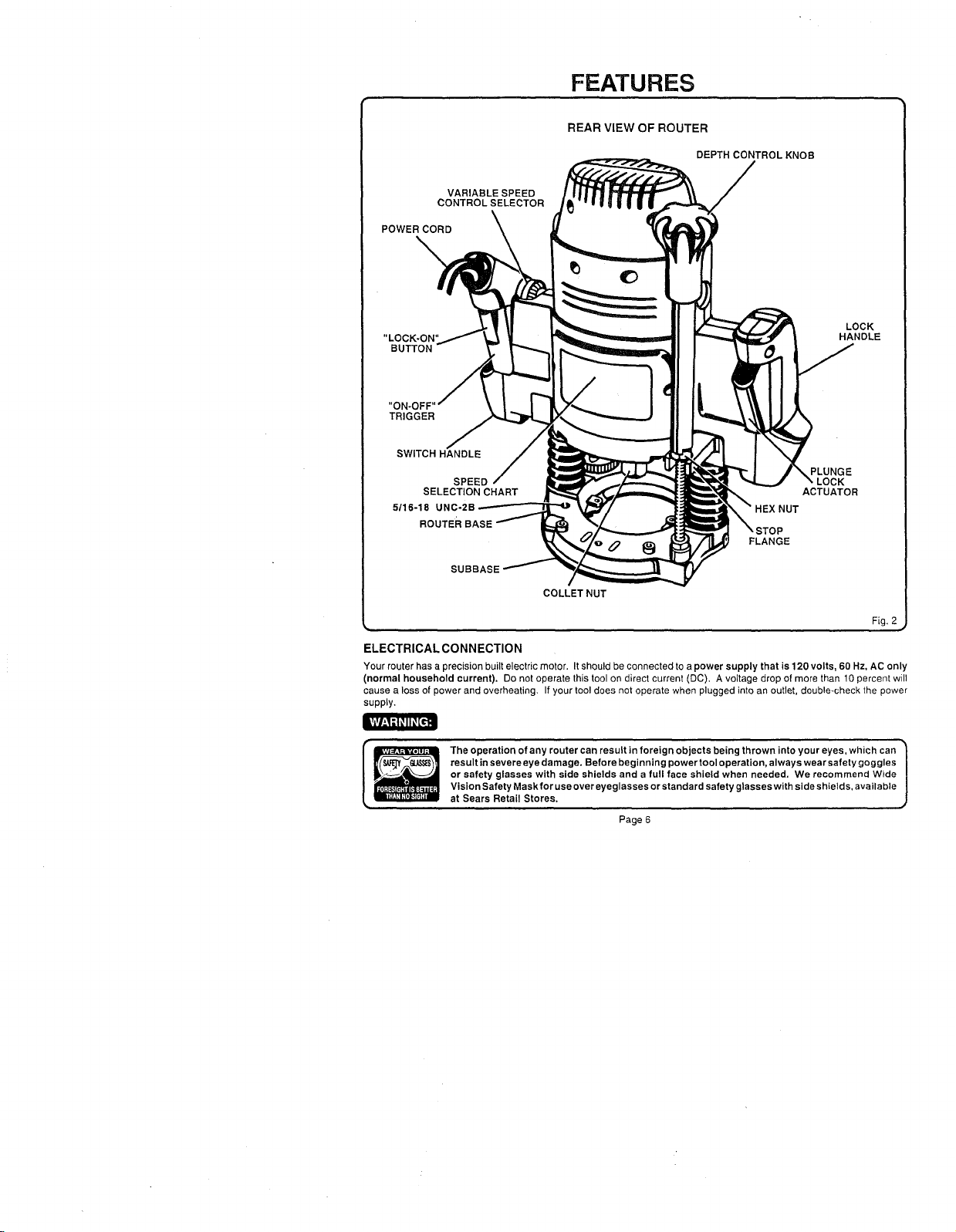
FEATURES
REAR VIEW OF ROUTER
DEPTH CONTROL KNOB
HEX NUT
FLANGE
PLUNGE
ACTUATOR
LOCK
HANDLE
SUBBASE
COLLET NUT
Fig. 2
ELECTRICAL CONNECTION
Your router has a precision built electric motor. It should be connected to a power supply that is 120 volts, 60 Hz, AC only
(normal household current). Do not operate this tool on direct current (DC). A voltage drop of more than 10 percent will
cause a loss of power and overheating. If your tool does not operate when plugged into an outlet, double-check the power
supply.
The operation of any router can result in foreign objects being thrown into your eyes, which can
result in severe eye damage. Before beginning power tool operation, always wear safety goggles
or safety glasses with side shields and a full face shield when needed. We recommend Wide
Vision Safety Maskfor use over eyeglasses or standard safety glasses with side shields, available
at Sears Retail Stores.
Page 6
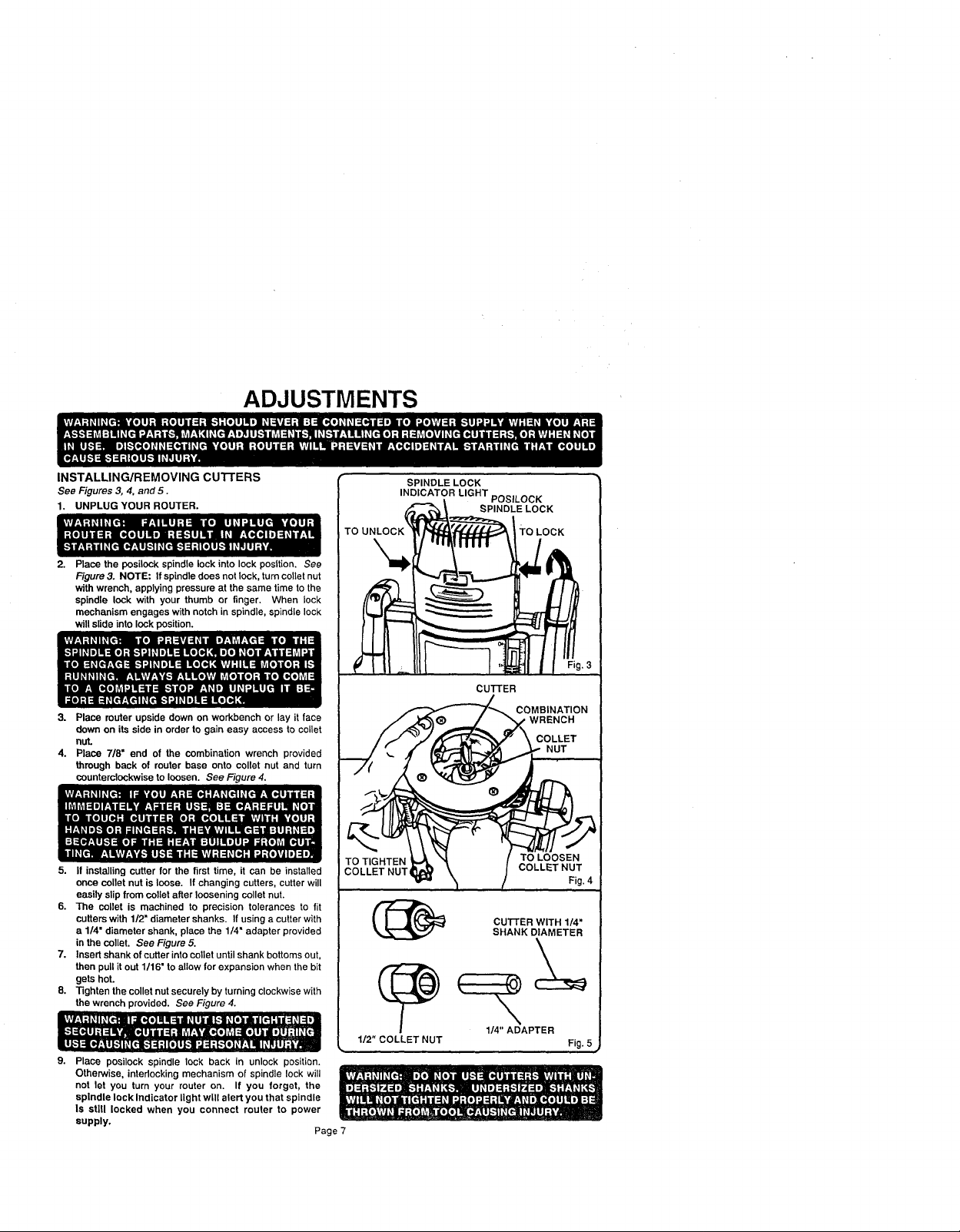
ADJUSTMENTS
INSTALLING/REMOVING cUTrERS
See Figures 3, 4. and 5.
1. UNPLUG YOUR ROUTER.
Place the posileck spindle lock into lock posttion. See
Figure 3. NOTE: If spindle does not lock, turn caller nut
with wrench, applying pressure at the same time to the
spindle lock with your thumb or finger. When lock
mechanism engages with notch in spindle, spindle lock
will slide into lock position.
3. Place router upside down on workbench or lay it face
down on its side in order to gain easy access to collet
nut.
4. Place 7/8= end of the combination wrench provided
through back of router base onto collet nut and turn
counterclockwise to loosen. See Figure 4.
5. If installing cutter for the first time, it can be installed
once ooUetnut is loose. If changing cutters, cutter will
easily slip from oollet after loosening collet nut.
6. The collet is machined to precision tolerances to fit
cutters with 1/2" diameter shanks. If using a cutter with
a 1/4" diameter shank, place the 1/4" adapter provided
in the oollet. See Figure 5.
7. Insert shank of cutter into collet until shank bottoms out,
then pull it out 1/16" to allow for expansion when the bit
gets hot.
8. -righten the collet nut securely by turning clockwise with
the wrench provided. See Figure 4.
9. Place posileck spindle lock back in unlock position.
Otherwise, intedocking mechanism of spindle lock will
not let you turn your router on. If you forget, the
spindle lock Indicator light will alert you that spindle
Is stlU locked when you connect router to power
supply,
Page 7
INDICATOR LIGHT POSILOCK
TO TIGHTEN
COLLET NUT,
1/2" COLLET NUT
SPINDLE LOCK
SPINDLE LOCK
TO LOCK
CuI-rER
COMBINATION
WRENCH
TO LOOSEN
COLLETNUT
CU'I-rER WITH 1/4"
SHANK DIAMETER
1/4" ADAPTER
COLLET
NUT
Fig. 4
Fig. 5
ADJUSTMENTS
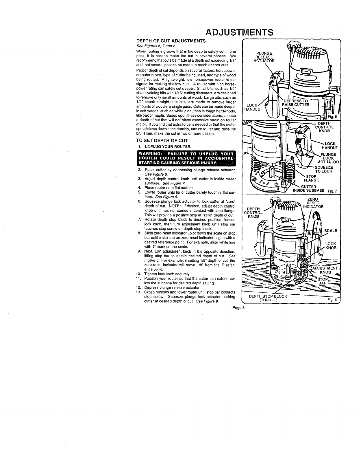
DEPTH OF CUT ADJUSTMENTS
See Figures 6, 7 and 8.
When routing a groove that istoo deep to safely cut inone
pass, it is best to make the cut in several passes. We
recommend that cuts bemade at a depth not exceeding 1/8"
and that several passes be made to reach deeper cuts.
Proper depth of cut depends on several factors: horsepower
of router motor, type of cutter being used, and type of wood
being routed. A lightweight, low horsepower router is de-
signed for making shallow cuts. A router with high horse-
power rating can safely cut deeper. Small bits, such as 1/4"
shank veiningbits with1/16" cuttingdiameters, are designed
to remove only small amounts of wood. Large bits, such as
1/2" shank straight-flute bits, are made to remove larger
amounts ofwood ina single pass, Cuts can be made deeper
in soft woods, such as white pine, than intough hardwoods,
like oak or maple. Based upon these considerations, choose
a depth of cut that will not place excessive strain on router
motor. If you find that extra force is needed or that the motor
speed slows down considerably, turn off router and raise the
bit. Then, make the cut in two or more passes.
TO SET DEPTH OF CUT
1, UNPLUG YOUR ROUTER.
2. Raise cutter by depressing plunge release actuator.
See Figure 6.
3. Adjust depth control knob until cutter is inside router
subbase. See Figure 7.
4. Place router on a flat surface.
5. Lower router until tip of cutter barely touches flat sur-
face. See Figure 8,
6. Squeeze plunge lock actuator to lock cutter at "zero"
depth of cut. NOTE: If desired, adjust depth control
knob until hex nut comes in contact with stop flange.
This will provide a positive stop at "zero" depth of cut.
7. Rotate depth stop block to desired position, loosen
lock knob, then turn adjustment knob until stop bar
touches stop screw on depth stop block.
8. Slide zero-reset indicator up or down the scale on stop
bar until white line on zero-reset indicator aligns with a
desired reference point, For example, align white line
with 1" mark on the scale.
9. Next, turn adjustment knob in the opposite direction,
lifting stop bar to obtain desired depth of cut. See
Figure 8. For example, if setting 1/8" depth of cut, the
zero-reset indicator will move 1/8" from the 1" refer-
ence point.
10. Tighten lock knob securely.
11. Position your router so that the cutter can extend be-
low the subbase for desired depth setting.
12. Depress plunge release actuator.
13, Grasp handles and lower router until stop bar contacts
stop screw. Squeeze plunge lock actuator, locking
cutter at desired depth of cut. See Figure 9.
Page 8
KNOB
PLUNGE
RELEASE
ACTUATOR
(TURRET)
INSIDE SUBBASE
Rg. 7
Fig. 8
 Loading...