

Craftsman 315268350 Owner’s Manual
Operator'sManual
ICRRFTSMRN'I
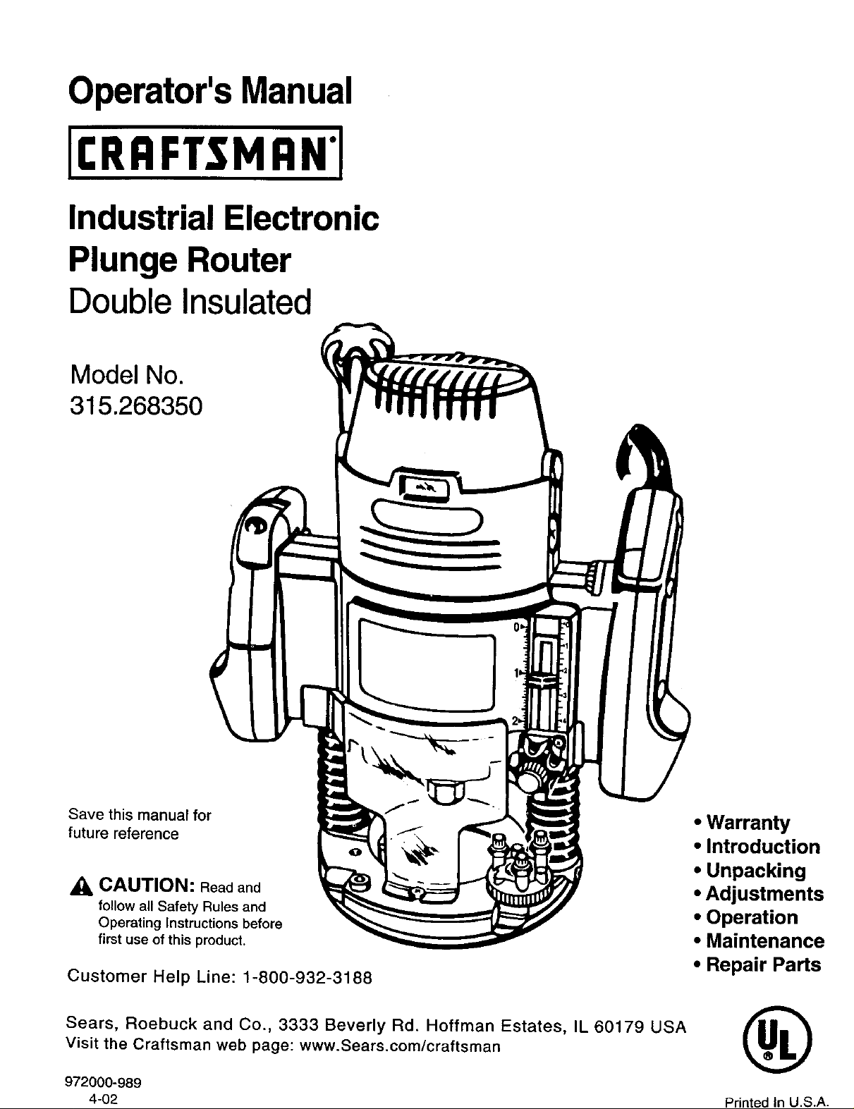
Industrial Electronic
Plunge Router
Double Insulated
Model No.
315.268350
m m
Save this manual for
future reference
f_k_.. • Introduction
_1_CAUTION: Read and
follow all Safety Rules and
Operating Instructions before
first use of this product.
Customer Help Line: 1-800-932-3188
Sears, Roebuck and Co., 3333 Beverly Rd. Hoffman Estates, IL 60179 USA
Visit the Craftsman web page: www.Sears.com/craftsman
972000-989
4-02
• Warranty
• Unpacking
• Adjustments
• Operation
• Maintenance
• Repair Parts
®
Printed In U.S.A.
DOUBLE INSULATION is a safety concept in electric
power tools which eliminates the need for the usual
three wire grounded power cord and grounded
supply system. Wherever there is electric current in
the tool there are two complete sets of insulation to
protect the user. All exposed metal parts are isolated
from internal metal motor components with
protecting insulation.
A
WARNING: The double insulated system is
intended to protect the user from shock resulting
from a break in the tool's internal wiring. Observe
all normal safety precautions related to avoiding
electrical shock.
READ ALLINSTRUCTIONS
IMPORTANT - Servicing of a tool with double
insulation requires extreme care and knowledge of
the system and should be performed only by a
qualified service technician. For service we suggest
you return the tool to your nearest Sears Store for
repair. Always use original factory replacement parts
when servicing.
A
WARNING: Do not attempt to operate this
tool until you have read thoroughly and
understand completely all instructions, safety
rules, etc. contained in this manual. Failure
to comply can result in accidents involving
fire, electric shock, or serious personal
injury. Save operator's manual and review
frequently for continuing safe operation, and
instructing others who may use this tool.
• KNOW YOUR POWER TOOL. Read operator's
manual carefully. Learn its applications and
limitations as well as thespecific potential
hazards related to this tool.
• GUARD AGAINST ELECTRICAL SHOCK by
preventing body contact with grounded surfaces.
For example: Pipes, radiators, ranges,
refrigerator enclosures.
• KEEP GUARDS IN PLACE and in working
order.
• KEEP WORK AREA CLEAN. Cluttered areas
and benches invite accidents.
• AVOID DANGEROUS ENVIRONMENT. Don't
use power tool in damp or wet locations or
expose to rain. Keep work area well lit.
• KEEP CHILDREN AND VISITORS AWAY. All
visitors should wear safety glasses and be kept
a safe distance from work area. Do not let
visitors contact tool or extension cord.
• STORE IDLE TOOLS. When not in use tools
should be stored in a dry and high or locked-up
place - out of the reach of children.
• DON'T FORCE TOOL. It will do the job better
and safer at the rate for which it was designed.
• USE RIGHT TOOL. Don't force small tool or
attachment to do the job of a heavy duty tool.
Don't use tool for purpose not intended - for
example - A circular saw should never be used
for cutting tree limbs or logs.
• WEAR PROPER APPAREL. Do not wear loose
clothing or jewelry that can get caught in tool's
moving parts and cause personal injury. Rubber
gloves and non-skid footwear are recommended
when working outdoors. Wear protective hair
covering to contain long hair and keep it from
being drawn into nearby air vents.
• ALWAYS WEAR SAFETY GLASSES.
Everyday eyeglasses have only impact-resistant
lenses; they are NOT safety glasses.
• PROTECT YOUR LUNGS. Wear a face or dust
mask if operation is dusty.
• PROTECT YOUR HEARING. Wear hearing
protection during extended periods of operation.
• DON'T ABUSE CORD. Never carry tool by cord
or yank it to disconnect from receptacle. Keep
cord from heat, oil and sharp edges.
• SECURE WORK. Use clamps or a vise to hold
work. Both hands are needed to operate the
tool.
• DON'T OVERREACH. Keep proper footing and
balance at all times. Do not use on a ladder or
unstable support.
• MAINTAIN TOOLS WITH CARE. Keep tools
sharp at all times, and clean for best and safest
performance. Follow instructions for lubricating
and changing accessories.
• DISCONNECT TOOLS. When not in use, before
servicing, or when changing attachments,
blades, bits, cutters, etc., all tools should be
disconnected from power supply.
• REMOVE ADJUSTING KEYS AND
WRENCHES. Form habit of checking to see that
keys and adjusting wrenches are removed from
tool before turning it on.
Look for this symbol to point out important safety precautions.
It means attention!!! Your safety is involved.

• AVOID ACCIDENTAL STARTING. Don't carry
plugged-in tools with finger on switch. Be sure
switch is off when plugging in.
• MAKE SURE YOUR EXTENSION CORD IS IN
GOOD CONDITION. When using an extension
cord, be sure to use one heavy enough to carry
the current your productwill draw. An
undersized cord will cause a drop in line voltage
resulting in loss of power and overheating. A
wire gage size (A.W.G.) of at least 14 is
recommended for an extension cord 25 feet or
less inlength. A cord exceeding 25 feet is not
recommended. If indoubt, use the next heavier
gage. The smaller the gage number, the
heavier the cord.
• OUTDOOR USE EXTENSION CORDS. When
tool is used outdoors, use only extension cords
suitable for use outdoors. Outdoor approved
cords are marked with the suffix W-A, for
example - SJTW-A or SJOW-A.
• KEEP CUTTERS CLEAN AND SHARP. Sharp
cutters minimize stalling and kickback.
• KEEP HANDS AWAY FROM CUTFING AREA.
Keep hands away from cutters. Do not reach
underneath work while cutter is rotating. Do not
attempt to remove material while cutter is
rotating.
• NEVER USE IN AN EXPLOSIVE
ATMOSPHERE. Normal sparking of the motor
could ignitefumes.
• INSPECT TOOL CORDS PERIODICALLY and
if damaged, have repaired at your nearest
Sears Repair Center. Stay constantly aware of
cord location.
• INSPECT EXTENSION CORDS PERIODI-
CALLY and replace if damaged.
• KEEP HANDLES DRY, CLEAN, AND FREE
FROM OIL AND GREASE. Always use a clean
cloth when cleaning. Never use brake fluids,
gasoline, petroleum-based products or any
strong solvents to clean your tool.
• STAY ALERT. Watch what you are doing and
use common sense. Do not operate tool when
you are tired. Do not rush.
• CHECK DAMAGED PARTS. Before further use
of the tool, a guard or other part that is dam-
aged should be carefully checked to determine
that itwill operate properly and perform its
intended function. Check for alignment of
moving parts, bindingof moving parts, break-
age of parts, mounting, and any other condi-
tions that may affect itsoperation. A guard or
other part that is damaged should be properly
repaired or replaced by an authorized service
center unless indicated elsewhere in this
instructionmanual.
• DO NOT USE TOOL IF SWITCH DOES NOT
TURN IT ON AND OFF. Have defective
switches replaced by an authorized service
center.
• INSPECT FOR and remove all nails from
lumber before muting.
• DRUGS, ALCOHOL, MEDICATION. Do not
operate tool while under the influence of drugs,
alcohol, or any medication.
• WHEN SERVICING USE ONLY IDENTICAL
CRAFTSMAN REPLACEMENT PARTS.
• POLARIZED PLUGS. To reduce the riskof
electricshock, thistool has a polarized plug
(one blade iswider than the other). This plug
will fit in a polarized outletonly one way. Ifthe
plugdoes not fit fully in the outlet, reverse the
plug. If itstill does not fit, contact a qualified
electdcian to installthe proper outlet. Do not
change the plug in any way.
• DO NOT USE TOOL UNDER "BROWN-OUT"
OR OTHER LOW VOLTAGE CONDITIONS.
Also, do not use with any device that could
cause the power supply voltage to change.
• WHEN USING THIS ROUTER WITH A
ROUTER TABLE, HELP PREVENT POS-
SIBLE SERIOUS INJURY BY KEEPING THE
CUTTER GUARDED AT ALL TIMES. Use only
router tables, with guards, that have been
designed for use on routersthat are of this
type, size, and weight.
• SAVE THESE INSTRUCTIONS. Review them
frequently and use them to instructothers who
may use thistool. Ifyou loan someone this
tool, loan them these instructions also.
,a,
Your risk from these exposures varies, depending on
how often you do this type of work. To reduce your
exposure to these chemicals: work in a well ventilated
area, and work with approved safety equipment, such
as those dust masks that are specially designed to
filter out microscopic particles.
WARNING: Some dust created by power
sanding, sawing, grinding, drilling, and other
construction activities contains chemicals
known to cause cancer, birth defects or other
reproductive harm. Some examples of these
chemicals are:
• lead from lead-based paints,
• crystalline silica from bricks and cement and other
masonry products, and
• arsenic and chromium from chemically-treated
lumber.
CONGRATULATIONS AND THANK YOU FOR BUYING
THIS CRAFTSMAN ROUTER. It has been designed,
engineered and manufactured to provide you with Sears
high standard of dependability, ease of operation, and
operator safety. Properly cared for, it will give you years of
rugged, trouble-frae performance.
SPECIFICATIONS:
Depth Of Cut 0-2-1/2 in.
Collet 1/2 in.
A
Your muter has many features for making muting
operations more pleasant and enjoyable. Safety,
performance and dependability have been given top
pdority in the design of this muter making iteasy to
maintain and operate.
CAUTION: Carefully read through this entire
operator's manual before using your new muter.
Pay close attention to the Rules For Safe
Operation, Wamings and Cautions. If you use
your muter propedy and only for what it is
intended, you will enjoy years of safe, reliable
service.
FULL ONE YEAR WARRANTY ON CRAFTSMAN INDUSTRIAL ELECTRONIC PLUNGE ROUTER
If this Craftsman Industrial Electronic Plunge Router fails due to a defect in material or workmanship within one year
from the date of purchase, Sears will repair itfree of charge.
WARRANTY SERVICE IS AVAILABLE BY SIMPLY RETURNING THE TOOL TO THE NEAREST SEARS STORE
IN THE UNITED STATES.
This warranty gives you specific legal rights,and you may also have other dghts which vary from state to state.
SEARS, ROEBUCK AND CO.
DEPT. 817 WA
HOFFMAN ESTATES, iL 60179
Adapter 1/4 in.
Horsepower 3.5
Rating 120 volts, 60 Hz, AC only, 15.0 AMPS
No Load Speed 10,000 - 22,000 RPM
Power Cord 10 Ft.
I Net Weight 12.8 Lbs.
_,
1. Rules for Safe Operation ............................................................................ 2-3
2. Introduction and Product Specifications ......................................................... 4
3. Warranty and Table Of Contents .................................................................... 4
4. Unpacking ...................................................................................................... 5
5. Features ...................................................................................................... 5-7
6. Adjustments .............................................................................................. 8-12
7. Operation ................................................................................................ 13-18
8. Maintenance ........................................................................................... 19-23
9. Exploded View and Repair Parts List...................................................... 24-25
10. Parts Ordering / Service ............................................................................... 26
Your new plunge router comes fully assembled. After removing it from the box, inspect itcarefully to make sure that itis
not damaged and that no parts are missing. See Figure 1. The following accessodes should also be included in the box:
1. 15/16 in. Wrench =,_
2. 1/4 in. Adapter
Your electronic router is a versatile woodworking tool which will give you years of trouble-free performance. It is engi-
neered with the professional in mind, but its ease of operation allows the amateur to produce work which is beautiful and
precise.
3.5 HORSEPOWER MOTOR
Your router has a powerful 3.5 horsepower motor with
sufficient power to handle the toughest routingjobs. The
motor also has extemally accessible brushes for ease of
servicing.
SOFT START
The soft start feature builds motor RPM gradually to
minimize start-up torque. Pressing or releasing the "on-
off"tdgger will turn your router on oroff.
DEPTH CONTROL KNOB
A large depth control knob makes precise depth of cut
changes possible. It also is very helpful when making
depth of cut changes with your router mounted upside
down on a router table.
Your router is equipped with a "lock-on" feature that is
convenient when continous operation for extended
periods of time is required.
Your router has large oversized handles for easy handling
and maintaining proper control when routing. The left
handle allows you to set cutter depth of cutwhen making
to the "on-off" trigger, "lock-on" button, and vadable speed
control selector. The handles have also been designed so
that they are comfortable and easy to grasp when
WARNING: Ifany parts are missing, do not
operate your router untilthe missing parts are
replaced. Failure to do so could result in
possible sedous personal injury.
"LOCK-ON" FEATURE"
LARGE HANDLES
plunge cuts, while the right handle provides easy access
operating in different positions or at different angles.
VARIABLE SPEED SWITCH WITH
DEPTH STOP SYSTEM
The depth stop block located on the base of your router
provides three adjustable stops and three fixed stops for
quick depth of cut changes. A depth adjustment scale
makes quick adjustments to depth of cut changes pos-
sible. The spring loaded adjustment knob quick releases
stop bar by depressing center of knob.
1/4 IN. AND 1/2 IN. SHANK CAPACITY
Your router has a 1/2 in. diameter collet that accepts
cutters with 1/2 in. shanks. A 1/4 in. adapter has been
provided so that cutters with 1/4 in. shank bitscan also be
used.
CHIP SHIELD
A clear plastic see-through chip shield has been provided
on the base of your routerfor protection against flying
dust and chips. It is designed to fit the front opening of the
router base.
POSILOCK SPINDLE LOCK
A posilock spindle lock secures the spindle so that only
one wrench is needed to loosen collet nut and change
cutters. A spindle lock indicatorlight alerts you that
spindle is locked if you connect router to power supply
before unlocking spindle. Note: Your router will not run if
spindle is locked.
ELECTRONIC SPEED CONTROL
(Feedback Switch)
Your router has advanced electronic features, designed to
assist you in getting the maximum use from your router.
By making proper speed selections, your router can be
adjusted to specfic routing needs. This eliminates much of
the guess work previously needed to perform a given job.
Both the experienced and inexperienced router users
benefit, obtaining professional like results with fewer job
errors.
The variable speed control allows the router speed to be
adjusted from 10,000 to 22,000 rpm. The variable speed
control selelctor is conveniently located inside the dght
handle near the operator's thumb or hand.
The electronic feature of your router introduces the
flexibility of adjusting the motor speed to requiredjob
conditions. An electronic speed control module senses the
load applied to the motor, and increases or decreases
motor voltage to compensate for and maintain desired
RPM
Speed can be set according to the approximate cutter
diameter you will be using and to the hardness of the
material being cut. The best cuts are made when the
cutter is fed through material at the proper rate of feed.
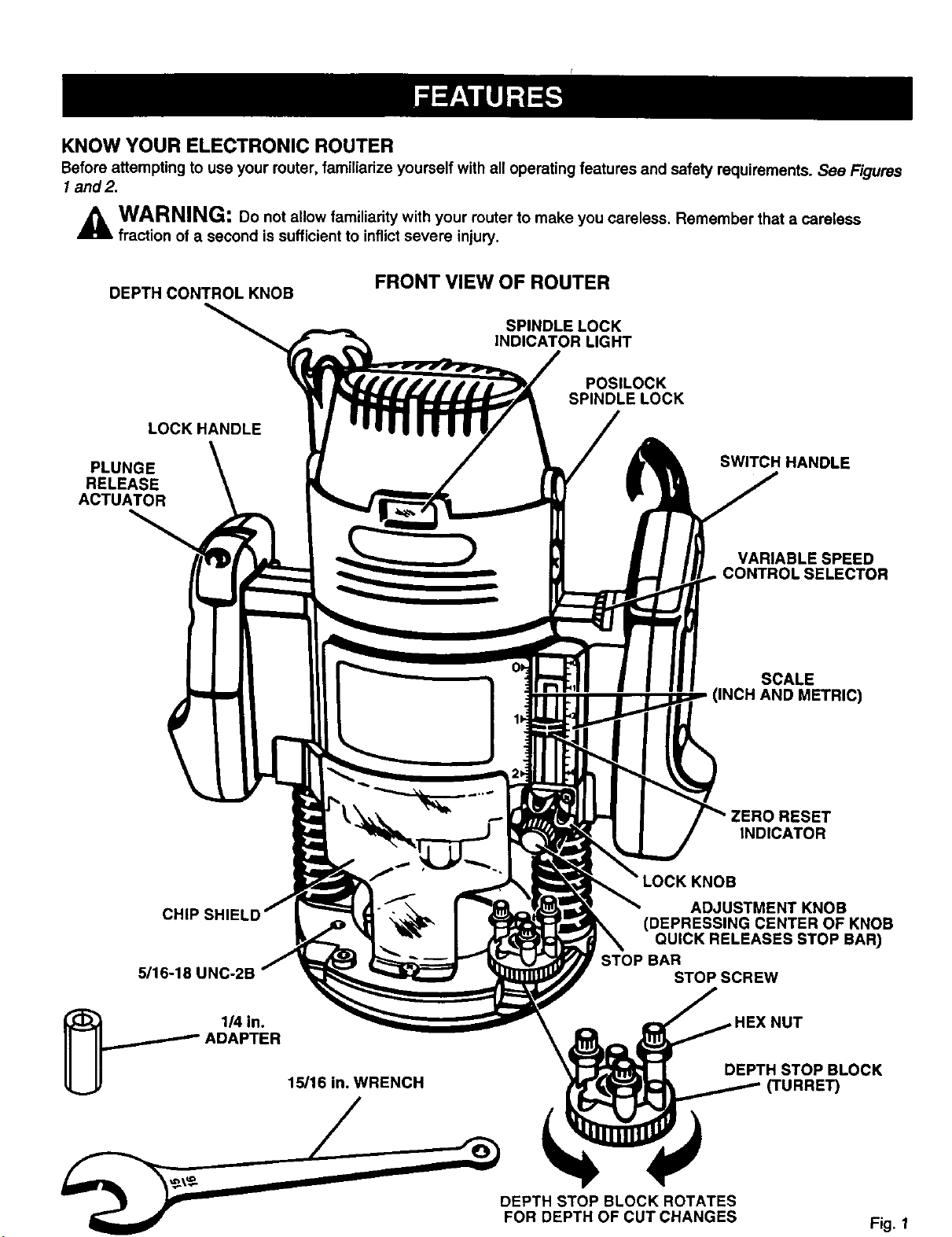
KNOW YOUR ELECTRONIC ROUTER
Beforeattemptingto useyourrouter,familiarize yourselfwithalloperatingfeatures and safetyrequirements.See Figures
1and2.
WARNING: Do not allow familiarity with your router to make you careless, Remember that a careless
fraction of a second is sufficient to inflict severe injury.
DEPTH CONTROL KNOB
LOCKHANDLE
PLUNGE
RELEASE
ACTUATOR
FRONT VIEW OF ROUTER
SPINDLE LOCK
INDICATOR LIGHT
POSILOCK
SPINDLE LOCK
SWITCH HANDLE
VARIABLE SPEED
CONTROLSELECTOR
SCALE
(INCH AND METRIC)
CHIP SHIE
5/16-18 I
ADAPTER
1/4 in.
15/16 in. WRENCH
ADJUSTMENT KNOB
(DEPRESSING CENTER OF KNOB
QUICK RELEASES STOP BAR)
STOP BAR
STOP SCREW
DEPTH STOP BLOCK ROTATES
FOR DEPTH OF CUT CHANGES
RESET
INDICATOR
NUT
DEPTH STOP BLOCK
_URRE_
Fig. 1
CONTROL SELECTOR
POWER CORD
"LOCK-ON'
BUTTON
"ON-OFF
TRIGGER
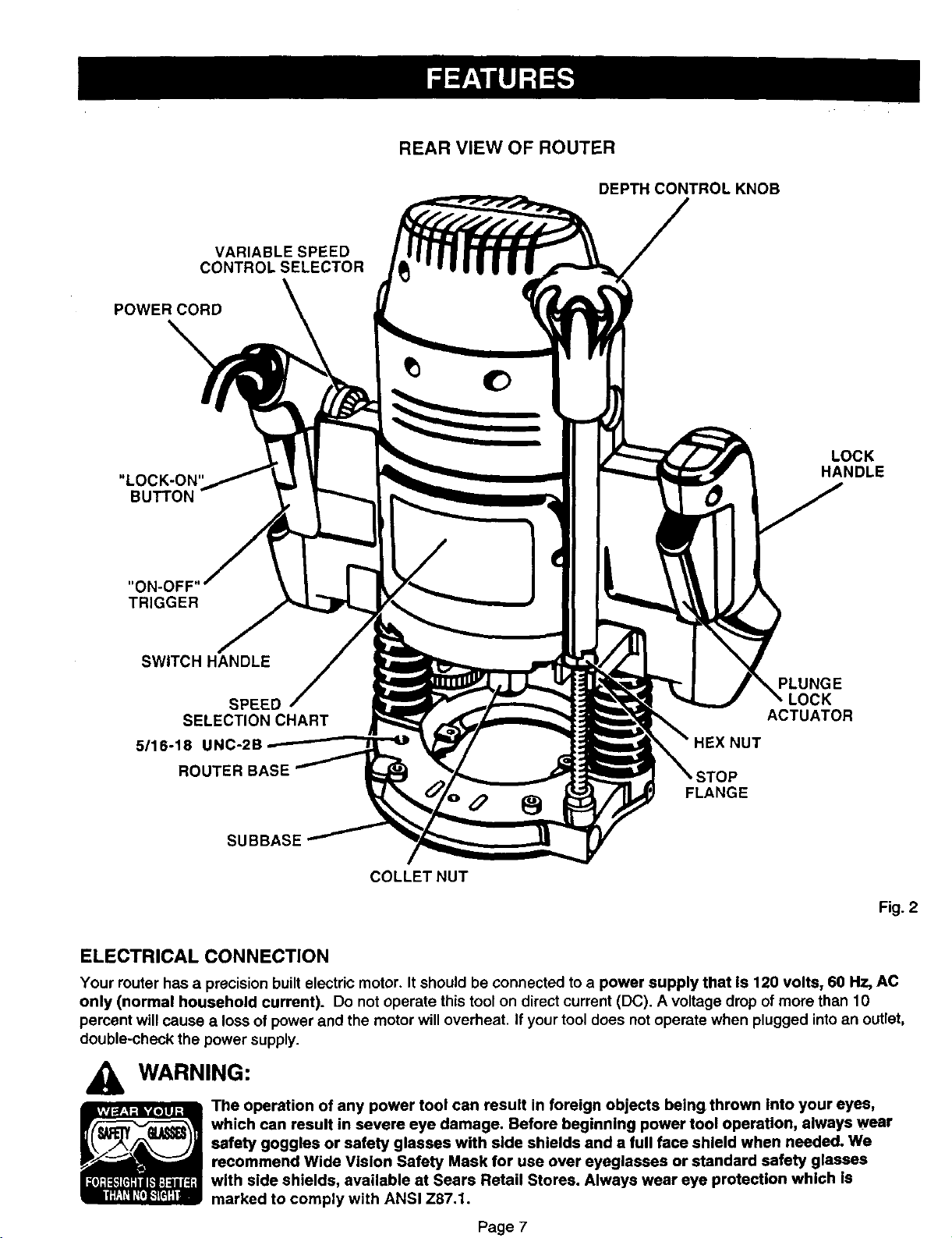
REAR VIEW OF ROUTER
DEPTH CONTROLKNOB
VARIABLE SPEED
LOCK
HANDLE
SWITCH HANDLE
PLUNGE
SPEED
SELECTION CHART
5116-18 UNC-2B
ROUTER BASE
FLANGE
SUBBASE
COLLETNUT
ACTUATOR
Fig. 2
ELECTRICAL CONNECTION
Your router has a precision built electric motor. It should be connected to a power supply that Is 120 volts, 60 Hz, AC
only (normal household current). Do not operate this tool on direct current (DC). A voltage drop of more than 10
percent will cause a loss of power and the motor will overheat. If your tool does not operate when plugged into an outlet,
double-check the power supply.
WARNING:
The operation of any power tool can result in foreign objects beingthrown into your eyes,
which can result in severe eye damage. Before beginning power tool operation, always wear
safety goggles or safety glasses with side shields and a full face shield when needed. We
recommend Wide Vision Safety Mask for use over eyeglasses or standard safety glasses
with side shields, available at Sears Retail Stores. Always wear eye protection which Is
marked to comply with ANSI Z87.1.
Page 7
WARNING: Your router should never be
A
connected to power supply when you are
assembling parts, making adjustments,
installing or removing cutters, or when not in
use. Disconnecting your router will prevent
accidental starting that could cause sedous
injury.
INSTALLING/REMOVING CUTrERS
See Figures 3, 4, and 5.
• UNPLUG YOUR ROUTER.
WARNING: Failure to unplug your router
could result in accidental starting causing serious
injury.
TO
SPINDLE LOCK
INDICATOR LIGHT POSILOCK
SPINDLE LOCK
TOLOCK
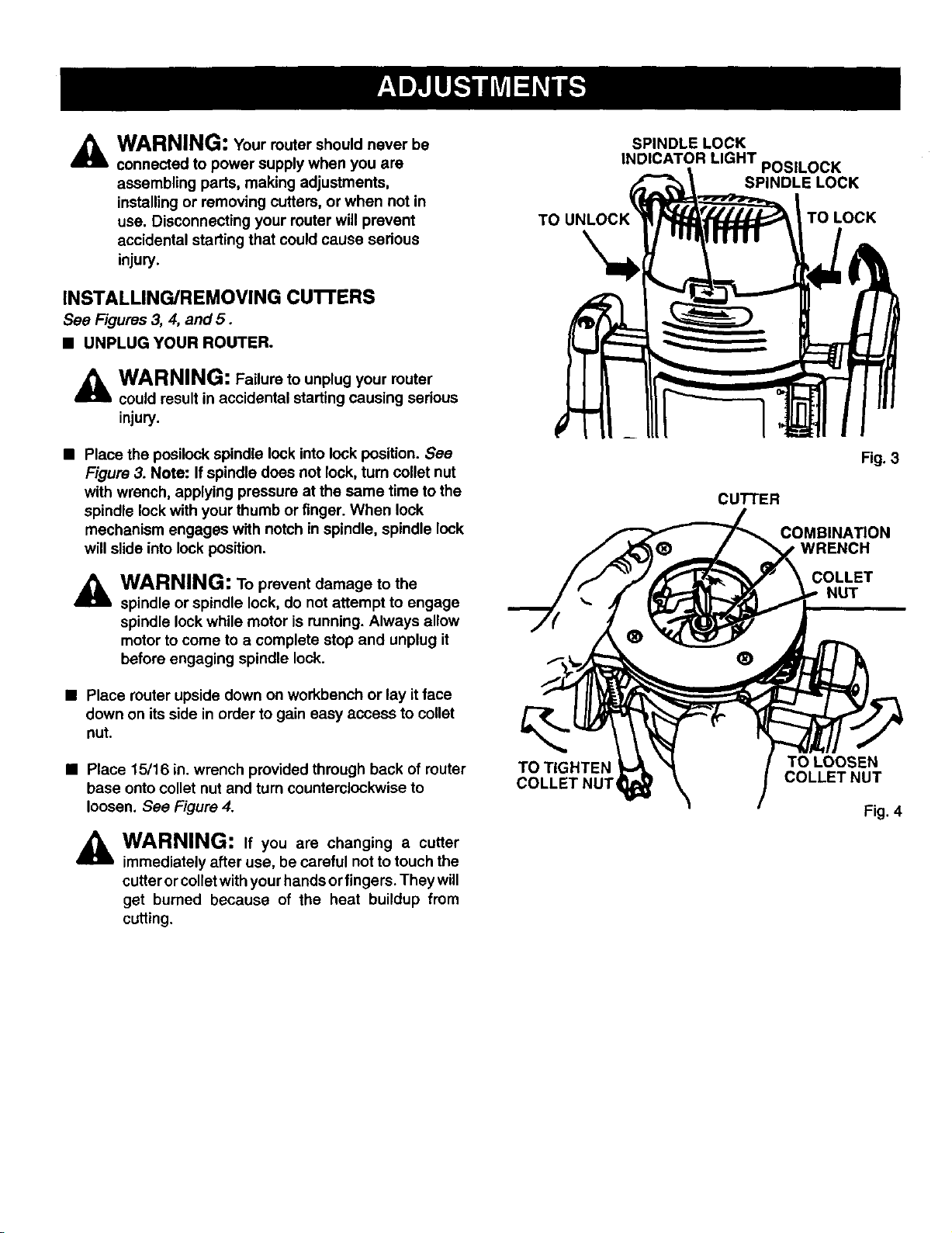
• Place the posilockspindle lock into lock position. See
Figure 3. Note: If spindle does not lock, turn collet nut
with wrench, applying pressure at the same time to the
spindle lockwith your thumb or finger. When lock
mechanism engages with notch in spindle, spindle lock
will slide into lock position.
WARNING: To prevent damage to the
A
spindle or spindle lock, do not attempt to engage
spindle lock while motor is running. Always allow
motor to come to a complete stop and unplug it
before engaging spindle lock.
• Place router upside down on workbench or lay it face
down on its side in order to gain easy access to collet
nut.
• Place 15/16 in. wrench provided through back of router
base onto collet nut and turn counterclockwise to
loosen, See Figure 4.
WARNING: If you are changing a cutter
A
immediately after use, be careful not to touch the
cutter or colletwith yourhands or fingers. They will
get burned because of the heat buildup from
cutting.
TO TIGHTEN
COLLET NUT,
Fig. 3
CUTTER
COMBINA_ON
WRENCH
COLLET
NUT
®
TO LOOSEN
COLLET NUT
Fig. 4
INSTALLING/REMOVING CUI"I'ERS
(Continued)
• If installing cutter for the first time, it can be installed
once collet nut is loose. If changing cutters, cutter will
easily slip from collet after loosening collet nut.
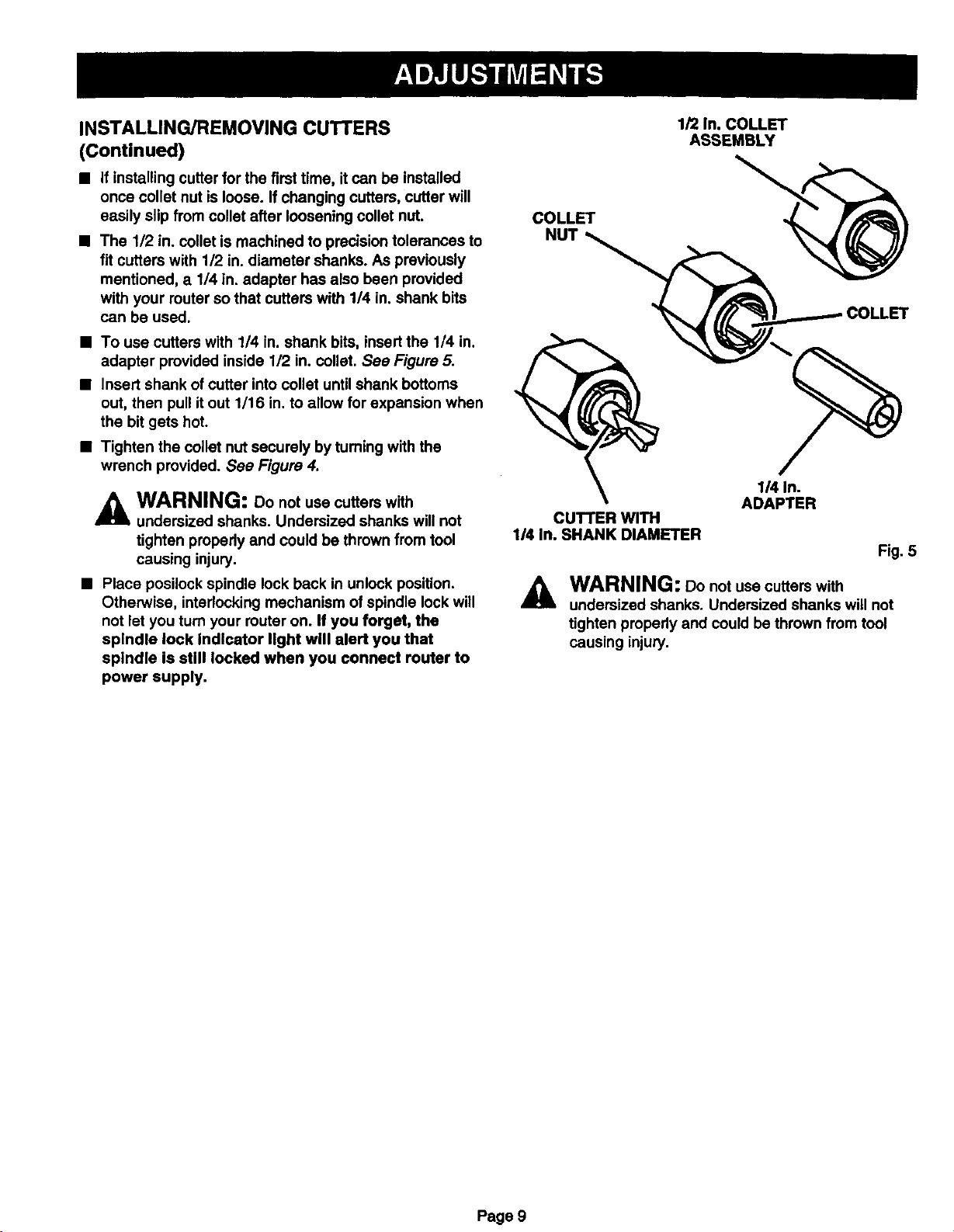
• The 112in. collet is machined to precision tolerances to
fit cutters with 1/2 in. diameter shanks. As previously
mentioned, a 1/4 in. adapter has also been provided
with your router so that cutters with 1/4 in. shank bits
can be used.
• To use cutters with 1/4 in. shank bits, insert the 1/4 in.
adapter provided inside 1/2 in. collet. See Figure 5.
• Insert shank of cutter into collet untilshank bottoms
out, then pull it out 1/16 in. to allow for expansion when
the bit gets hot.
• Tighten the collet nut securely by turning with the
wrench provided. See Figure 4.
WARNING: Do not use cutters with
undersized shanks. Undersized shanks will not
tighten properly and could be thrown from tool
causing injury,
• Place posilock spindle lock back inunlock position.
Otherwise, interlocking mechanism of spindle lock will
not let you turn your routeron. If you forget, the
spindle lock Indicator light will alert you that
spindle is still locked when you connect router to
power supply.
1/2 In. COLLET
COLLET
CUTTER WITH
1/4 In. SHANK DIAMETER
WARNING: Do not use cutters with
A
undersized shanks. Undersized shanks will not
tighten properly and could be thrown from tool
causing injury,
ASSEMBLY
1/4 In.
ADAPTER
Fig. 5
Page 9
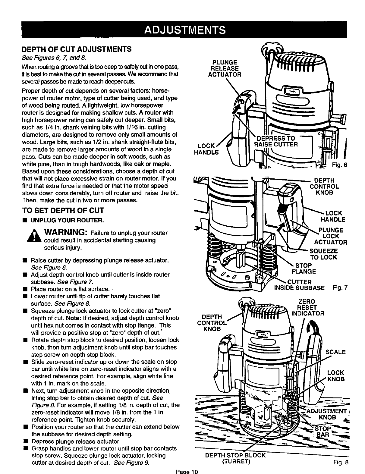
DEPTH OF CUT ADJUSTMENTS
See Figures 6, 7, and 8.
When routinga groovethatistoodeep to safelycutinone pass,
itis bestto make thecut inseveralpasees.We recommendthat
severalpassesbe made to reachdeepercuts.
Proper depth of cut depends on several factors: horee-
power of router motor, type of cutter being used, and type
of wood being routed. A lightweight, low horsepower
router is designed for making shallow cuts. A router with
high horsepower rating can safely cut deeper. Small bits,
such as 1/4 in. shank veining bits with 1/16 in. cutting
diameters, are designed to remove only small amounts of
wood. Large bits, such as 1/2 in. shank straight-flute bits,
are made to remove larger amounts of wood in a single
pass. Cuts can be made deeper in soft woods, such as
white pine, than in tough hardwoods, like oak or maple.
Based upon these considerations, choose a depth of cut
that will not place excessive strain on router motor. If you
find that extra force is needed or that the motor speed
slows down considerably, turn off router and raise the bit.
Then, make the cut in two or more passes.
TO SET DEPTH OF CUT
• UNPLUG YOUR ROUTER.
WARNING: Failure to unplug your router
could result in accidental starting causing
serious injury.
• Raise cutter by depressing plunge release actuator.
See Figure 6.
• Adjust depth control knob untilcutter is inside router
subbase. See Figure 7.
• Place router on a flat surface..
• Lower router until tip of cutter barely touches flat
surface. See Figure 8.
• Squeeze plunge lockactuator to lock cutter at "zero"
depth of cut. Note: If desired, adjust depth control knob
until hex nut comes in contact with stop flange. This
will provide a positivestop at "zero" depth ofcut.'
• Rotate depth stop block to desired position, loosen lock
knob, then turn adjustment knob until stop bar touches
stop screw on depth stop block.
• Slide zero-reset indicator up or down the scale on stop
bar until white line on zero-reset indicator aligns with a
desired reference point. For example, align white line
with 1 in. mark on the scale.
• Next, turn adjustment knob in the opposite direction,
lifting stop bar to obtain desired depth of cut. See
Figure 8. For example, if setting 1/8 in. depth of cut, the
zero-reset indicator will move 1/8 in. from the 1 in.
reference point. Tighten knob securely.
• Position your router so that the cutter can extend below
the subbase for desired depth setting.
• Depress plunge release actuator.
• Grasp handles and lower router until stop bar contacts
stop screw. Squeeze plunge lock actuator, locking
cutter at desired depth of cut. See Figure 9.
Paoe 10
PLUNGE
RELEASE
ACTUATOR
HANDLE
DEPTH
KNOB
DEPTH STOP BLOCK
(TURRET)
/
Fig. 6
DEPTH
CONTROL
KNOB
HANDLE
PLUNGE
LOCK
ACTUATOR
SQUEEZE
TO LOCK
STOP
FLANGE
INSIDE SUBBASE Fig. 7
ZERO
RESET
INDICATOR
SCALE
LOCK
KNOB
Fig. 8
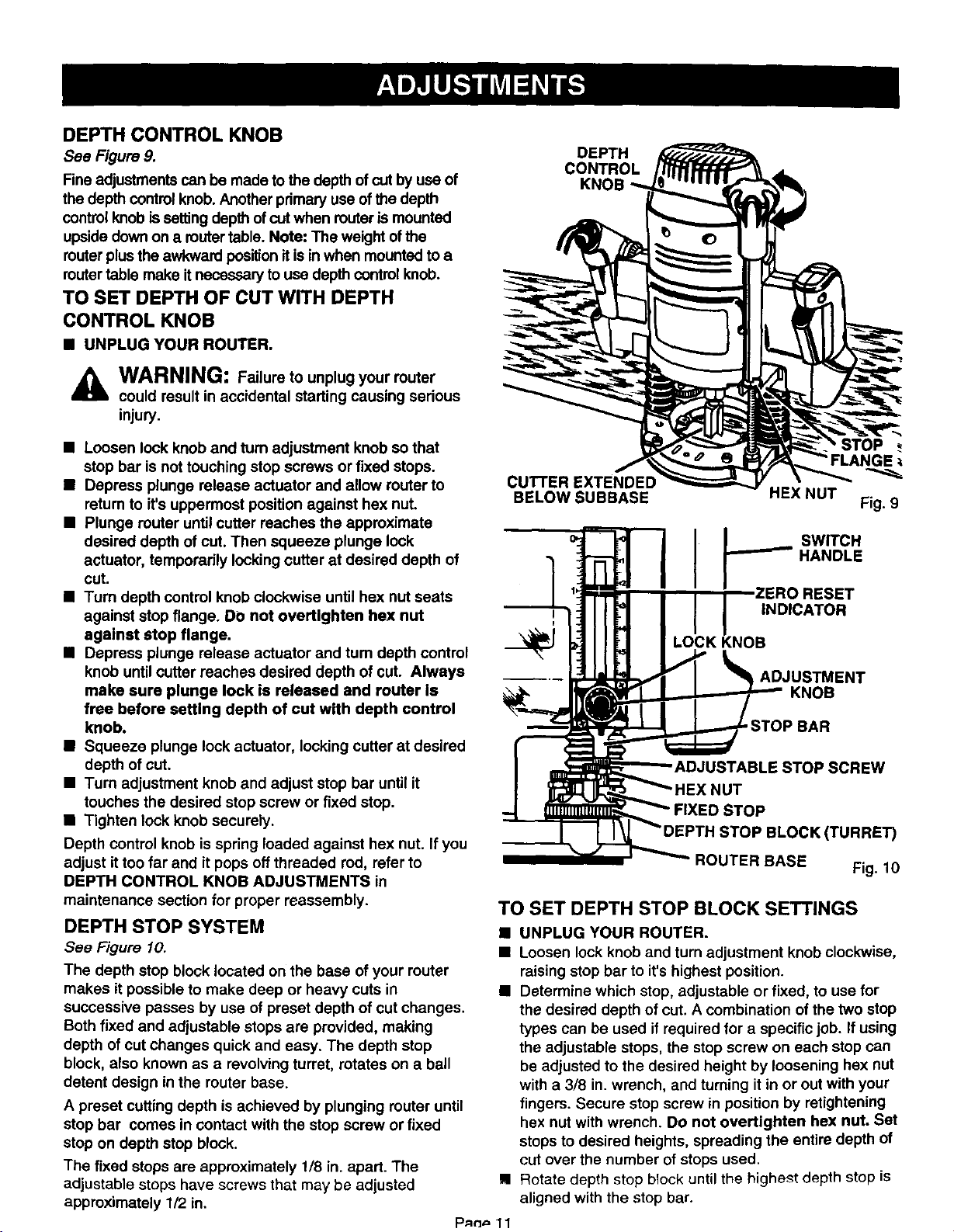
DEPTH CONTROL KNOB
See Figure 9.
Fine adjustments can be made to the depth of cut by use of
the depth control knob. Another primary use of the depth
controlknob is settingdepth of cut when router is mounted
upside downon a router table. Note: The weight of the
router plusthe awkward positionit is in when mounted to a
router table make itnecessary to use depthcontrol knob.
TO SET DEPTH OF CUT WITH DEPTH
CONTROL KNOB
B UNPLUG YOUR ROUTER.
WARNING: Failure to unplug your router
could result in accidental starting causing serious
injury.
DEPTH
CONTROL
B Loosen lock knob and turn adjustment knob so that
stop bar is not touching stop screws or fixed stops.
• Depress plunge release actuator and allow router to
retum to it's uppermost position against hex nut.
• Plunge router until cutter reaches the approximate
desired depth of cut. Then squeeze plunge lock
actuator, temporarily locking cutter at desired depth of
cut.
• Turn depth control knob clockwise until hex nut seats
against stop flange. DO not overtlghten hex nut
against stop flange.
• Depress plunge release actuator and turn depth control
knob untilcutter reaches desired depth of cut. Always
make sure plunge lock is released and router Is
free before setting depth of cut with depth control
knob.
• Squeeze plunge lockactuator, locking cutter at desired
depth of cut.
• Turn adjustment knob and adjust stop bar until it
touches the desired stop screw or fixed stop.
• Tighten lock knob securely.
Depth control knob is spring loaded against hex nut. If you
adjust ittoo far and it pops off threaded rod, refer to
DEPTH CONTROL KNOB ADJUSTMENTS in
maintenance section for proper reassembly.
DEPTH STOP SYSTEM
See Figure 10.
The depth stop block located on the base of your router
makes it possible to make deep or heavy cuts in
successive passes by use of preset depth of cut changes.
Both fixed and adjustable stops are provided, making
depth of cut changes quick and easy. The depth stop
block, also known as a revolving turret, rotates on a ball
detent design in the router base.
A preset cutting depth is achieved by plunging router until
stop bar comes in contact with the stop screw or fixed
stop on depth stop block.
The fixed stops are approximately 1/8 in. apart. The
adjustable stops have screws that may be adjusted
approximately 1/2 in,
STOP
CUTTER EXTENDED
BELOW SUBBASE
HEX NUT
Fig. 9
SWITCH
HANDLE
I
ESET
I
;K KNOB
D STOP
ROUTER BASE Fig. 10
TO SET DEPTH STOP BLOCK SETTINGS
• UNPLUG YOUR ROUTER.
• Loosen lock knob and turn adjustment knob clockwise,
raisingstop bar to it's highest position.
• Determine which stop, adjustable or fixed, to use for
the desired depth of cut. A combination of the two stop
types can be used if required for a specific job. If using
the adjustable stops, the stop screw on each stop can
be adjusted to the desired height by loosening hex nut
with a 3/8 in. wrench, and turning it in or out with your
fingers. Secure stop screw in position by retightening
hex nut with wrench. Do not overtighten hex nut. Set
stops to desired heights, spreading the entire depth of
cut over the number of stops used.
Rotate depth stop block until the highest depth stop is
aligned with the stop bar.
INDICATOR
ADJUSTMENT
KNOB
STOP BAR
E STOP SCREW
JT
STOP BLOCK(TURRE_
DEPTH STOP SYSTEM (Continued)
• Raise cutter by depressing plunge release actuator.
• Place router on flat surface, and lower router untiltip of
cutter barely touches flat surface.
• Squeeze plunge lock actuator to lock cutter at "zero"
depth of cut.
• Turn adjustment knob counterclockwise to lower stop
bar against the stop, then tighten lock knob securely.
The highest stop now becomes the "zero' depth of cut
setting.
• Depress plunge release actuator and raise router.
Rotate stop block so that next highest depth stop aligns
with stop bar. This locates cutter for the initial pass.
• Rotate depth stop block after each pass. Make as many
sucessive passes as needed to obtain desired depth of
cut, progressively lowering router to next depth of cut
setting witheach pass.
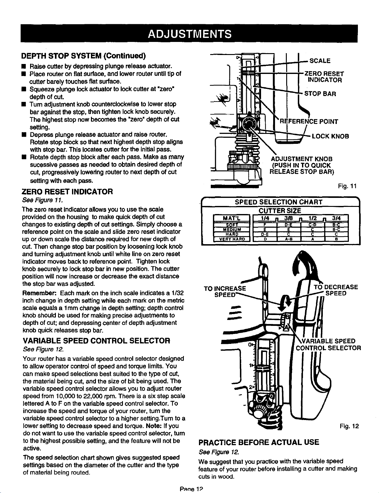
ZERO RESET INDICATOR
See Figure 11.
The zero reset indicator allows you to use the scale
provided on the housing to make quick depth of cut
changes to existing depth of cut settings. Simply choose a
reference point on the scale and slide zero reset indicator
up or down scale the distance required for new depth of
cut. Then change stop bar positionby loosening lock knob
and turning adjustment knob until white line on zero reset
indicator moves back to reference point. Tighten lock
knob securely to lock stop bar in new position. The cutter
position will now increase or decrease the exact distance
the stop bar was adjusted.
Remember: Each mark on the inch scale indicates a 1/32
inch change in depth setting while each mark on the metdc
scale equals a lmm change in depth setting; depth control
knob should be used for making precise adjustments to
depth of cut; and depressing center of depth adjustment
knob quick releases stop bar.
VARIABLE SPEED CONTROL SELECTOR
See Figure 12.
Your router has a variable speed control selector designed
to allow operator control of speed and torque limits.You
can make speed selections best suited to the type of cut,
the material being cut, and the size of bit being used. The
variable speed controlselector allows you to adjust router
speed from 10,000 to 22,000 rpm. There isa six step scale
lettered A to F on the vadable speed control selector. To
increase the speed and torque of your router, turn the
vadable speed control selector to a higher setting.Turn to a
lower setting to decrease speed and torque. Note: If you
do not want to use the vadable speed control selector, turn
to the highest possible setting, and the feature will not be
active.
The speed selection chart shown gives suggested speed
settings based on the diameter ofthe cutter and the type
of material being routed.
RESET
INDICATOR
-STOP BAR
)E POINT
ADJUSTMENT KNOB
(PUSHIN TO QUICK
RELEASE STOP BAR)
Fig. 11
SPEED SELECTION CHART
CUTTER SIZE
I MAT'L II I/4 . 3/8. ,/2 n 3/41
SOFT I I F I D'E I C-D I R'C I
I MED,U. II E I E I _ I s-¢ I
I HARP II O-E I c I c; I c I
I VERY HARD I I D I A-B I A I B I
TOINCREASE TO DECREASE
CONTROLSELECTOR
Fig. 12
PRACTICE BEFORE ACTUAL USE
See Figure 12.
We suggest that you practice with the vadable speed
feature of your router before installing a cutter and making
cutsin wood.
PAne 1;)
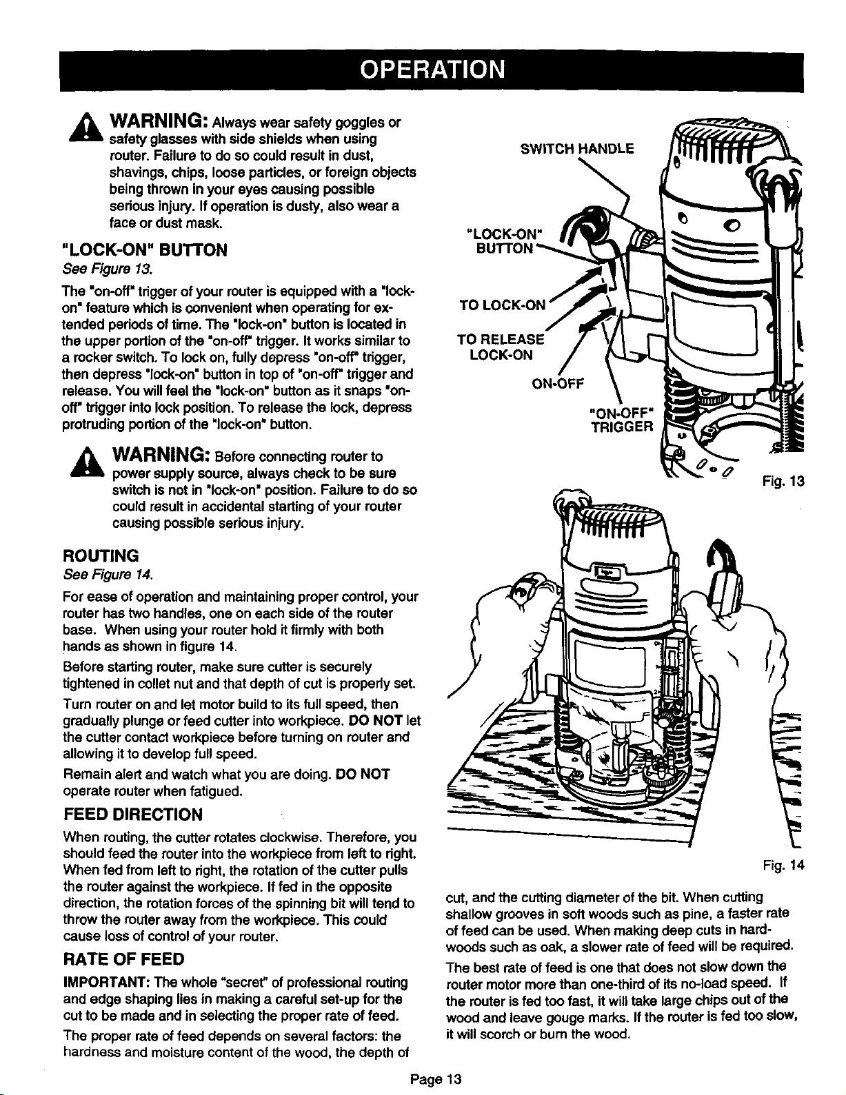
WARNING: Always wear safety goggles or
A
safety glasses with side shields when using
router. Failure to do so could result in dust,
shavings, chips, loose particles, or foreign objects
being thrown in your eyes causing possible
sedous injury. If operation isdusty, also wear a
face or dust mask.
"LOCK-ON" BUTTON
See Figure 13.
The "on-off"trigger of your muter is equipped with a "lock-
on"feature which is convenient when operating for ex-
tended pedods of time. The "look-on"button is located in
the upper portionof the "on-off"tdgger. It works similar to
a rocker switch. To lock on, fully depress "on-off"tdgger,
then depress 'lock-on" button in top of "on-o_ tdgger and
release. You willfeel the "lock-on"button as itsnaps "on-
off' tdgger into lock position. To release the lock, depress
protruding portion of the 'lock-on" button.
SWITCH HANDLE
TO RELEASE
LOCK-ON
ON-OFF
"ON-OFF"
TRIGGER
A
ROUTING
See Figure 14.
For ease of operationand maintaining proper control, your
router has two handles, one on each side of the router
base. When using your router holdit firmly with both
hands as shown in figure 14.
Before startingrouter, make sure cutter is securely
tightened in collst nut and that depth of cut is propedy set.
Turn router on and let motor build to itsfull speed, then
gradually plunge or feed cutter intoworkpiece. DO NOT let
the cutter contact workpiece before turning on muter and
allowing it to develop full speed.
Remain alert and watch what you are doing. DO NOT
operate muter when fatigued.
FEED DIRECTION
When routing,the cutter rotates clockwise. Therefore, you
should feed the router into the workpiece from left to dght.
When fed from left to dght, the rotation of the cutter pulls
the router against the workpiece. Iffed in the opposite
direction, the rotation forces of the spinning bitwill tend to
throw the router away from the workpiece. This could
cause loss of control of your router.
RATE OF FEED
IMPORTANT: The whole "secret" of professional muting
and edge shaping lies in making a careful set-up for the
cutto be made and in selecting the proper rate of feed.
The proper rate of feed depends on several factors: the
hardness and moisture content of the wood, the depth of
power supply source, always check to be sure
switch is not in "lock-on" position. Failure to do so
could result in accidental starting of your router
causing possible serious injury.
WARNING: Before connecting muter to
Fig. 14
cut, and the cutting diameter of the bit. When cutting
shallow grooves in softwoods such as pine, a faster rate
of feed can be used. When making deep cuts in hard-
woods such as oak, a slower rate of feed will be required.
The best rate of feed is one that does not slow down the
router motor more than one-third of its no-load speed. If
the muter isfed too fast, it willtake large chips out of the
wood and leave gouge marks. Ifthe router is fed too slow,
itwill scorch or burn the wood.
Page 13
PROPER FEEDING
The rightfeed is neither too fast nor too slow. It isthe rate
at which the bit is being advanced firmly and surely to
produce a continuous spiral of uniformchips -- without
hogging into the wood to make large individualchips or, on
the other hand, to create only sawdust. Ifyou are making a
small diameter, shallow groove in soft, dry wood, the
proper feed may be about as fast as you can travel your
router along your guide line. On the other hand, if the bit is
a large one, the cut is deep or the wood is hard to cut, the
proper feed may be a very slow one. Then, again, a
cross-grain cut may require a slower pace than an identi-
cal withgrain cut in the same workpiece.
There is nofixed rule. You will learn by experience from
practice and use. The best rate of feed is determined by
listening to the sound of the router motor and by feeling
the progress of each cut. If at all possible, always test a
cut on a scrap piece of the workpiece wood, beforehand.
SPEED SELECTION
In general, if the material being cut is hard, the cutter size
is large, or the depth of cut is deep, then your router
should be run at slower speeds. When these situations
exist, turn the variable speed control selector until the
desired speed is reached. NOTE: Carbide cutters cut at
higher speeds than steel cutters and should be used when
cutting very hard materials.
FORCE FEEDING
Clean, smooth routing and edge shaping can be done only
when the bit is revolving at a relatively high speed and is
taking very small bites to produce tiny, cleanly severed
chips. If your router is forced to move forward too fast, the
RPM of the bit becomes slower than normal in relation to
its forward movement. As a result, the bit must take bigger
bites as it revolves. "Bigger bites" mean bigger chips, and
a rougher finish. Bigger chips also require more power,
which could result in the router motor becoming over-
loaded.
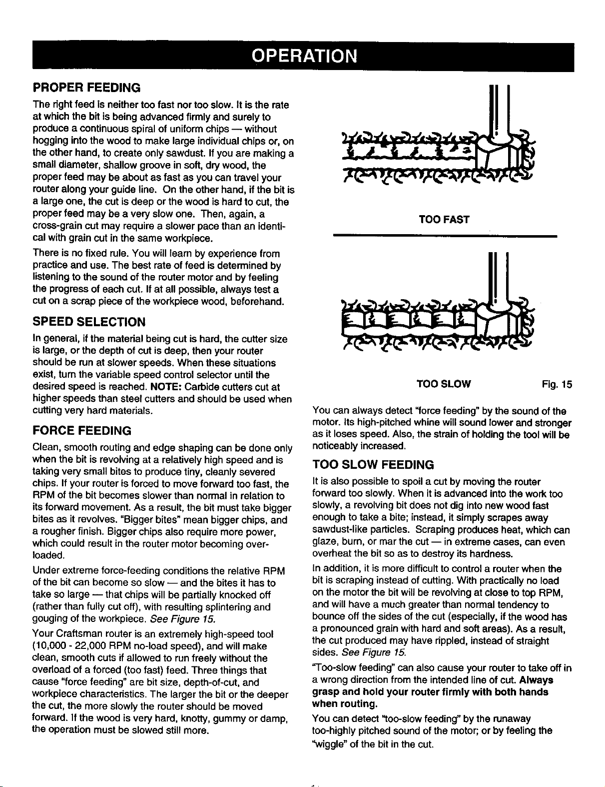
Under extreme force-feeding conditions the relative RPM
of the bit can become so slow -- and the bites it has to
take so large -- that chips will be partially knocked off
(rather than fully cut off), with resulting splintering and
gouging of the workpiece. See Figure 15.
Your Craftsman router is an extremely high-speed tool
(10,000 - 22,000 RPM no-load speed), and will make
clean, smooth cuts ifallowed to run freely without the
overload of a forced (too fast) feed. Three things that
cause "force feeding" are bit size, depth-of-cut, and
workpiece characteristics. The larger the bit or the deeper
the cut, the more slowly the router should be moved
forward. If the wood is very hard, knotty, gummy or damp,
the operation must be slowed still more.
TOO FAST
TOO SLOW Fig. 15
You can always detect "force feeding" by the sound of the
motor. Its high-pitched whine will sound lower and stronger
as it loses speed. Also, the strain of holdingthe tool will be
noticeably increased.
TOO SLOW FEEDING
It isalso possible to spoil a cut by moving the router
forward too slowly. When it is advanced into the work too
slowly, a revolving bit does not dig into new wood fast
enough to take a bite; instead, it simply scrapes away
sawdust-like particles. Scraping produces heat, which can
glaze, burn, or mar the cut -- in extreme cases, san even
overheat the bit so as to destroy its hardness.
In addition, it is more difficult to control a router when the
bit is scraping instead of cutting. With practically no load
on the motor the bit will be revolving at close to top RPM,
and will have a much greater than normal tendency to
bounce off the sides of the cut (especially, if the wood has
a pronounced grain with hard and soft areas). As a result,
the cut produced may have rippled, instead of straight
sides. See Figure 15.
"Too-slow feeding" can also cause your router to take off in
a wrong direction from the intended line of cut. Always
grasp and hold your router firmly with both hands
when routing.
You can detect "too-slow feeding" by the runaway
too-highly pitched sound ofthe motor; or by feeling the
"wiggle" of the bit in the cut.
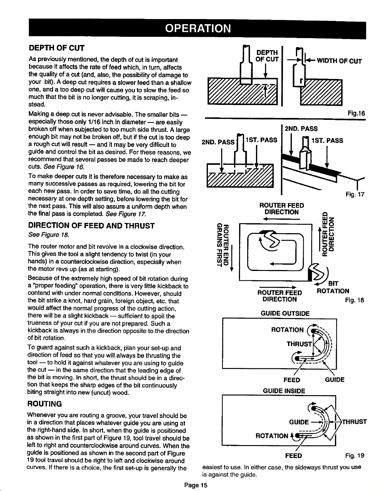
DEPTH OF CUT
As previously mentioned, the depth of cut is important
because it affects the rate of feed which, in tum, affects
the quality of a cut (and, also, the possibility of damage to
your bit). A deep cut requires a slower feed than a shallow
one, and a too deep cut will cause you to slowthe feed so
much that the bit is no longer cutting, itis scraping, in-
stead.
Making a deep cut is never advisable. The smaller bits --
especially those only 1116 inch in diameter -- are easily
broken offwhen subjected to too much side thrust. A large
enough bit may not be broken off, but ifthe cut is too deep
a rough cut will result -- and it may be very difficult to
guide and control the bit as desired. For these reasons, we
recommend that several passes be made to reach deeper
cuts. See Figure 16.
To make deeper cuts it is therefore necessary to make as
many successive passes as required, Iowedng the bit for
each new pass. In order to save time, do all the cutting
necessary at one depth setting, before Iowedng the bit for
the next pass. This will also assure a uniform depth when
the final pass is completed. See Figure 17.
DIRECTION OF FEED AND THRUST
See Figure 18.
DEPTH
OF CUT _'- WIDTH OF CUT
Fig.16
2ND. PASS
2ND. iASs_IS i PASS
Fig. 17
ROUTER FEED
The router motor and bit revolve in a clockwise direction.
This gives the tool a slighttendency to twist (in your
hands) ina counterclockwise direction, especially when
the motor revs up (as at starting).
Because of the extremely high speed of bit rotation dudng
a "proper feeding" operation, there isvery little kickback to
contend with under normal conditions. However, should
the bitstrike a knot, hard grain, foreign object, etc. that
would affect the normal progress of the cutting action,
there will be a slight kickback-- sufficientto spoil the
trueness of your cut ifyou are not prepared. Such a
kickback is always in the direction opposite to the direction
of bit rotation.
To guard against such a kickback, plan your set-up and
direction of feed so that you will always be thrusting the
tool -- to hold it against whatever you are using to guide
the cut- in the same direction that the leading edge of
the bit is moving. In short, the thrust should be in a direc-
tion that keeps the sharp edges of the bitcontinuously
biting straight into new (uncut) wood.
ROUTING
Whenever you are routing a groove, your travel should be
in a directionthat places whatever guide you are using at
the right-hand side. In short, when the guide is positioned
as shown in the first part of Figure 19, tool travel should be
left to right and counterclockwise around curves. When the
guide is positioned as shown in the second part of Figure
19 tool travel should be dght to left and clockwise around
curves. If there is a choice, the first set-up is generally the
ROUTER FEED ROTATION
D
DIRECTION Fig. 18
GUIDE OUTSIDE
ROTATION _
THRUST_ )
FEED GUIDE
GUIDE INSIDE
ROTATION __
/
FEED
easiest to use. In either case, the sideways thrust you use
is against the guide.
Page 15
THRUST
Fig. 19
EDGEROUTING
Race muter on workpiece, making sure the muter bit does
not contact workpiece. Turn muter on and let motor build to
its full speed. Begin your cut, gradually feeding cutter into
workpiece.
A
Upon completion of cut, turn motor off and let it come to a
complete stop before removing router from work surface.
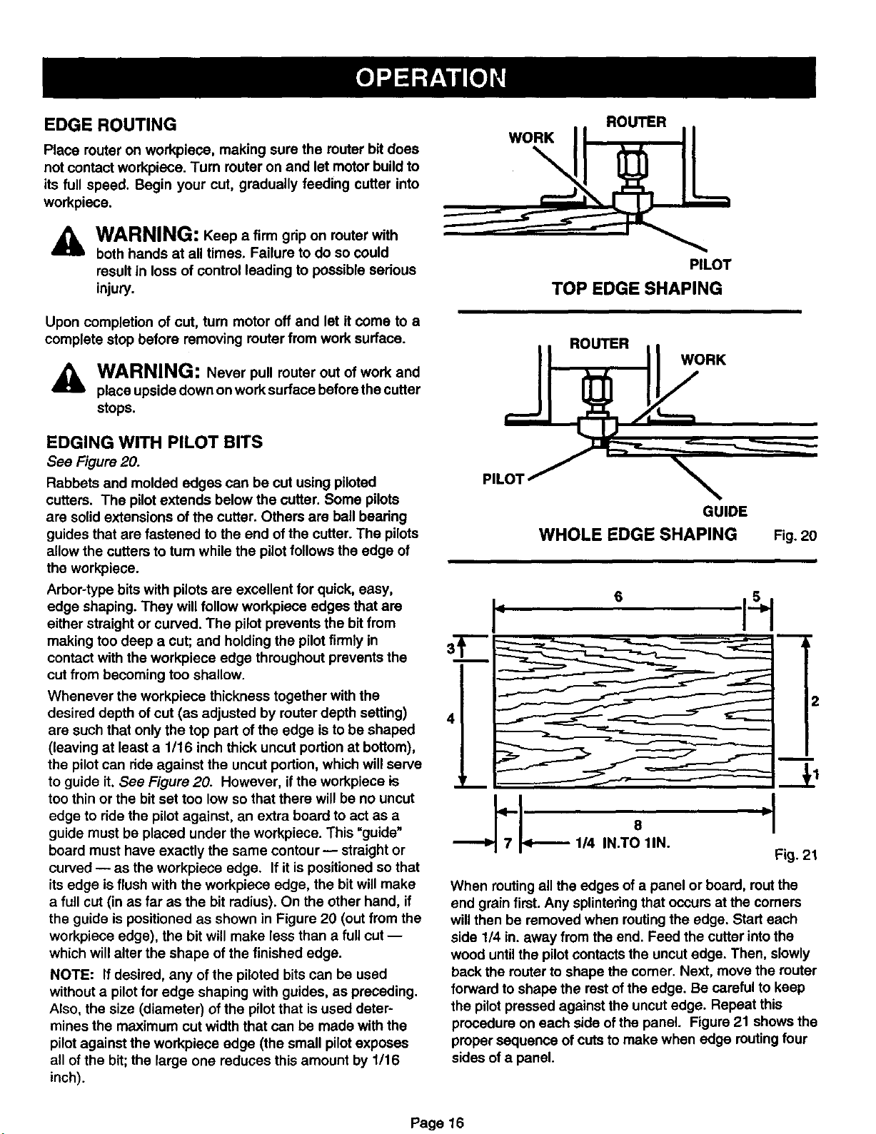
EDGING WITH PILOT BITS
See Figure 20.
Rabbets and molded edges can be cut using piloted
cutters. The pilotextends below the cutter. Some pilots
are solid extensions of the cutter. Others are ball beadng
guides that are fastened to the end ofthe cutter. The pilots
allow the cutters to tum while the pilot follows the edge of
the workpiece.
Arbor-type bits with pilotsare excellent for quick, easy,
edge shaping. They will follow workpiece edges that are
either straight or curved. The pilot prevents the bit from
making toodeep a cut; and holding the pilot firmly in
contact with the workpiece edge throughout prevents the
cut from becoming too shallow.
Whenever the workpiece thickness together with the
desired depth of cut (as adjusted by router depth setting)
are such that only the top part of the edge is to be shaped
(leaving at least a 1/16 inch thick uncut portion at bottom),
the pilotcan dde against the uncut portion, which will serve
to guide it. See Figure 20. However, if the workpiece is
too thin or the bit set too low so that there will be no uncut
edge to ride the pilot against, an extra board to act as a
guide must be placed under the workpiece. This "guide"
board must have exactly the same contour -- straight or
curved -- as the workpiece edge. If it is positioned so that
its edge is flush with the workpiece edge, the bit will make
a full cut (in as far as the bit radius). On the other hand, if
the guide is positioned as shown in Figure 20 (out from the
workpiece edge), the bit will make less than a full cut --
which will alter the shape of the finished edge.
NOTE: If desired, any of the piloted bits can be used
without a pilot for edge shaping with guides, as preceding.
Also, the size (diameter) of the pilot that is used deter-
mines the maximum cut width that can be made with the
pilot against the workpiece edge (the small pilot exposes
all of the bit; the large one reduces this amount by 1/16
inch).
WARNING: Keep a firm grip on router with
both hands at all times. Failure to do so could
result inloss of control leading to possible serious
injury.
WARNING: Never pull router out of work and
place upside down on work surface beforethe cutter
stops.
PILOT
TOP EDGE SHAPING
ROUTER
WORK
GUIDE
WHOLE EDGE SHAPING
,. °
I-
Fig. 20
"m'l
6 rl
1/4 IN.TO 1IN.
When routing all the edges of a panel or board, rout the
end grain first. Any splintedngthat occurs at the comers
will then be removed when routing the edge. Start each
side 1/4 in. away from the end. Feed the cutterinto the
wood untilthe pilotcontacts the uncut edge. Then, slowly
back the router to shape the comer. Next, move the router
forward toshape the restof the edge. Be careful to keep
the pilotpressed against the uncut edge. Repeat this
procedure on each side ofthe panel. Figure 21 shows the
proper sequence of cuts to make when edge muting four
sides of a panel.
Fig. 21
Page 16
 Loading...