

Craftsman 31525790 Owner’s Manual
OWNERS
MANUAL
MODEL NO.
315.25790
CAUTION:
Read Rules for
Safe Operation
and Instructions
Carefully
_ __....._i! ¸ .......
..... _,_
i
}
:!
i:_:i!:ii:i_i_iiiiil
TEMPLATE
FOR USE WITH ALL CRAFTSMAN ROUTERS
SAVE THIS
MANUAL FOR
FUTURE REFERENCE
SEARS, ROEBUCK AND CO., Hoffman Estates, IL 60179
612647-176 Pa_NT_DI._SA
5"93
Operation
Repair Parts
Sold only by
Introduction
RULES FOR SAFE OPERATION
DaSCONNECT TOOLS. When not in use, before assembling, before servicing, or
when changing attachments, blades, bits, cutters, etc,, all tools shoutd be discon-
nected.
2.
BE SURE ALL ADJUSTMENTS ARE PROPERLY SET AND SECURELY FASTENED.
3.
KEEP GUARDS IN PLACE and in working order.
4.
KEEP WORK AREA CLEAN. Cluttered areas and benches invite accidents.
5.
AVOID DANGEROUS ENVIRONMENT. Don't use power tool in damp or wet Iooa-
tions or expose to rain. Keep work area we!l tit.
6.
KEEP CHILDREN AWAY. Atl visitors should wear safety glasses and be kept a safe
distance from work area. Do not let visitors contact tool or extension cord.
7.
STORE iDLE TOOLS. When not in use, tools should be stored in a dry, high or
locked-up place -- out of the reach of children.
8.
WEAR PROPER APPAREL, No loose clothing or jewelry to get caught in moving
parts. Rubber gloves and footwear are recommended when working outdoors, Also,
wear protective hair covering to contain long hair.
9.
USE SAFETY GLASSES with all tools, Also face or dust mask if operation is dusty.
10.
SECURE WORK. Use clamps or a vise to hold work, It's safer than using your hand
and it frees both hands to operate tool.
11.
DON'T OVERREACH. Keep proper footing and balance at all times. Do not use on a
ladder or unstable support.
12.
NEVER USE iN AN EXPLOS0VE ATMOSPHERE. Normal sparking of the motor could
ignite fumes.
13.
KEEP TEMPLATE DRY, CLEAN, AND FREE FROM OIL AND GREASE,
14.
STAY ALERT, Watch what you are doing and use common sense. Do not operate
tool when you are tired, Do not rush.
15.
DRUGS, ALCOHOL, MEDICATION. Do not operate tool while under the influence of
drugs, alcohol, or any medication.
16.
CHECK FREQUENTLY DURING OPERATmON TO INSURE REQUIRED POSIT_ON
AND TO PREVENT HOLDING MECHANISM FROM BECOMING LOOSENED.
17.
SECURE Dovetail Template to a workbench. See Figures 5 & 6, Page 4.
18,
SAVE THESE mNSTRUCT]ONS.
The operation of any Power Tool con result in tereign objects being thrown into your
eyes which can result in severe eye damage, Before cornmeneirmg power tool opera-
tion, always wear safety goggles or safety glasses with side shields and a full face
shield when needed. We recommend Wide Vision Salary Mask for use over
eyeglasses or standard safety glasses with side shields, available at Sears Catalog
Order or Retail Stores,
Page 2
INTRODUCTION
ASSEMBLY
Unpack your dovetail template, separating and
removing all loose parts from the packaging
materials. Check each item with the "Table of Loose
Parts" to make sure all items listed have been pack
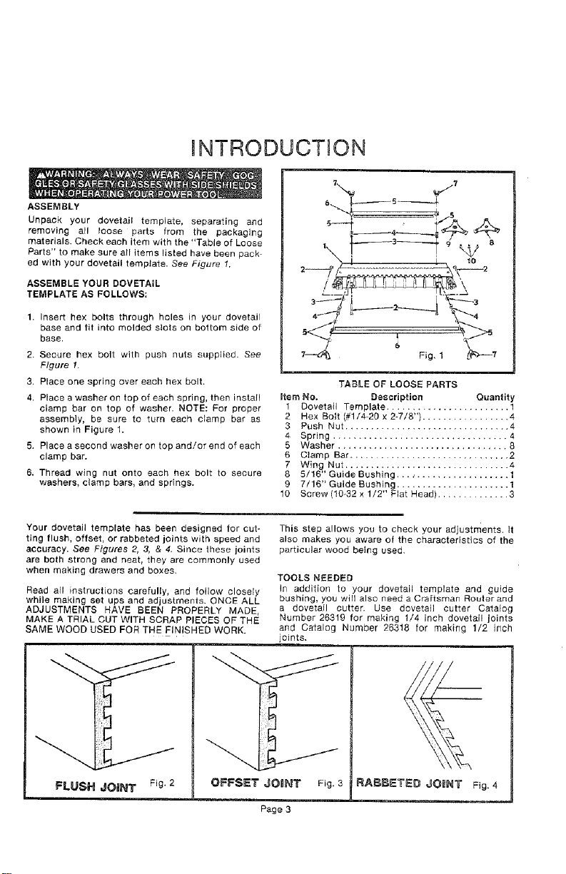
ed with your dovetail template. See Figure 1.
ASSEMBLE YOUR DOVETAIL
TEMPLATE AS FOLLOWS:
1. Insert hex bolts through holes in your dovetail
base and tit into molded slots on bottom side of
base.
2. Secure hex bolt with push nuts supplied. See
Figure 1.
3. Place one spring over each hex bolt.
4. Place a washer on top of each spring, then install
clamp bar on top of washer. NOTE: For proper
assembly, be sure to turn each clamp bar as
shown in Figure 1.
5. Place a second washer on top and/or end of each
clamp bar.
6. Thread wing nut onto each hex bolt to secure
washers, clamp bars, and springs.
Item No.
1
2
3
4
5
6
7
8
9
10
TABLE OF LOOSE PARTS
Dovetail Template ........................ 1
Hex Bolt (#1/4-20 x 2-7/8") ................. 4
Push Nut ................................ 4
Spring .................................. 4
Washer ................................. 8
Clamp Bar ............................. 2
Wing Nut ................................
5/16" Guide Bushing...., .................. 1
7/16" Guide Bushing ...................... 1
Screw (10o32 x 1/2" Flat Head) .............. 3
Description Quantity
Your dovetail template has been designed for cut-
ting flush, offset, or rabbeted joints with speed and
accuracy. See Figures 2, 3, & 4. Since these joints
are both strong and neat, they are commonly used
when making drawers and boxes.
Read atl instructions carefully, and follow closely
while making set ups and adjustments. ONCE ALL
ADJUSTMENTS HAVE BEEN PROPERLY MADE,
MAKE A TRIAL CUT WITH SCRAP PIECES OF THE
SAME WOOD USED FOR THE FINISHED WORK.
FLUSH JOINT Fig. 2 OFFSET JOnNT
This step allows you to check your adjustments, it
also makes you aware of the characteristics of the
particular wood being used,
TOOLS NEEDED
In addition to your dovetail template and guide
bushing, you will also need a Craftsman Rouler and
a dovetail cutter. Use dovetail cutter Catalog
Number 26319 for making 1/4 inch dovetail joints
and Catalog Number 26318 for making 1/2 inch
joints.
Fig, 3
Page 3
OPERATION
MOUNTING DOVETAIL TEMPLATE
FOR SAFE OPERATION AND PROPER CONTROL,
YOUR DOVETAIL TEMPLATE MUST BE MOUNTED
TO A WORKBENCH OR TABLE. If desired, it can be
clamped to a workbench with "C" clamps, or it can
be mounted onto a 3/4 inch piece of plywood for
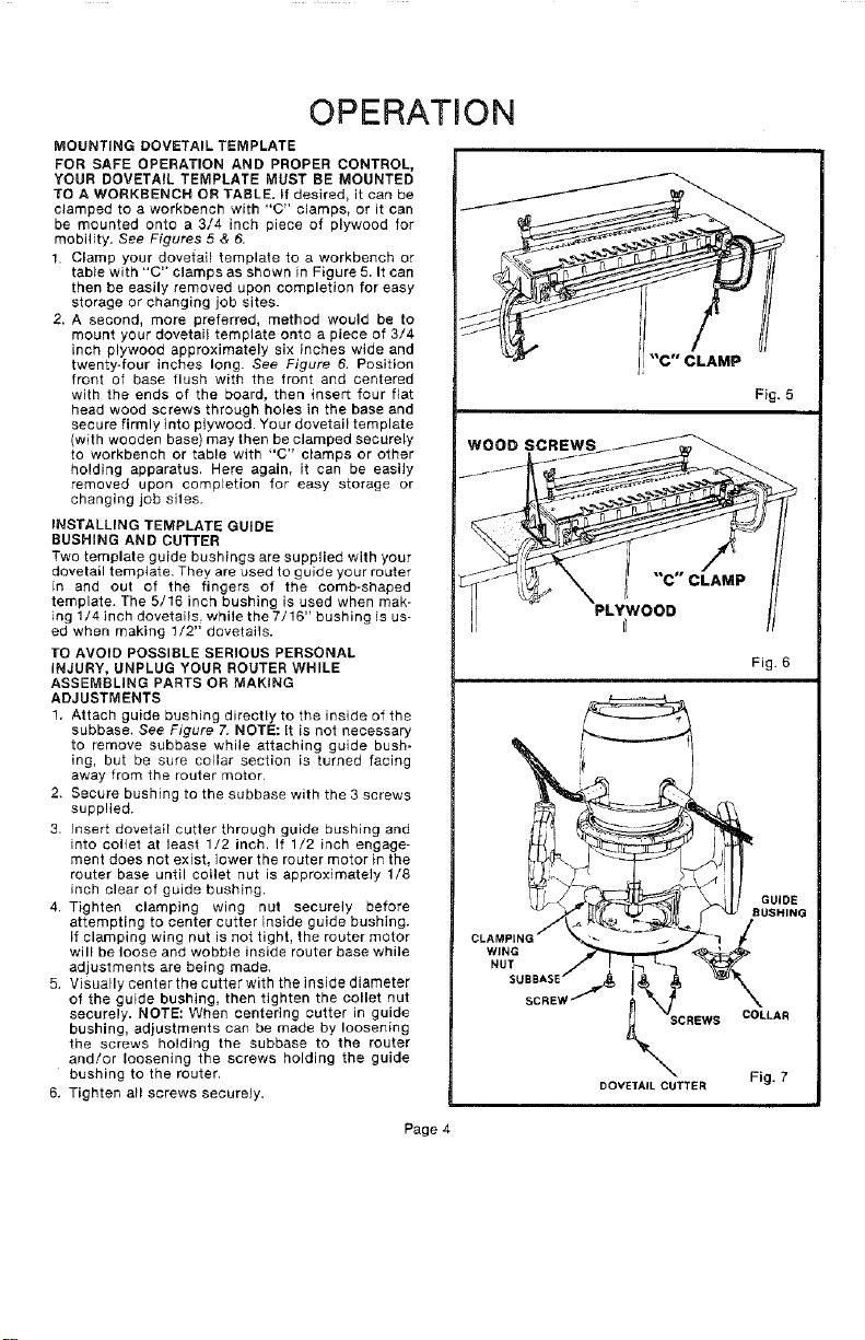
mobility. See Figures 5 & 6.
1. Clamp your dovetail template to a workbench or
tab}e with "C" clamps as shown in Figure 5. It can
then be easily removed upon completion for easy
storage or changing job sites.
2. A second, more preferred, method would be to
mount your dovetai_ template onto a piece of 3/4
inch plywood approximately six inches wide and
twenty-four inches long. See Figure 6. Position
front of base flush with the front and centered
with the ends of the board, then insert four fiat
head wood screws through holes in the base and
secure firmly into plywood. Your dovetail template
(with wooden base) may then be clamped securely
to workbench or table with "C" clamps or other
holding apparatus. Here again, it can be easily
removed upon completion for easy storage or
changing job sites.
INSTALLING TEMPLATE GUIDE
RUSHING AND CUTTER
Two template guide bushings are supplied with your
dovetail template. They are used to guide your router
in and out of the fingers of the comb-shaped
template. The 5/16 inch bushing is used when mak-
ing 1/4 inch dovetails, while the 7/16" bushing is us-
ed when making 1/2" dovetails.
1"O AVOID POSSIBLE SERIOUS PERSONAL
INJURY, UNPLUG YOUR ROUTER WHILE
ASSEMBLING PARTS OR MAKING
ADJUSTMENTS
1. Attach guide bushing directly to the inside of the
subbase, See Figure 7. NOTE: It is not necessary
to remove subbase while attaching guide bush-
ing, but be sure collar section is turned facing
away from the router motor.
2. Secure bushing to the subbase with the 3 screws
supplied.
3. Insert dovetail cutter through guide bushing and
into collet at least 1/2 inch, If 1/2 inch engage-
ment does not exist, lower the router motor in the
router base until collet nut is approximately 1/8
inch clear of guide bushing.
4. Tighten clamping wing nut securely before
attempting to center cutter inside guide bushing.
If clamping wing nut is not tighL the router motor
will be loose and wobble inside router base while
adjustments are being made.
5. Visually center the cutter with the inside diameter
of the guide bushing, then tighten the collet nut
securely. NOTE: When centering cutter in guide
bushing, adjustments can be made by loosening
the screws holding the subbase to the router
and!or loosening the screws holding the guide
bushing to the router.
6, Tighten all screws securely.
Page 4
WOOD SCREWS
Fig. 5
"C" CLAMP
PLYWOOD
r_
Fig. 6
SCREWS COLLAR
DOVEfAIL CUTTER Fig. 7
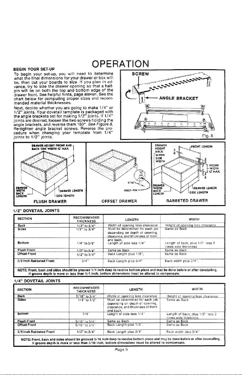
BEGIN YOUR SET-UP
To begin your set-up, you will need to determine
what the final dimensions for your drawer or box will
be, then cut your boards to size. if you plan in ad
vance, try to size the drawer opening so that a half-
pin will be on both the top and bottom edge of the
drawer front. See helpful hints, page eleven. See the
chart below for computing proper sizes and recom-
mended material thicknesses.
Next, decide whether you are going to make 1/4" or
1/2" joints. Your dovetail template is packaged with
the angle brackets set for making 1/2" joints. If 1/4"
joints are desired, loosen the two screws holding the
angle brackets, and reverse them 180 ° . See Figure 8.
Re-tighten angle bracket screws. Reverse the pro
cedure when changing your template from 1/4"
joints to 1/2" joints.
OPERATION
SCREW
L£NGTH LSIDE LENGTH
FLUSH DRAWER
OFFSET DRAWER
RABBETED DRAWER
LENGTH
/2" DOVETAIL JOINTS
SECTION
Back
Sides
Bottom
Flush Front
Offset.Front
3/8Inch Rabbeted Front
NOTE: Pronl, back and sides should be grooved 1/4 inch deep to receive bottom piece and may be done belore or after dovetailing,
If groove depth is mo_e or less than 1/4 inch, bottom dimensions must be altered to compensate.
RECOMMENDED
THICKNESS
/2" t9 _/4"
1/2" to 3/4"
1/4"to 3/8"
1/?"in 314""
1/2"to 3/4"
3/4"
LENGTH WIDTH
Width of openin_ less clearance He!ght of openinc] less clearance
Must be determined, for each io_3 _ Same as Back
depending on depth of opening,
clearance, and thickness of fron[_._ ......
and back.
Length of side less 1/4" Length of back, plus 1/2 less 2
S_me as Back Same as Back
Back Length plus 1/8", Same as Back
Length plus
Back 3/4" Back width plus 3/4'
times side thickness
1/4" DOVETAIL JOINTS
SECTION
Back
Sides
Bottom
Fl_sh Front
Offset.Front
3/8 Inch Rabbeted Front
NOTE: Front, back and sides should be grooved 3/16 inch deep to receive bottom piece and may be done before or Mter dovetaging,
R groove depth is more or less than 3/16 inch, bottom dimensions must be altered to compensale.
RECOMMENDED
THICKNESS
5/t6" to $/4'
1/4" to 1/2"
1/4"
5/16"to 3/4"
1/2"to 3/4"
LENGTH
Width of opening less c ea,ance
Must be determined for each lob
depending on deptB of opening,
c_e_,ran_e, and thickness Of front
and b6g_
Lenglh of side less 1/4'
Same as Back
Back Length plus 1/8',
Back Lenglh plus 3/4"
Page 5
Heiqht of openinq le_ea_arlcL
Same as Back
Length of back, ulus 1/2" ess 2
times side thickness
Same as Back
Same as B_ck
Back width olus 3/4"
WIDTH
 Loading...