

Craftsman 315248200 Owner’s Manual
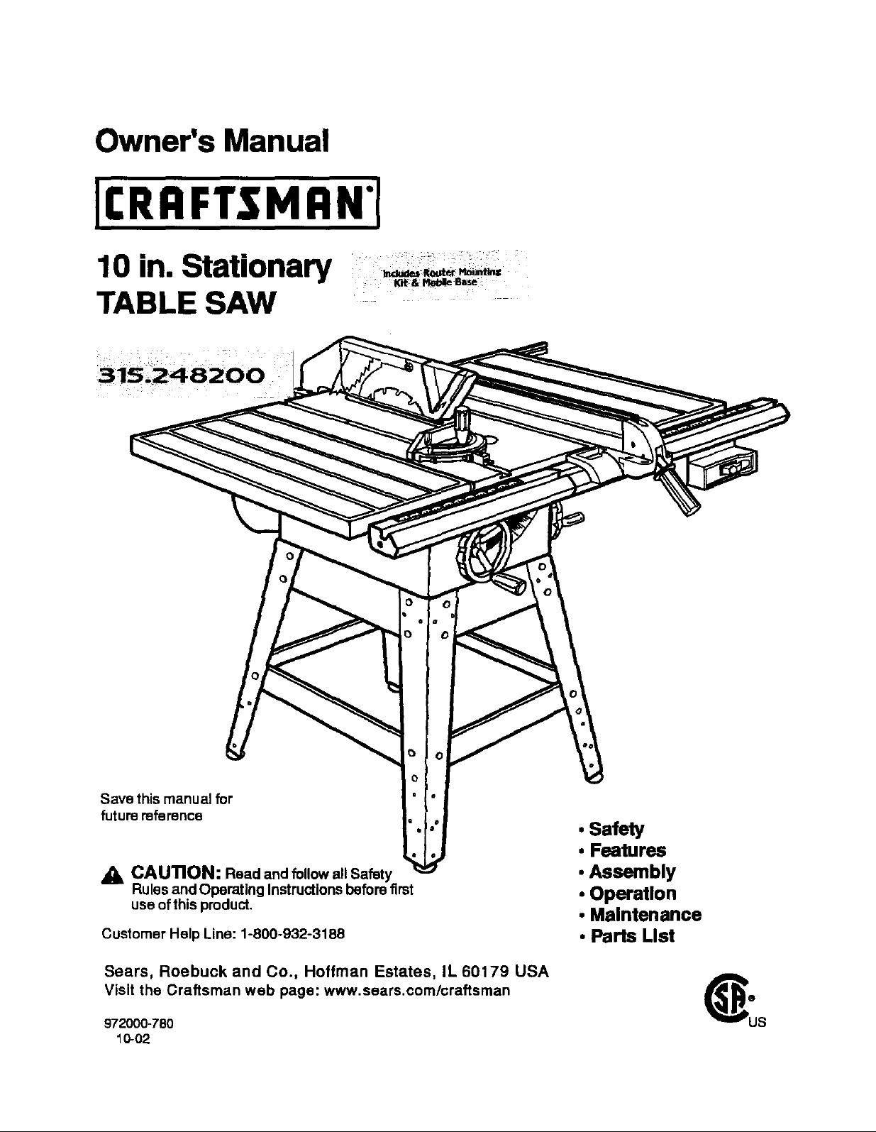
Owner's Manual
10 in. Stationary
TABLE SAW
O
Save this manual for
future reference
CAUTION: Read and follow all Safety
Rules and Operating Instructions before first
use of this product.
Customer Help Line: 1-800-932-3188
Sears, Roebuck and Co., Hoffman Estates, IL 60179 USA
Visit the Craftsman web page: www.sears.com/craftsman
972000-780
10-02
• Safety
• Features
• Assembly
• Operation
• Maintenance
• Parts List
FULL ONE YEAR WARRANTY ON CRAFTSMAN TABLE SAW
If this(RAFTSMAN Table Saw fails due to a defeat in matedal or workmanshipwithin one year from the date
of pumhase, Sears will repair it, free of charge.
Contacta Sears Service Canter for repair.
if this productis used for commercial or rental purposes,this warranty applies onlyfor 90 days from the date
ofpurchase.
Thiswarrantygivesyou specificlegalrights,and you may alsohaveotherdghtswhichvaryfromstateto
state.
Seare, Roebuck and Co., Dept. 8t7WA, Hoffman Estate,=,IL 60179
Yoursaw has manyfeatures for making cuttingoperations more pleasantend enjoyable. Safety, performance
and dependabilityhave been giventop priorityinthe designof this saw makingiteasy to maintainand operate,
CAUTION: Carefully read throughthisentire owner'smanual before usingyour new saw. Pay close
attentiontothe Rules ForSafe Operation, and all Safety Alert Symbols,includingDanger, Warning and
Caution. If you use yoursaw propedyand onlyfor what itis intended,youwill enjoyyears of safe, reliable
service.
,_, Lookfor this symbol to point out important safetyprecautions,It means attention!!!Yoursafety is involved.
• k WARNING:
The operation of any powertool san resultin foreign objectsbeing thrown into your eyes,
whichcan result in severe eye damage, Before beginningpower tool operation, always
wear safety goggles or safetyglasseswith side shieldsand a fullface shieldwhen needed.
We recommend a WideVision Safety Maskfor usa over eyeglasses or standardsafety
glasses with side shields,availableat Sears Retail Stores.
• Warranty and Introduction............................................................................................................................. 2
• Table Of Contents ...................................................................................................................................... 2-3
• Rules ForSafe Operation........................................................................................................................... 4-6
• Electrical ....................................................................................................................................................... 7
• Glossary and ProductSpecifications............................................................................................................ 8
• Unpacking and Accassodes ......................................................................................................................... 9
• Loose Parts List.......................................................................................................................................... 10
• Small Parts List...................................................................................................................................... 11-12
• Tools Needed .............................................................................................................................................. 13
• Labels ..................................................................................................................................................... 14-15
• Features ................................................................................................................................................. 16-17
• Assembly................................................................................................................................................ 16-29
InstallingHandwheals on Table Sew Base ................................................................................................. 18
AssemblingLeg Stand ........................................................................................................................... 16-19
CRAFTSMAN"TABLESAW315.228390 2

MountingtheLegStandontheTableSawBase........................................................................................ 19
AssemblingTable Extensions..................................................................................................................... 20
AligningTable Extensions ..................................................................................................... 20
Installingthe Rear Rail................................................................................................................................ 21
Installingthe Front Rail ............................................................................................................................... 22
Aligning Rip Fence and Rails ...................................................................................................................... 23
Mountingthe Motor...................................................................................................................................... 23
Installing the Belt and Belt Guard ............................................................................................................... 24
Checkingthe Throat Plate........................................................................................................................... 24
Installingthe BladeGuard ........................................................................................................................... 25
Aligning the RivingKnife withthe Blade ..................................................................................................... 26
Check Heeling (Paralleling)of the Saw Bladeto the Miter Gage Groove .................................................. 27
Checking RipFence and BladeAlignment .................................................................................................. 28
CheckingSquareness of ExtensionTables to Saw Table .......................................................................... 29
• Adjustments............................................................................................................................................ 30-34
Replacingthe Blade .................................................................................................................................... 30
Heeling (Paralleling)the Sawblade to Miter Gage Groove.................................................................... 31-32
Settingthe Bevel Stopsand Indicator.................................................................................................... 32-33
Adjustingthe Miter Gage ............................................................................................................................. 33
Removing/ Replacing the Throat Plate ...................................................................................................... 34
• BasicOperation of the Table Saw ......................................................................................................... 35-42
Causes of Kickback .................................................................................................................................... 35
Avoiding Kickback....................................................................................................................................... 35
CuttingAids................................................................................................................................................. 35
Types of Cuts .............................................................................................................................................. 36
Making a Cross Cut..................................................................................................................................... 37
Making a Rip Cut .................................................................................................................................... 37-38
Making a Miter Cut ...................................................................................................................................... 38
Making a Bevel Cross Cut ..................................................................................................................... 38-39
Making a Bevel Rip Cut ............................................................................................................................... 39
Making a Compound (Bevel) Miter Cut....................................................................................................... 40
Making a Large Panel Cut ........................................................................................................................... 41
Makinga Non-ThroughCUt ......................................................................................................................... 41
Makinga Dado Cut ...................................................................................................................................... 42
• Maintenance ................................................................................................................................................ 43
• Lubrication................................................................................................................................................... 43
• Troubleshooting...................................................................................................................................... 44.46
• ExplodedView and Repair Parts List..................................................................................................... 48-65
• Parts Ordering/ Sen/ica ................................................................................................................ back page
3 cnn_lrxHnr TABLESAW31,5,228390
The purposeof safety symbols isto attractyour attentionto possibledangers. The safety symbols,and the
explanationswiththem, deserve your careful attentionand understanding,The safety warnings do not by
themselves eliminateany danger. The instructionsorwarningsthey give are notsubstitutesfor proper accident
preventionmeasures.
SYMBOL MEANING
&
SAFETY ALERT SYMBOL
Indicates danger, warning,or caution. May be used in conjunctionwithother symbolsor
pictugraphs.
&
A
&
Note: Advisesyou of informationorInstructions vital to the operationor maintenanceofthe equipment,
IMPORTANT
Servicingrequiresextreme care and knowledgeofthe
system and should be performed onlybya qualified
servicetechnician, For servicewe suggestyou return
the toolto yournearest Sears store or repaircenter.
Alwaysuse odginalfactory replacement partswhen
servicing.
READ ALL INSTRUCTIONS
• KNOW YOUR POWER TOOL. Read the owner's
manual carefully, Leam the saw's applications
and limitationsas well as the specific potential
hazards related to this tool.
• DO NOT USE IN DANGEROUS ENVIRON-
MENT. Do not use power tools near gasoline or
other flammable liquids,in damp or wet loca-
tions, or expose them to rain. Keep the work
area well lit.
• MAKE WORKSHOP CHILD-PROOF with
padlocks and master switchesor by removing
starter keys.
• KEEP CHILDREN AND VISITORS AWAY. All
visitors sbou|dwear safety glasses and be kept
a safe distance from work area. Do not let
visitorscontact tool or extension cordwhile
operating.
• KEEP THE WORK AREA CLEAN. Cluttered
work areas and work benches inviteaccidents.
DO NOT leave toolsor pieces of wood on the
saw while it is in operation,
DANG ER: Failureto obey a safety warningwill result inseriousinjuryto yourselfor toothers,
Always followthe safety precautionsto reducethe riskof fire, electdc shockand personalinjuP/,
WARNING: Failureto obey a safety warningcan resultin sadous Injury to yourselfor to others,
Always followthe safetyprecautionsto reducethe riskof fire, electdc shockand personal injuw.
CAUTION: Failureto obey a safety warning may resultin propertydamage or personal injulyto
yourselforto others.Alwaysfollow the safety precautionsto reduce the dsk of fire,electricshock
and personal injury,
_, WARNING: Do not attemptto operate thistool
untilyou have read thoroughlyand understand
completelyall instructions,safetyrules,etc.
containedinthis manual. Failure to complycan
resultin accidentsinvolvingfire, electrical shock,
or serious personal injury.Save theowners
manualand reviewfrequentlyfor continuingsafe
operation,and instructingotherswho rneyusa
this tool.
• MAINTAIN TOOLS WITH CARE. Keeptools
sharpand clean for better and safer perfor-
mance. Follow instructionsfor lubricatingand
changing accessories,
• USE THE RIGHT TOOL FOR THE JOB. Do not
force the toolor attachmentto do a job it was
not designedfor. Usa it onlythe way it was
intended.
• DRESS PROPERLY. Do not wear loose cloth-
ing. gloves, neckties, rings, bracelets, or other
jewelry. They can get caught and draw you into
moving parts. Rubber gloves and nonslip
footwear are recommended.Also wear protec-
tive hair covedng to contain long hair.
• ALWAYS WEAR SAFETY GLASSES WITH
SIDE SHIELDS. Everyday eyeglasses have only
impact-rasistantlenses; they are NOT safety
glaseas.
• NEVER STAND ON TOOL, Serious injurycould
or.curifthe tool is tipped or if the blade is
unintentionallycontacted.
EIIRFTIMRIr TABLESAW315.228390 4
RULES FOR SAFE OPERATION (Continued)
• DO NOT OVERREACH. Keep properfootingand
balance at all times.
• SECURE WORK. Usa clamps or • vise to hold
work when practical. It's safer then usingyour
handand frees bothhandsto operate tool.
• USE THE PROPER EXTENSION CORD. Make
sure your extension cord is in good condition,
Use only a cord heavy enoughto carry the
currentyour product will drew,An undersized
cordwillcause a drop in linevoltage resultingin
loss of powerand overheating.A wire gage size
(A.W,G.) ofat least 14 is recommendedfor an
extension cord 25 feat or less in length. If in
doubt, usethe next heavier gage. The smaller
the gage number, the heavierthe cord.
• AVOID ACCIDENTAL STARTING. Be sure
switchis off when pluggingin,
• REMOVE WRENCHES AND ADJUSTING
KEYS, Get in the habit of checking- before
turning on tool - that hex keys and adjusting
wrenches are removedfrom tool.
CHECK DAMAGED PARTS. Beforeusingthe
tool again, check any damaged parts, including
guards,for proper operation and perfon_anca.
Check alignment of movingparts, bindingof
moving parts, breakage of parts, saw stability,
mountingand any other conditionsthat may
affect its operation. A damaged part muStbe
proparlyrepaired or replaced bya qualified
service technician at a Sears Store or repair
center to avoid riskof personalinjury.
USE ONLY CORRECT BLADES. Use the dght
blade size, style and cuttingspeed for the
matedal and the type of cut. Bladeteeth should
point downtoward the frontofthe table.
• USE RECOMMENDED ACCESSORIES. Using
improper accessories may risk injury.
USE ONLY SEARS REPLACEMENT PARTS.
All repairs, whether electrical or mechanical,
shouldbe made by a qualified sarvice technician
at a Sears Store or repair center.
• KEEP GUARDS IN PLACE and in goodworking
order, This includesthe bladeguard, dying
knife, and anti-ldckback pawls.
• CHECK DIRECTION OF FEED. Feed work into
a blade orcutter against the direction of rotation
of the blade or cutter only.
DISCONNECT ALL TOOLS. When notin use,
before saP.'icing, or when changing attachments,
blades, bits,cutters, etc., all tools should be
disconnectedfrom power supply.
• DO NOT FORCE THE TOOL. Itwill dothe job
better and more safely at the rate for which it
was designed,
• NEVER LEAVE TOOL RUNNING UNAT-
TENDED. TURN THE POWER OFF. Do not
leave tool until it comes to a complete Stop.
• BEFORE MOUNTING, DISCONNECTING OR
REMOUNTING THE MOTOR; unplugthe saw
and removethe switchkey.
A WARNING: When servicing,use only identical
Creflsman replacement parts. Use of any other
parts may create a hazard or cause product
damage.
• NEVER USE THIS TOOL IN AN EXPLOSNE
ATMOSPHERE. Normal sparkingofthe motor
could ignite fumes,
• MAKE SURE THE WORK AREA HAS AMPLE
LIGHTING to see the work and that no obStruc-
tions willinterferewith safe operation BEFORE
performingany work usingthis tool.
• DO NOT USE TOOL IF SWITCH DOES NOT
TURN n" ON AND OFF. Have defective
switches replaced by a qualified servicetechni-
cian at a Sears Store or repair center.
• GUARD AGAINST ELECTRICAL SHOCK by
preventingbodycontactwith grounded surfaces
such as pipes, radiators, ranges, refrigerator
enclosures.
• GROUND ALL TOOLS. See Electrical page.
• WEAR A DUST •ASK to keep from inhaling
fine particles.
• PROTECT YOUR HEARING. Wear hsaring
protectiondudngextended periodsof operation,
• DO NOT OPERATE THIS TOOL WHILE UN-
DER THE INFLUENCE OF DRUGS, ALCOHOL,
OR ANY MEDICATION.
• STAY ALERT AND EXERCISE CONTROL.
Watch whatyou ere doingand usecommon
sense. Do not operate tool when you are
tired. Do not rash.
• AVOID AWKWARD OPERATIONS AND HAND
PosmoNs where a sudden slipcouldcause
your handto move intothe blade. ALWAYS
make sure you have good balance.
• ALWAYS SUPPORT LARGE WORK PIECES
while cuttingto minimizerisk of blade pinching
and kickback.Saw may slip. walk or slide while
cutting large or heavy boards.
• GUARD AGAINST KICKBACK, Kickbackcan
occurwhen the blade stalls, drivingthe work
piece beck towardthe operator. It can pullyour
hand intothe blade, resultingin sedous personal
injury.Stay out ofthe blade path and turnswitch
off immediatelyif blade bindsor stalls.
5 I;IIIIFI'ZNRN" TABLESAW315.228390
RULES FOR SAFE OPERATION (Continued)
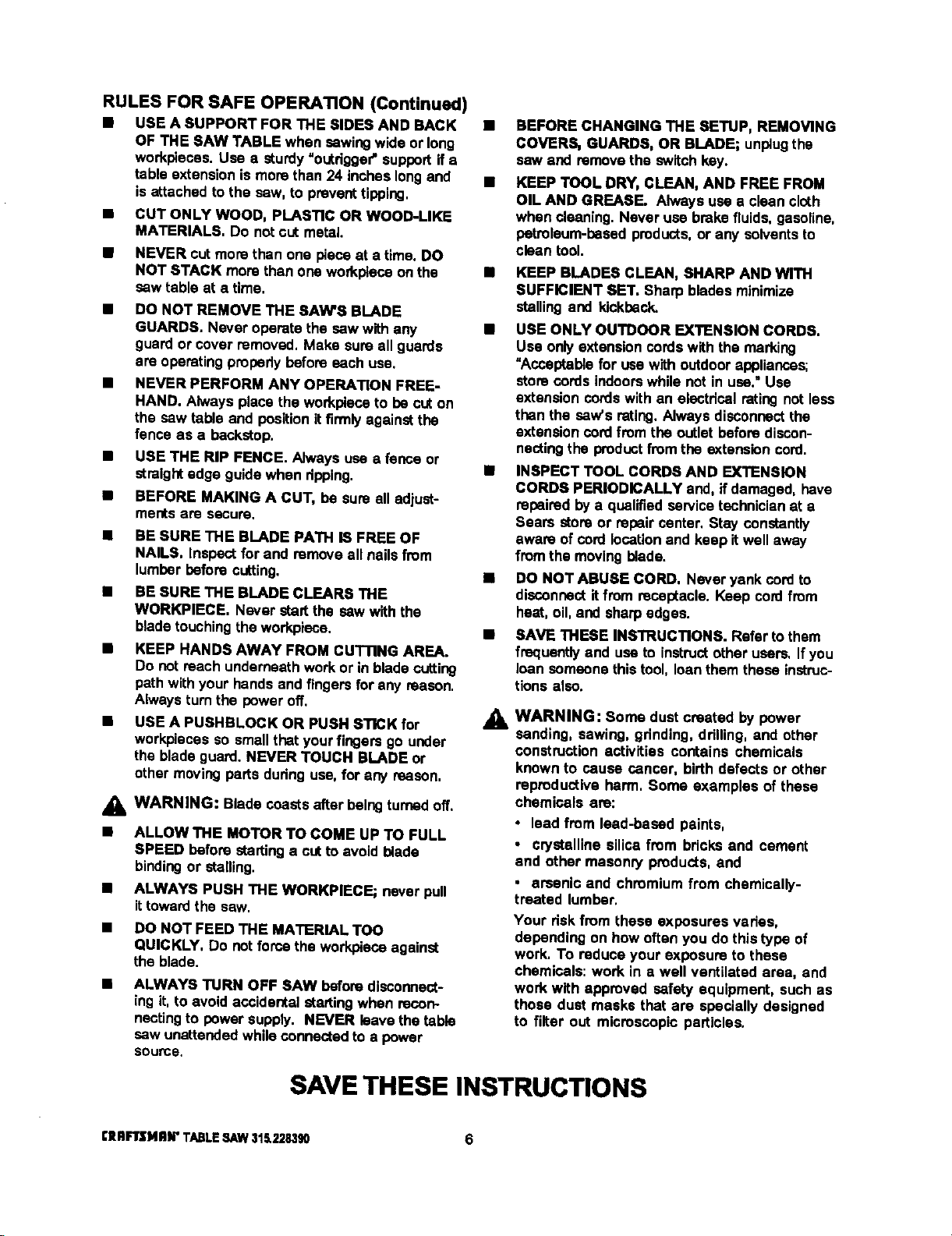
• USE A SUPPORT FOR THE SIDES AND BACK •
OF THE SAW TABLE when sawingwide or long
workpleoas. Usa e sturdy "outrigger"support if e
table extensionis more than 24 inches longand •
isattached to the saw, to prevent tipping,
CUT ONLY WOOD, PLASTIC OR WOOD-LIKE
MATERIALS. Do not cut metal.
NEVER cut more then one piece at a time. DO
NOT STACK more than one workpieceon the
saw table at a time,
DO NOT REMOVE THE SAW'S BLADE
GUARDS. Never operate the saw with any
guard or cover removed, Make sureall guards
are operating propedybefore each use,
NEVER PERFORM ANY OPERATION FREE-
HAND. Alwaysplace the workplaceto be cut on
the saw table and positionitfirmlyagainstthe
fence as a backstop.
USE THE RIP FENCE. Always usa a fence or
straight edge guide when ripping,
BEFORE MAKING A CUT, be sure all adjust-
ments are secure.
BE SURE THE BLADE PATH • FREE OF
NAILS. Inspect for and remove all nailsfrom
lumber before cutting.
• BE SURE THE BLADE CLEARS THE
WORKPIECE, Never start the saw with the
blade touching the workplace,
• KEEP HANDS AWAY FRO• CUTTING AREA.
Do not reach underneath work or in blade cutting
path withyour hands and fingers for any reason.
Alwaysturn the power off,
USE A PUSHBLOCK OR PUSH STICK for
workpiecas so small that yourfingers go under
the blade guard. NEVER TOUCH BLADE or
other moving parts dudng usa, for any reason,
_lb WARNING: Blade coasts after balngturned off.
• ALLOW THE MOTOR TO COME UP TO FULL
SPEED before startinga out to avoid blade
bindingor stalling.
• ALWAYS PUSH THE WORKPIEGE; never pull
ittoward the saw.
• DO NOT FEED THE MATERIAL TOO
QUICKLY, Do not force the workplace against
the blade.
• ALWAYS TURN OFF SAW before disconnect-
ing it, to avoid accidental =talting when recon-
nectingto power supply. NEVER leavethe table
saw unattended while connectedto a power
source.
BEFORE CHANGING THE SETUP, REMOVING
COVERS, GUARDS, OR BLADE; unplugthe
saw end remove the switchkey.
KEEP TOOL DRY, CLEAN, AND FREE FROM
OIL AND GREASE. Always use a clean cloth
when Cleaning.Never use brake fluids, gesaline,
petroleum-based products,or any solventsto
clean tool.
• KEEP BLADES CLEAN, SHARP AND WITH
SUFFICIENT SET. Sharp blades minimize
stallingand kickback,
• USE ONLY OUTDOOR EXTENSION CORDS,
Use only extensioncordswith the marking
"Acceptablefor usa with outdoor appliances;
store cords indoorswhile not in usa."Use
extension cordswith an electrical rating not less
than the saw's rating,Always disconnect the
extension cord from the outletbefore discon-
nectingthe product from the extension cord.
• INSPECT TOOL CORDS AND EXTENSION
CORDS PERIODICALLY and, if damaged, have
repairedby a qualifiedservice technicianat a
Sears store or repair center. Stay constantly
aware of cordlocationand keep it well away
fromthe moving blade.
IS DO NOT ABUSE CORD, Never yank cordto
disconnectit from receptacle. Keep cordfrom
heat, oil, and sharp edges.
• SAVE THESE INSTRUCTIONS. Refer to them
frequentlyand use to instructother users, If you
loan someonethis tool, loan them these instruc-
t_onsalso.
WARNING: Some dust created by power
,&
sanding, sawing, grinding, ddlling, and other
construction activities contains chemicals
known to cause cancer, birth defects or other
reproductive harm, Some examples of these
chemicals are:
• lead from lead-based paints,
• crystalline silica from bricks and cement
end other masonry products, and
, arsenic and chromium from chemically-
treated lumbar,
Your dskfrom these exposures vades,
depending on how often you do this type of
work. To reduce your exposure to these
chemicals: work in a well ventilated area, and
work with approved safety equipment, such as
those dust masks that are specially designed
to filter out microscopic particles.
SAVE THESE INSTRUCTIONS
[IIRFIrSI4RN"TABLESAW$I_228390 6
EXTENSION CORDS
Use only3-wirs extensioncords that have 3-prong
groundingplugsand 3-pole receptaclesthat accept
the tool'splug.When usinga powertool at a consid-
erable distancefrom the power source, use an
extensioncord heavy enough to carrythe currentthat
thetool willdraw. An undersizedextensioncordwill
cause a dropin linevoltage, resultingina lossof
power and causingthe motor to overheat, Use the
chart providedbelowto determinethe minimumwire
size requiredin an extensioncord. Only round jack-
eted cordslistedby Underwriter'sLaboratories(UL)
shouldbe used,
Length of Extension Cord Wire Size (A.W.G.)
Up to 25 feet 14
26-100 feet 12
When workingwiththe tool outdoors,use an exten-
sioncordthat isdesignedfor outsideuse. Thisis
indicatedbythe lettersWA on the cord'sjacket.
Before usingan extensioncord, inspectitfor loose or
exposedwires and cut orwom insulation.
A_ CAUTION: Keep the cordaway from the cutting
arsa and positionthe cord sothat Itwill not be
caughton lumber, tools, or otherobjectsduring
cuttingoperations.
ELECTRICAL CONNECTION
Your Sears Craftsman Table Saw is powered by a
precisionbuiltelectricmotor. It shouldbe connected
to a power supply that is 120 volts, 60 Hz, AC only
(normal household cun'ent). Do notoperatethis tool
on directcurrent (DC), A substantialvoltagedropwill
cause a loss of powerand the motorwilloverheat. If
the saw does not operate when pluggedintoan
outlet, double check the powersupply.
SPEED AND WIRING
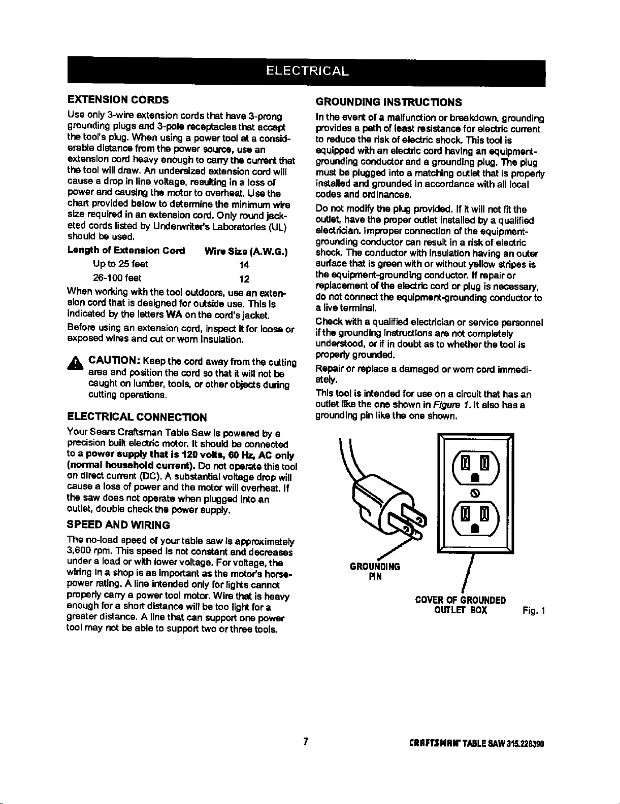
GROUNDING INSTRUCTIONS
In the event of a malfunctionor breakdown,grounding
providese path ofleast resistancefor electriccurrent
to reducethe riskof electricshock.This tool is
equippedwithan electdccord having an equipment-
groundingconductorand a groundingplug.The plug
mustbe pluggedintoa matchingoutletthat is properly
installedand groundedin accordancewith all local
codes and ordinances.
Do not modifythe plugprovided. If itwill not fitthe
outlet,havethe properoutlet installedby a qualified
electrician,improperconnectionofthe equiprnent-
groundingconductorcan result ina riskof electric
shook.The conductor with insulationhavingan outer
surfacethatisgreen withor withoutyellow stripesis
the equipment-groundingconductor. If repairor
replacementofthe electriccordor plugis necessary,
do notconnectthe equipment-groundingconductor to
a live terminal.
Check with a qualifiedelectricianor service personnel
ifthe groundinginstructionsare net completely
understood,or if in doubtas towhether the toolis
properlygrounded.
Repairor replacea damagedorwom cord immedi-
ately.
This toolis intendedfor use on a cimultthat has an
outletlikethe one shownin Figure 1. It also has •
groundingpin likethe one shown,
\
The no-load speed of yourtable saw is approximately
3,600 rpm. This speed is notconstant and decreases
undera load or withlower voltage. For voltage,the
wiringina shop is as importantas the motor's horse-
power rating.A line intended only for lightscannot
probedycarry a power tool motor.Wire thatis heavy
enoughfor a short distancewill be too lightfor a
greeterdistance. A linethat can supportone power
toolmay not be able to supporttwo orthrae tools.
GROUNDING
RN
COVEROFGROUNDED
7 ClllF1'$Nlnr TABLESAW315,228390
/
OtRLEr BOX
Fig, 1

Anti-Kickback Pawls
Toothedsafety devices behindthe blade designedto
stop a workpiece from being kickedback at the
operatorduringa ripping operation.
Arbor
The shaft on whicha blade or cuttingtool is mounted.
Bevel Cut
A cuttingoperation madewith the blade at any angle
otherthan 90° to the saw table.
Compound Cut
A cutwithboth a miterangle and a bevel angle.
Crosscut
A cuttingoperationmade acrossthe grainorthe width
of theworkpiece,
Dado
A non-throughcutthat gives a square notchor trough;
requiresa special blade.
Featherboard
A deviceto helpguide workpiecesduring ripcuts.
Freehand (for table saw)
Dangerouspracticeof making a cut withoutusingrip
or miterfences. See Safety Rules.
Gum
A sticky,sap-based residuefrom wood products.
Heel
Alignmentof the blade.
Kerr
The matedal removedbythe blade ina throughcut or
the slotproduced bythe blade In a non-throughcut.
Kickback
A hazardthat can occur when blade binds or stalls,
throwingworkpleceback toward operator.
Leading End
The end of the workpiece pushed intothe cuttingtool
first.
Miter Cut
A cuttingoperation made with the miter gage at any
angle otherthan 0°.
Molding
A non-through cutthat gives a varied shape to the
workpieceand requiresa special blade.
Push Stick
A device used to feed the workpiecethroughthe saw
blade dudngnarrowcuttingoperations. It helpskeep
the operator'shands well away from the blade,
Rabbet
A notch in the edge of a workpiece.
Rw
A cutting operation to reduce the thickness of the
workpiece in order to make thinner pieces.
Resin
A sticky,sap-bssed substance.
RIp Cut
A cutmade withthe the grain of the workpiece.
SawbladiePath
The area directlyin linewith the blade-- over,under,
behind,or in frontof it. Also, the workpiecearea
whichwillbe or has been cutbythe blade.
Set
The distance that the tip of the saw bladetoothisbent
(or set) outwardfromthe face ofthe blade.
Throw-Back
Saw throwingback a workpiece;similarto kickback.
Through Sawing
Any cuttingoperation where the blade extends
completelythroughthe workpiece.
TratIIng End
The workpiece end last cutby the blade in a rip cut.
Workplace
The itemon whichthe cuttingoperation is beingdone.
The surfacesofa workpiesaare commonlyreferredto
as faces, ends, and edges.
Worktable
The surface on whichthe workpiece restswhile
performinga cuttingoperation.
BladeArbor 5/8 in,
BLadeDiameter 10 in.
Blade "13it O° - 45 °
TableSize withouttable extensions 20 in.x 27 in.
TableSize with table extensions 44 in.x 27 in.
£11RFTSMRN" TABLE ,SAW315.228390 8
Rating 13 Amperes, 1,5 HP
(3 HP max. developed)
Input 120 V, 60 Hz -AC only
No Load Speed 3,600 RPM
Cutting Capacity with Miter at 0°/Bevel 0° 3-3/8 in.
CuttingCapacity wIth Miter at 0°/Bevel 45°: 2-1/4 in.
Your new table saw has been designedto give you
many years of highquality performance.To insure
this goal, Woparcare andtreatment is important.
Careful treatment beginswith removingall partsfrom
the cartonand checkingthem againstthe listof loose
parts.The longbox containsthe rails.The large box
holdsall other parts,whichare detailed in the Loose
Parts List,
• Separate the saw and all partsfrom the packing
materialsand check each againstthe packinglist,
especiallythe smallparts that can be hiddeninthe
packing material.
Note: Do not discardthe packing matadals untilyou
havecarefullyinspected the sew, identifiedall
parts, and satisfactorilyoperated your new saw.
WARNING: Never use gasoline,naptha, or
otherhighlyvolatile solvents.Do not ever let
brakefluids, gasoline,petroioumJoased
products,or penetrating oils contact plasticparts.
Such chemicals can weaken or destroy plastic.
• Removethe wax paper covedngon the table. Use
anyordinaryhouseholdtypegrease and spot
remover. Immediatelyapply a coat of pastawax to
thetable and table extensions.
WARNING: To preventaccidental startingthat
couldcause possible sadous personal injury,
assemble all parts to your sew beforeconnecting
itto powersupply.Saw should never be
connectedto power supplywhen you are
assemblingparts, makingadjustments,installing
or removingblades, or when notin use.
_1= WARNING: If any parts are missing,do not
operatethis tool untilthe missingpartsare
replaced. Failuretodo socould resultin possible
seriouspersonalinjury.
The followingrecommendedaccassodesare currentlyavailableat Sears Retail Stores.
Fence Guide System
Guide Master
BoxJoint& Miter Guide
UniversalJig
TaperJig
10 in.Sanding Disc
8 in.Sanding Disc
Elite Dado
ExcaliburDado
7 in.Adj. Dado 36 tip
7 in.Adj. Dado 24 tip
7 in.Stack Steel Dado
7 in.x 9/t6 in, Stack Dado
7 in. MoldingHead Set
2 BitMoldingHead Set
Saw Baskets
JointerClamps
SpecialtyThroat Plate
MiterGage Hold DownClamp
Align.A-RipXRC Rip Fence
Dust Collection System
Accessory Table
A_. WARNING: The useof attachmentsor accassedes not listedmightbe hazardous.
9 ElUlIqrENIIN"TABLESAW31.5.2,?.8,_0
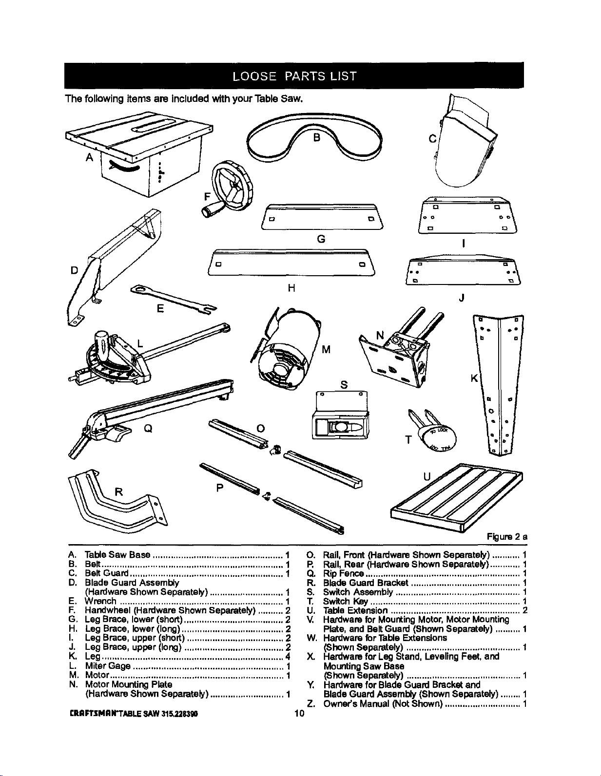
The following items are included with your Table Saw.
A
D
A. TableSaw Base ................................................... 1
B. Belt....................................................................... 1
C, BeltGuard ............................................................ 1
D, Blade Guard Assembly
(Hardware Shown Separately) ............................. 1
E, Wrench ................................................................ 1
F, Handwheel (Hardware Shown Separately) .......... 2
G, LegBrace, lower (short)....................................... 2
H, Leg Brace, lower(long)........................................ 2
I, Leg Brace, upper (short) ...................................... 2
J. Leg Brace, upper (long) ....................................... 2
K. Leg ....................................................................... 4
L. Miter Gage ........................................................... 1
M. Motor.................................................................... 1
N. Motor MountingPlate
(Hardware Shown Separately) ............................. 1
CRnFTSMnN'TABLESAW315,228,390
O. Rail,Front (Hardware Shown Separately) ........... 1
R Rail, Rear (Hardware Shown Separately)............ 1
Q. Rip Fence............................................................. 1
R. Blade Guard Bracket........................................... 1
S. Switch Assembly ................................................. 1
T. Switch Key........................................................... 1
U, Table Extension ................................................... 2
V, Hardware for MountingMotor,Motor Mounting
Plate, and BeltGuard (ShownSeparately) .......... 1
W. Hardware for Table Extensions
(ShownSeparately) ............................................. 1
X. Hardware for Leg Stand, Leveling Feet, and
MountingSaw Base
(Shown Separately) ............................................. 1
Y. Hardwarefor BladeGuard Bracketand
BladeGuardAssembly(Shown Separately) ........ 1
Z. Owner's Manual (Not Shown) .............................. 1
10
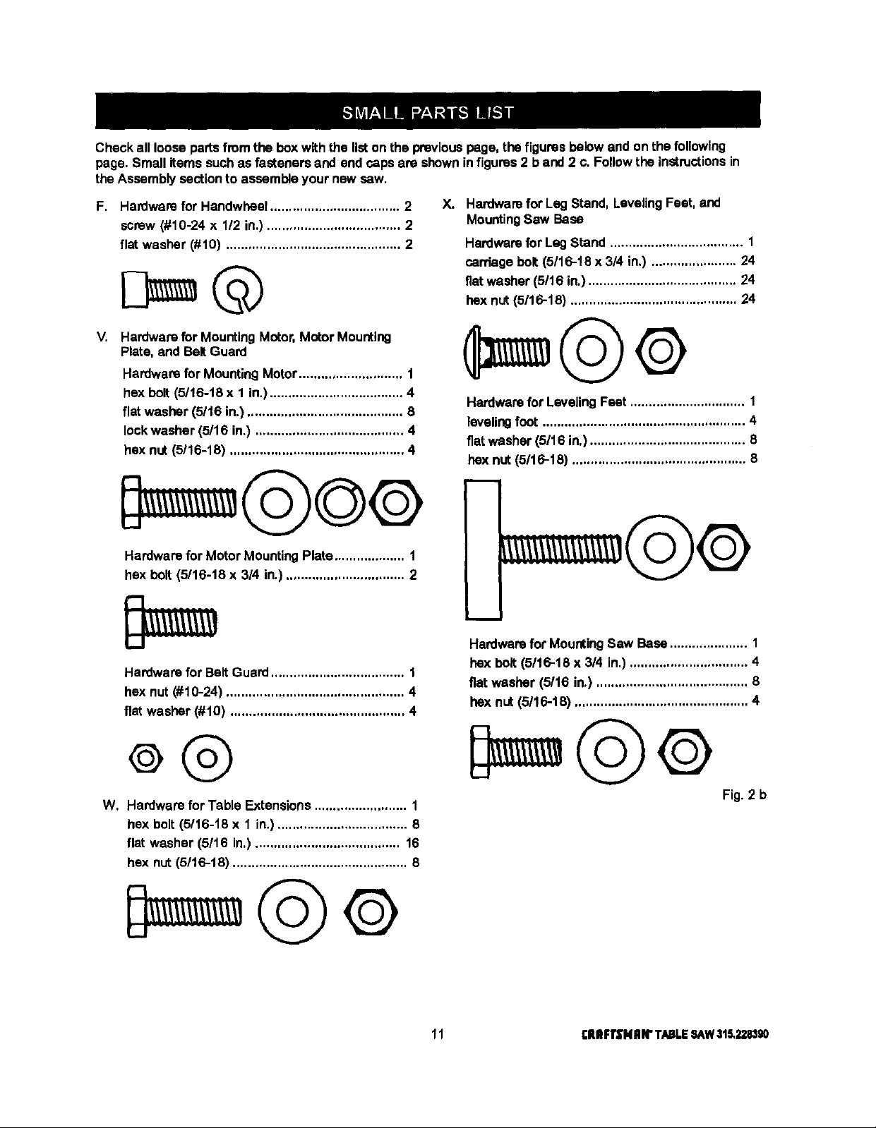
Checkallloosepartsfromtheboxwiththelistonthepreviouspage,thefiguresbelowandonthefollowing
page.Smallitems such as fasteners and end capsare shownin figures2 b and 2 c. Follow the instructionsin
the Assembly sectionto assemble your new sew.
F. Hardware for Handwheel................................... 2
screw (#10-24 x 1/2 in.) .................................... 2
flat washer (#10) ............................................... 2
V. Hardware for MountingMotor,Motor Mounting
Plate, and BeltGuard
Hardwarefor MountingMotor............................ 1
hex bolt (5116-18x 1 in.).................................... 4
flat washer (5/16 in.) .......................................... 8
lockwasher (5/16 in.) ........................................ 4
hex nut (5116-18) ............................................... 4
Hardware for Motor MountingPlate................... 1
hex bolt (5/16-18 x 3/4 in.)................................ 2
X. Hardwarefor Leg Stand, LevelingFeet, and
MountingSaw Base
Hardwarefor LagStand .................................... 1
carriage bolt (5/16-t8 x 3/4 in.) ....................... 24
fiatwasher (5/16 in.)........................................ 24
hex nut (5116-18) ............................................. 24
Hardwarefor LevelingFeet ............................... 1
levelingfoot ....................................................... 4
flatwasher (5/16 in.).......................................... 8
hex nut (5116-18) ............................................... 8
i
m
Hardware for Belt Guard.................................... 1
hex nut (#10-24) ................................................ 4
flat washer (#10) ............................................... 4
W, Hardware for Table Extensions ......................... 1
hex bolt (5/16-18 x 1 in.) ................................... 8
flat washer (5/16 in.)....................................... 16
hex nut (5/16-18) ............................................... 8
Hardwarefor MountingSaw Base ..................... 1
hex bolt (5116-18 x 3/4 in.) ................................ 4
fiat washer (5/16 in.) ......................................... 6
hex nut (5/16-18) ............................................... 4
Fig. 2 b
11 rlUIFTSNRIrTABLESAW315,228,190
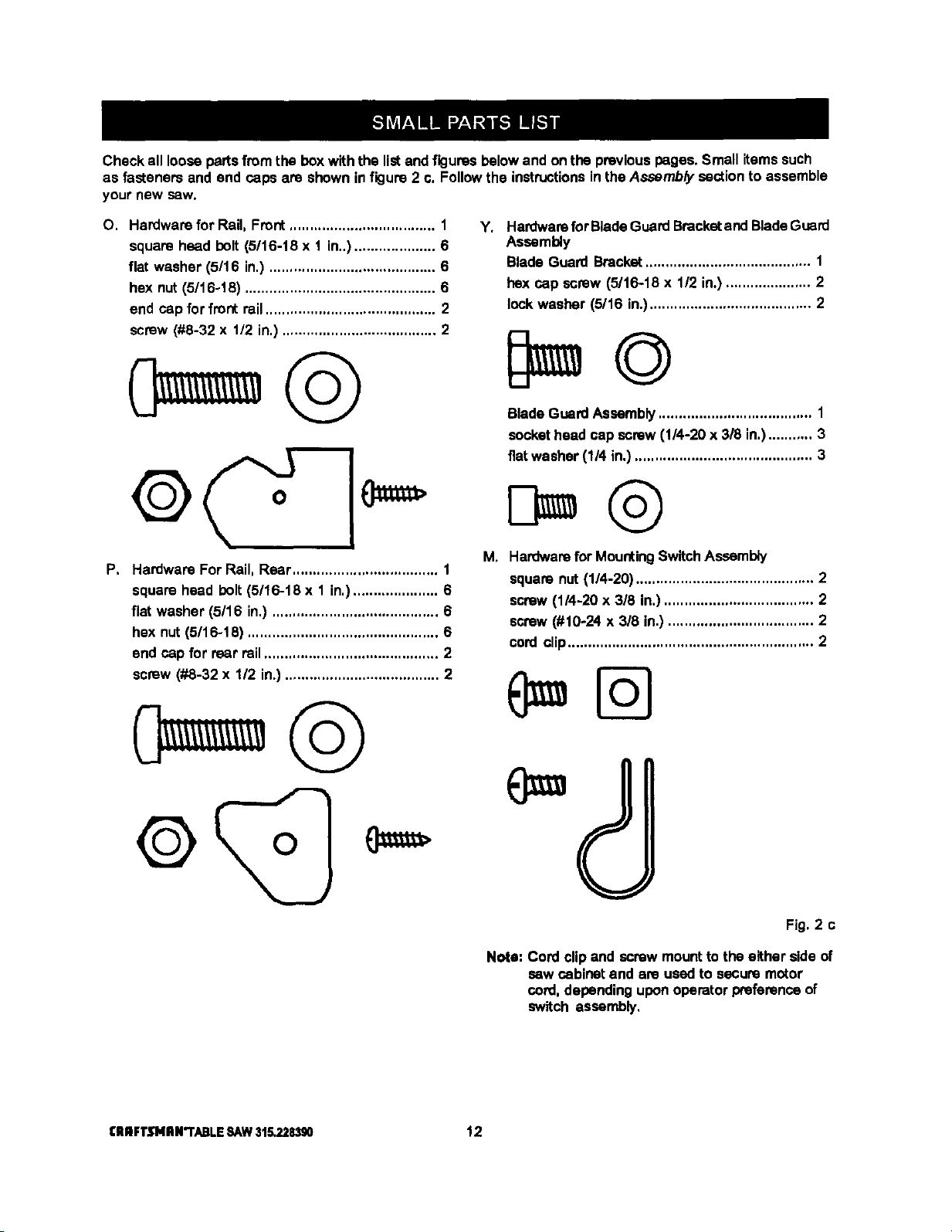
Checkalllooseparsfromtheboxwiththelistandfiguresbelowandonthepreviouspages.Smallitemssuch
asfasteners and end caps are shownin figure 2 c. Followthe instructionsin the Assembly section to assemble
your new sew.
O. Hardware for Rail, Front.................................... 1
square head holt (5/16-18 x 1 in..).................... 6
flat washer (5/16 in.) ......................................... 6
hex nut (5/16-18) ............................................... 6
end cap for front rail.......................................... 2
screw (#8-32 x 112in.) ...................................... 2
P, Hardware For Rail, Rear.................................... 1
square head bolt(5/16-18 x 1 in,)..................... 6
flat washer (5/16 in.) ......................................... 6
hex nut(5/16-18) ............................................... 6
end cap for rear rail........................................... 2
screw (#8-32 x 1/2 in.) ...................................... 2
Hardwarefor BladeGuardBracketand BladeGuard
Y*
Assembly
Blade Guard Bracket......................................... 1
hex cap screw (5/16-18 x 112in.) ..................... 2
lock washer (5/16 in.)........................................ 2
BladeGuardAssembly...................................... 1
sockethead cap screw (1/4-20 x 318in.)........... 3
fiatwasher (1/4 in.)............................................ 3
i_
Hardwarefor MountingSwitchAssembly
squara nut (1/4-20) ............................................ 2
screw(1/4-20 x 3/8 in.)..................................... 2
screw(#10-24 x 3/8 in.) .................................... 2
cord clip............................................................. 2
I:ll n FTJflNII N"I'ABLE SAW 315.228390 12
(
Fig. 2 c
Note: Cord clipand screw mountto the either side of
saw cabinet and are usedto secure motor
cord,dependinguponoperator preferancaof
switch assembly,
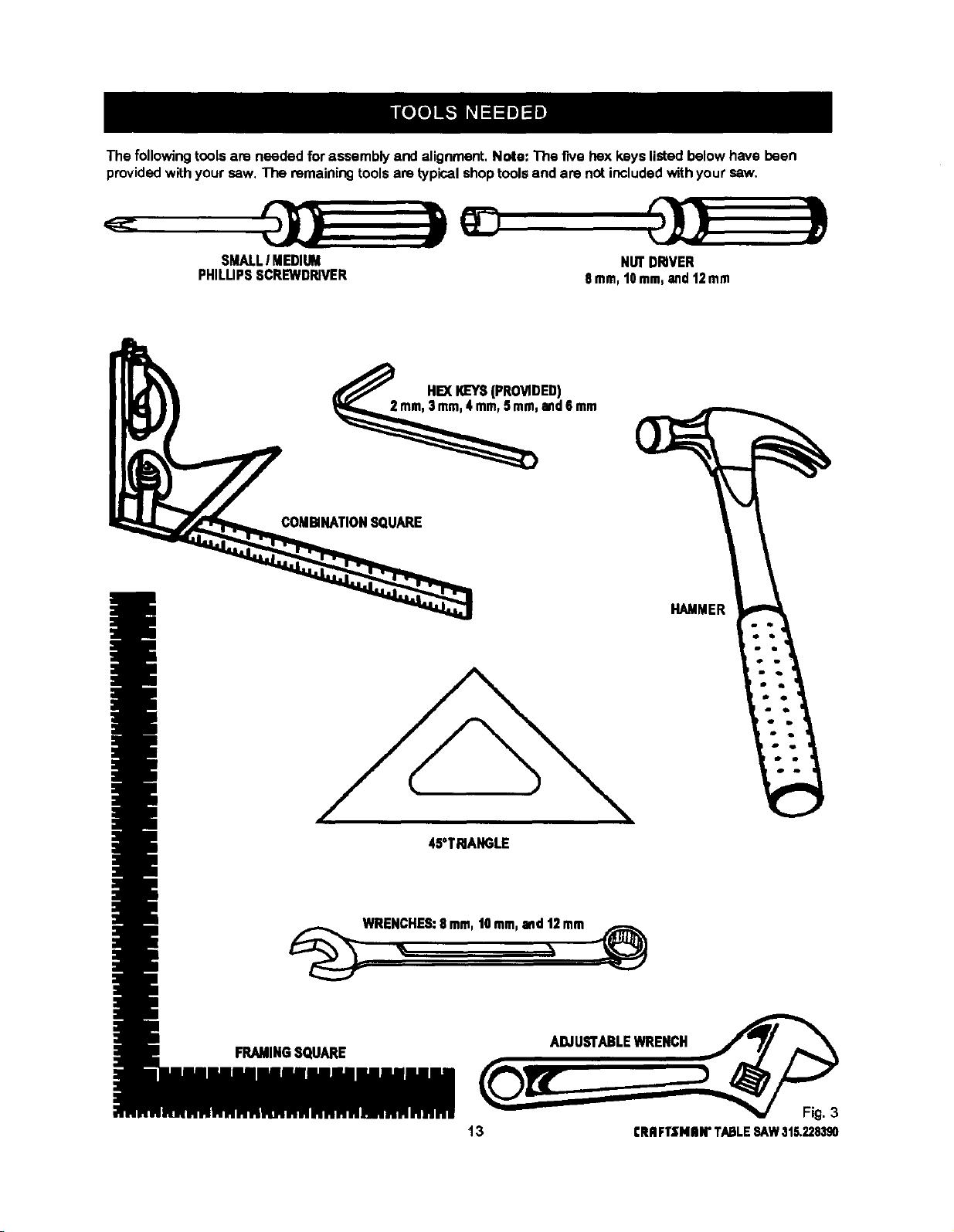
The following tools are needed for assembly and alignment, Note: The five hex keys listed below have been
provided with your saw. The remaining tools are typical shop tools and are not included with your saw.
SMALLI MEDIUM
PHILUPSSCREWDRIVER
COMBINATIONSQUARE
NUTDRIVER
8ram,t0 mm,and12mm
HEXI_EYS(PROVIDED)
and6mm
HAMMER
45°TRIANGLE
_WRE_HES: 8.m, ,Omm,and_2mm _¢_
FRAMINGSQUARE ADJUSTABLEWRENCH
13 CRRFTSNIIW TABLESAW315.228390
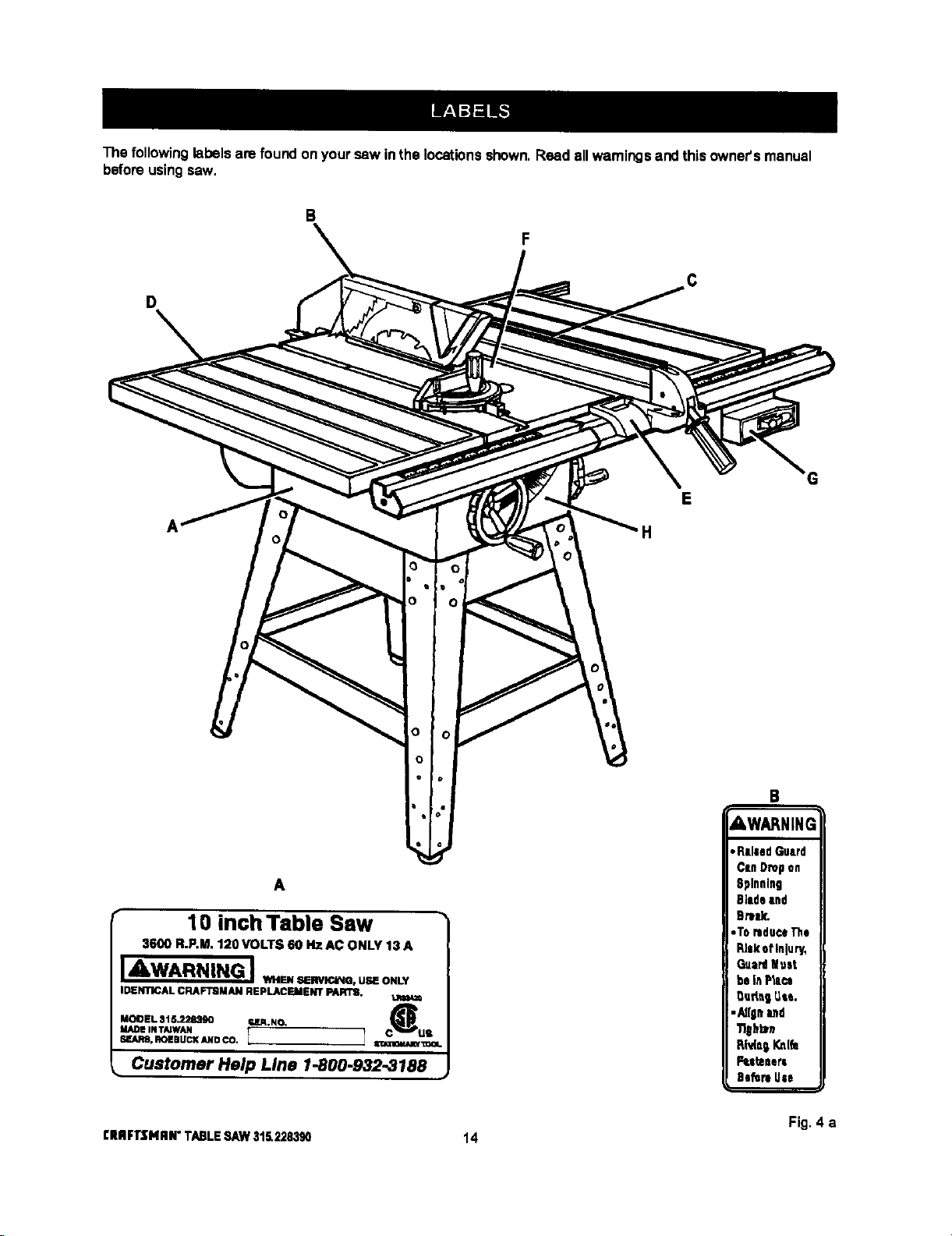
The following labelsare found onyour saw inthe locationsshown.Read allwarningsand this owner'smanual
beforeusingsaw.
B
D
E
H
A
10 inch Table Saw
3600 R.P.M. 1;!0 VOLTS 60 HZ AC ONLY 13 A
JAWARNING J,,....._--.. u.o._,
IDENTICAL CRAFTBMAN REPLACEMENT PARTS.
MODEL 315.228390 ra,lR.NO. C_
MADE IN TAIWAN US
SF.ARS.ROEBUCI(ANDCO. I 1 S_I_.-lCaUUWI:=OI.
Customer Help Line 1-800.932.3188
CRRFI"$NRN"TABLESAW315.228390 14
B
AWARNING
Fig. 4 a
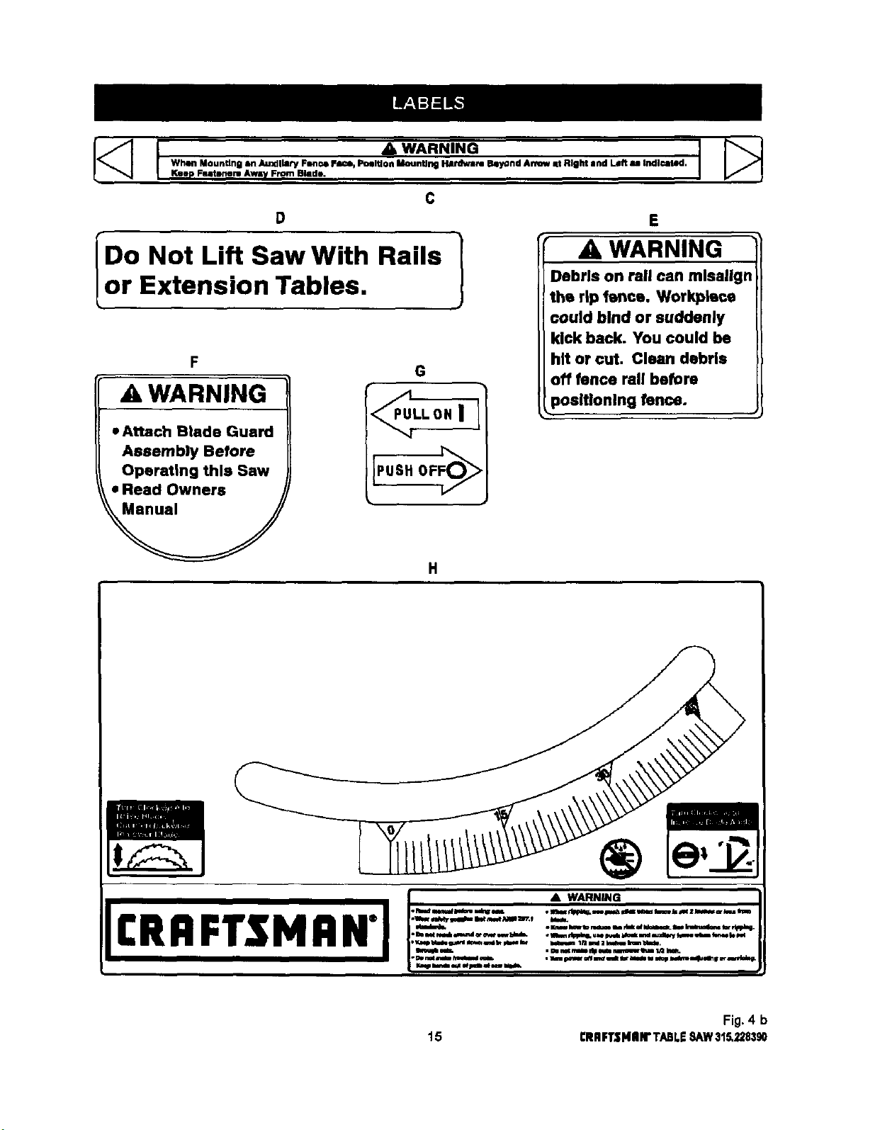
C
• D •
IDo Not Lift Saw With Rails 1
_or Extension Tables, J
F
• G
A WARNING
• Attach Btade Guard
Assembly Before
Operating this Saw
• Read Owners
E
WARNING
Debris on Pall can mlsallgn
the rip fence. Workplace
could bind or suddenly
kick back. You could be
hit or cut, Clean debris
off fence Pall before
3ositlonlng fence.
£RRFr$ H RN"FI:_-:z: .'i_-_-"____:_=.J
Fig. 4 b
15 CRRFTZNIIN"TABLE8/kW315.228,190
 Loading...