

Owner'sManual
P R 0 F E S S I
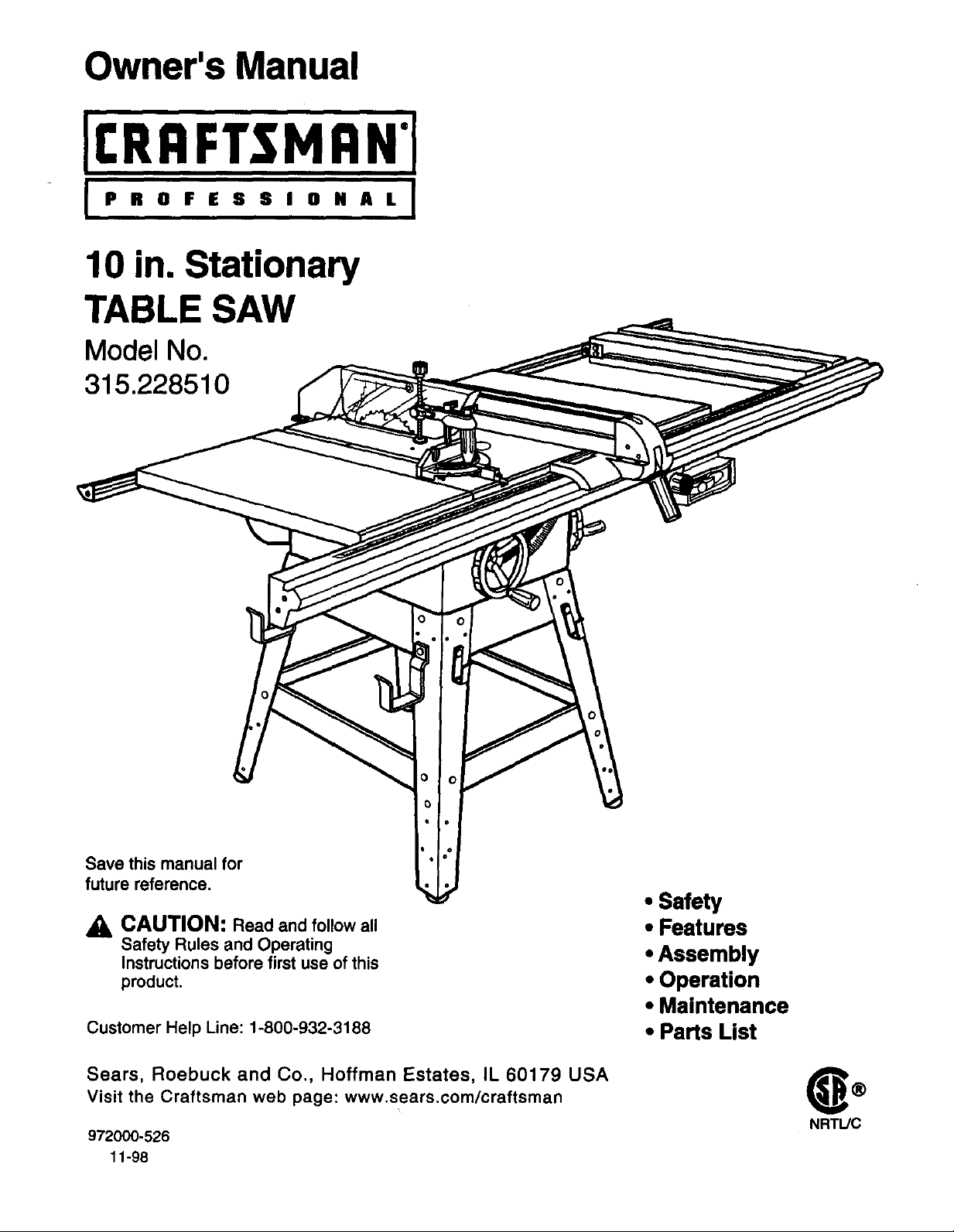
10 in. Stationary
TABLE SAW
Model No.
315.228510
Save this manual for
future reference.
CAUTION: Read and follow all
Safety Rules and Operating
Instructions before first use of this
product.
Customer Help Line: 1-800-932-3188
Sears, Roebuck and Co., Hoffman Estates, IL 60179 USA
Visit the Craftsman web page: www.sears.com/craftsman
972000-526
11-98
• Safety
• Features
• Assembly
• Operation
• Maintenance
• Parts List
®
NRTUC
FULL ONE YEAR WARRANTY ON CRAFTSMAN TABLE SAW
If this I:RRFTSMRN Table Saw fails due to a defect inmaterial or workmanship within one year from the date of
purchase, Sears will repair it, free of charge.
Contact a Sears Service Center for repair.
If this product is used for commercial or rental purposes, this warranty applies only for 90 days from the date of
purchase.
This warranty gives you specific legal rights, and you may also have other rights which vary from state to state.
Sears, Roebuck and Co., Dept. 817WA, Hoffman Estates, IL 60179
Your saw has many features for making cutting operations more pleasant and enjoyable. Safety, performance
and dependability have been given top priority in the design of this saw making it easy to maintain and operate.
,d_ CAUTION: Carefully read through this entire owner's manual before using your new saw. Pay close
attention to the Rules For Safe Operation, and all Safety Alert Symbols, including Danger, Warning and
Caution. If you use your saw properly and only for what it is intended, you will enjoy years of safe, reliable
service.
,_ Look for this symbol to point out important safety precautions. It means attention!!! Your safety is involved.
,_ WARNING:
The operation of any power tool can result in foreign objects being thrown into your eyes,
which can result in severe eye damage. Before beginning power tool operation, always
wear safety goggles or safety glasses with side shields and a full face shield when needed.
We recommend a Wide Vision Safety Mask for use over eyeglasses or standard safety
glasses with side shields, available at Sears Retail Stores.
• Warranty and Introduction .............................................................................................................................. 2
• Table Of Contents ....................................................................................................................................... 2-3
• Rules For Safe Operation ........................................................................................................................... 4-6
• Electrical ......................................................................................................................................................... 7
• Glossary and Product Specifications ............................................................................................................. 8
• Unpacking and Accessories ........................................................................................................................... 9
• Loose Parts List ....................................................................................................................................... 10-11
• Small Parts List ....................................................................................................................................... 11-13
• Tools Needed ............................................................................................................................................... 14
• Labels ...................................................................................................................................................... 15-16
• Features .................................................................................................................................................. 17-18
• Assembly ................................................................................................................................................. 19-32
Installing Handwheels on Table Saw Base .................................................................................................. 19
rRIIFT.$MAN" TABLESAW315.228510 2
Assembling Leg Stand ............................................................................................................................ 19-20
Mounting the Leg Stand on the Table Saw Base ........................................................................................ 20
Assembling Table Extensions ...................................................................................................................... 21
Aligning Table Extensions ............................................................................................................................ 21
Installing the Rear Rail ................................................................................................................................. 22
Installing the Front Rail ................................................................................................................................ 23
Installing the Separator Channel ............................................................................................................. 23-24
Assembling Storage Hangers ...................................................................................................................... 24
Installing the Micro-Adjust ....................................................................................................................... 24-25
Aligning Rip Fence and Front Rail ............................................................................................................... 25
Mounting the Motor and Switch .................................................................................................................... 26
Installing the Belt and Belt Guard ................................................................................................................ 27
Installing the Blade Guard ............................................................................................................................ 28
Checking the Throat Plate ............................................................................................................................ 29
Aligning the Riving Knife with the Blade ...................................................................................................... 29
Checking Rip Fence and Blade Alignment .................................................................................................. 30
Changing the Motor Voltage ........................................................................................................................ 31
Assembling the Hold Down Clamp on the Miter Gage ................................................................................ 32
• Adjustments ............................................................................................................................................. 33-36
Replacing the Blade ..................................................................................................................................... 33
Heeling (Paralleling) the Sawblade to Miter Gage Groove .......................................................................... 34
Setting the Bevel Stops and Indicator .......................................................................................................... 35
Adjusting the Miter Gage .............................................................................................................................. 36
Removing / Replacing the Throat Plate ....................................................................................................... 36
• Basic Operation of the Table Saw .......................................................................................................... 37-46
Causes of Kickback ...................................................................................................................................... 37
Avoiding Kickback ........................................................................................................................................ 37
Cutting Aids .................................................................................................................................................. 37
Resetting Thermal Overload Protector ........................................................................................................ 38
Causes of Overload ...................................................................................................................................... 38
Types of Cuts ............................................................................................................................................... 39
Making a Cross Cut ................................................................................................................................. 40-41
Making a Rip Cut .......................................................................................................................................... 41
Making a Miter Cut ....................................................................................................................................... 42
Making a Bevel Cross Cut ....................................................................................................................... 42-43
Making a Bevel Rip Cut ................................................................................................................................ 43
Making a Compound (Bevel) Miter Cut ........................................................................................................ 44
Making a Large Panel Cut ............................................................................................................................ 45
Making a Dado Cut ....................................................................................................................................... 46
Making a Non-Through Cut .................. ,....................................................................................................... 46
• Maintenance ................................................................................................................................................. 47
• Lubrication .................................................................................................................................................... 47
• Troubleshooting ....................................................................................................................................... 48-50
• Exploded View and Repair Parts List ...................................................................................................... 54-71
• Parts Ordering / Service ................................................................................................................... back page
3 rRRFTSMIIN" TABLESAW315.228510
The purpose of safety symbols is to attract your attention to possible dangers. The safety symbols, and the
explanations with them, deserve your careful attention and understanding. The safety warnings do not by
themselves eliminate any danger. The instructions or warnings they give are not substitutes for proper accident
prevention measures.
SYMBOL
A
A
A
Note: Advises you of information or instructionsvital to the operation or maintenance of the equipment.
MEANING
SAFETY ALERT SYMBOL
Indicates danger, warning, or caution. May be used in conjunction with other symbols or
pictographs.
DANGER: Failure to obey a safety warning will result in serious injury to yourself or to others.
Always follow the safety precautions to reduce the risk of fire, electric shock and personal injury.
WARNING: Failure to obey a safety warning can result in serious injury to yourself or to others.
Always follow the safety precautions to reduce the risk of fire, electric shock and personal injury.
CAUTION: Failure to obey a safety warning may result in property damage or personal injury to
yourself or to others. Always follow the safety precautions to reduce the risk of fire, electric shock
and personal injury.
IMPORTANT
Servicing requires extreme care and knowledge of the
system and should be performed only by a qualified
service technician. For service we suggest you return
the tool to your nearest Sears store or repair center.
Always use original factory replacement parts when
servicing.
WARNING: Do not attempt to operate this tool
A
until you have read thoroughly and understand
completely all instructions, safety rules, etc.
contained in this manual. Failure to comply can
result in accidents involving fire, electrical shock,
or serious personal injury. Save the owner's
manual and review frequently for continuing safe
operation, and instructing others who may use
this tool.
READ ALL INSTRUCTIONS
• KNOW YOUR POWER TOOL. Read the owner's
manual carefully. Learn the saw's applications
and limitations as well as the specific potential
hazards related to this tool.
DO NOT USE IN DANGEROUS ENVIRON-
MENT, Do not use power tools near gasoline or
other flammable liquids, in damp or wet loca-
tions, or expose them to rain. Keep the work
area well lit.
• •AKE WORKSHOP CHILD-PROOF with
padlocks and master switches or by removing
starter keys.
• KEEP CHILDREN AND VISITORS AWAY. All
visitors should wear safety glasses and be kept a
safe distance from work area. Do not let visitors
contact tool or extension cord while operating.
• KEEP THE WORK AREA CLEAN. Cluttered
work areas and work benches invite accidents,
DO NOT leave tooJsor pieces of wood on the
saw while it is in operation.
• AINTAIN TOOLS WITH CARE. Keep tools
sharp and clean for better and safer perfor-
mance. Follow instructions for lubricating and
changing accessories.
USE THE RIGHT TOOL FOR THE JOB. Do not
force the tool or attachment to do a job it was not
designed for. Use it only the way it was intended.
DRESS PROPERLY. Do not wear loose clothing,
gloves, neckties, rings, bracelets, or other
jewelry. They can get caught and draw you into
moving parts. Rubber gloves and nonslip foot-
wear are recommended. Also wear protective
hair covering to contain long hair.
ALWAYS WEAR SAFETY GLASSES WITH
SIDE SHIELDS. Everyday eyeglasses have only
impact-resistant lenses; they are NOT safety
glasses.
NEVER STAND ON TOOL. Serious injury could
occur ifthe tool is tipped or if the blade is unin-
tentionally contacted.
tRRFTSMAH" TABLESAW315.228510 4
RULES FOR SAFE OPERATION (Continued)
• DO NOT OVERREACH. Keep proper footing and
balance at all times.
SECURE WORK. Use clamps or a vise to hold
work when practical. It's safer than using your
hand and frees both hands to operate tool.
USE THE PROPER EXTENSION CORD. Make
sure your extension cord is in good condition.
Use only a cord heavy enough to carry the
current your product will draw. An undersized
cord will cause a drop in line voltage resulting in
loss of power and overheating. A wire gage size
(A.W.G.) of at least 14 is recommended for an
extension cord 25 feet or less in length. If in
doubt, use the next heavier gage. The smaller
the gage number, the heavier the cord.
AVOID ACCIDENTAL STARTING. Be sure
switch is off when plugging in.
m
REMOVE WRENCHES AND ADJUSTING
KEYS. Get in the habit of checking - before
turning on tool - that hex keys and adjusting
wrenches are removed from tool.
m
CHECK DAMAGED PARTS. Before using the
tool again, check any damaged parts, including
guards, for proper operation and performance.
Check alignment of moving parts, binding of
moving parts, breakage of parts, saw stability,
mounting and any other conditions that may
affect its operation. A damaged part must be
properly repaired or replaced by a qualified
service technician at a Sears store or repair
center to avoid risk of personal injury.
USE ONLY CORRECT BLADES. Use the right
blade size, style and cutting speed for the
material and the type of cut. Blade teeth should
point down toward the front of the table.
USE RECOMMENDED ACCESSORIES. Using
improper accessories may risk injury.
USE ONLY SEARS REPLACEMENT PARTS.
All repairs, whether electrical or mechanical,
should be made by a qualified service technician
at a Sears store or repair center.
• KEEP GUARDS IN PLACE and in good working
order. This includes the blade guard, riving knife,
and anti-kickback pawls.
CHECK DIRECTION OF FEED. Feed work into
a blade or cutter against the direction of rotation
of the blade or cutter only.
DISCONNECT ALL TOOLS. When not in use,
before servicing, or when changing attachments,
blades, bits, cutters, etc., all tools should be
disconnected from power supply.
DO NOT FORCE THE TOOL. it will do the job
better and more safely at the rate for which it
was designed.
• NEVER LEAVE TOOL RUNNING UNAT-
TENDED. TURN THE POWER OFF. Do not
leave tool until it comes to a complete stop.
• BEFORE MOUNTING, DISCONNECTING OR
REMOUNTING THE MOTOR; unplug the saw
and remove the switch key.
WARNING: When servicing, use only identical
A
Craftsman replacement parts. Use of any other
parts may create a hazard or cause product
damage.
NEVER USE THIS TOOL IN AN EXPLOSIVE
ATMOSPHERE. Normal sparking of the motor
could ignite fumes,
MAKE SURE THE WORK AREA HAS AMPLE
LIGHTING to see the work and that no obstruc-
tions will interfere with safe operation BEFORE
performing any work using this tool.
DO NOT USE TOOL IF SWITCH DOES NOT
TURN IT ON AND OFF. Have defective switches
replaced by a qualified service technician at a
Sears store or repair center.
GUARD AGAINST ELECTRICAL SHOCK by
preventing body contact with grounded surfaces
such as pipes, radiators, ranges, refrigerator
enclosures.
GROUND ALL TOOLS. See Electrical page.
WEAR A DUST MASK to keep from inhaling fine
particles.
PROTECT YOUR HEARING. Wear hearing
protection during extended periods of operation.
DO NOT OPERATE THIS TOOL WHILE UN-
DER THE INFLUENCE OF DRUGS, ALCOHOL,
OR ANY MEDICATION.
STAY ALERT AND EXERCISE CONTROL.
Watch what you are doing and use common
sense. Do not operate tool when you are tired.
Do not rush.
• AVOID AWKWARD OPERATIONS AND HAND
POSITIONS where a sudden slip could cause
your hand to move into the blade. ALWAYS
make sure you have good balance.
• ALWAYS SUPPORT LARGE WORK PIECES
while cutting to minimize riskof blade pinching
and kickback. Saw may slip, walk or slide while
cutting large or heavy boards.
5 CRAFTSMAN"TABLESAW315.228510
RULES FOR SAFE OPERATION (Continued)
GUARD AGAINST KICKBACK. Kickback can
occur when the blade stalls, driving the work
piece back toward the operator. It can pull your
hand into the blade, resulting in serious personal
injury. Stay out of the blade path and turn switch
off immediately if blade binds or stalls.
• USE A SUPPORT FOR THE SIDES AND BACK
OF THE SAW TABLE when sawing wide or long
workpieces. Use a sturdy "outrigger" support if a
table extension is more than 24 inches long and
is attached to the saw, to prevent tipping.
• CUT ONLY WOOD, PLASTIC OR WOOD-LIKE
MATERIALS. Do not cut metal.
• NEVER cut more than one piece at a time. DO
NOT STACK more than one workpiece on the
saw table at a time.
DO NOT REMOVE THE SAW'S BLADE
GUARDS. Never operate the saw with any guard
or cover removed. Make sure all guards are
operating properly before each use.
NEVER PERFORM ANY OPERATION FREE-
HAND. Always place the workpiece to be cut on
the saw table and position it firmly against the
fence as a backstop.
• USE THE RIP FENCE. Always use a fence or
straight edge guide when ripping.
• BEFORE MAKING A CUT, be sure all adjust-
ments are secure.
• BE SURE THE BLADE PATH IS FREE OF
NAILS. Inspect for and remove all nails from
lumber before cutting. •
• BE SURE THE BLADE CLEARS THE
WORKPIECE. Never start the saw with the blade
touching the workpiece.
• KEEP HANDS AWAY FROM CUTTING AREA.
Do not reach underneath work or in blade cutting •
path with your hands and fingers for any reason.
Always turn the power off.
• USE A PUSHBLOCK OR PUSH STICK for _•
workpieces so small that your fingers go under
the blade guard. NEVER TOUCH BLADE or
other moving parts during use, for any reason.
ALLOW THE MOTOR TO COME UP TO FULL
SPEED before starting a cut to avoid blade
binding or stalling.
ALWAYS PUSH THE WORKPIECE; never pull it
toward the saw,
DO NOT FEED THE MATERIAL TOO QUICKLY.
Do not force the workpiece against the blade.
ALWAYS TURN OFF SAW before disconnecting
it, to avoid accidental starting when reconnecting
to power supply. NEVER leave the table saw
unattended while connected to a power source.
BEFORE CHANGING THE SETUP, REMOVING
COVERS, GUARDS, OR BLADE; unplugthe
saw and remove the switch key.
KEEP TOOL DRY, CLEAN, AND FREE FROM
OIL AND GREASE. Always use a clean cloth
when cleaning. Never use brake fluids, gasoline,
petroleum-based products, or any solvents to
clean tool.
KEEP BLADES CLEAN, SHARP AND WITH
SUFFICIENT SET. Sharp blades minimize
stalling and kickback.
USE ONLY OUTDOOR EXTENSION CORDS.
Use only extension cords with the marking
"Acceptable for use with outdoor appliances;
store cords indoors while not in use." Use
extension cords with an electrical rating not less
than the saw's rating. Always disconnect the
extension cord from the outlet before disconnect-
ingthe product from the extension cord.
INSPECT TOOL CORDS AND EXTENSION
CORDS PERIODICALLY and, if damaged, have
repaired by a qualified service technician at a
Sears store or repair center. Stay constantly
aware of cord location and keep it well away
from the moving blade.
DO NOT ABUSE CORD. Never yank cord to
disconnect it from receptacle. Keep cord from
heat, oil,and sharp edges.
SAVE THESE INSTRUCTIONS. Refer to them
frequently and use to instruct other users. If you
loan someone this toot, loan them these instruc-
tions also.
_k WARNING: Blade coasts after being turned off.
SAVE THESE INSTRUCTIONS
rRRFlrSMIIN" TABLESAW315.228510 6
EXTENSION CORDS
Use only 3-wire extension cords that have 3-prong
grounding plugs and 3-pole receptacles that accept
the tool's plug. When using a power tool at a consid-
erable distance from the power source, use an
extension cord heavy enough to carry the current that
the tool will draw. An undersized extension cord will
cause a drop in line voltage, resulting in a loss of
power and causing the motor to overheat. Use the
chart provided below to determine the minimum wire
size required in an extension cord. Only round jack-
eted cords listed by Underwdter's Laboratories (UL)
should be used.
Length of Extension Cord
Up to 25 feet
26-100 feet 12
When working with the tool outdoors, use an exten-
sion cord that is designed for outside use. This is
indicated by the letters WA on the cord's jacket.
Before using an extension cord, inspect it for loose or
exposed wires and cut or worn insulation.
_1, CAUTION: Keep the cord away from the cutting
area and position the cord so that it will not be
caught on lumber, tools, or other objects during
cutting operations.
ELECTRICAL CONNECTION
Wire Size (A.W.G.)
14
GROUNDING INSTRUCTIONS
In the event of a malfunction or breakdown, grounding
provides a path of least resistance for electric current
to reduce the risk of electric shock. This tool is
equipped with an electric cord having an equipment-
grounding conductor and a grounding plug. The plug
must be plugged into a matching outlet that is properly
installed and grounded in accordance with all local
codes and ordinances.
Do not modify the plug provided. If it will not fit the
outlet, have the proper outlet installed by a qualified
electrician. Improper connection of the equipment-
grounding conductor can result in a risk of electric
shock. The conductor with insulation having an outer
surface that is green with or without yellow stripes is
the equipment-grounding conductor. If repair or
replacement of the electric cord or plug is necessary,
do not connect the equipment-grounding conductor to
a live terminal.
Check with a qualified electrician or service personnel
if the grounding instructions are not completely
understood, or if in doubt as to whether the tool is
properly grounded.
Repair or replace a damaged or worn cord immedi-
ately.
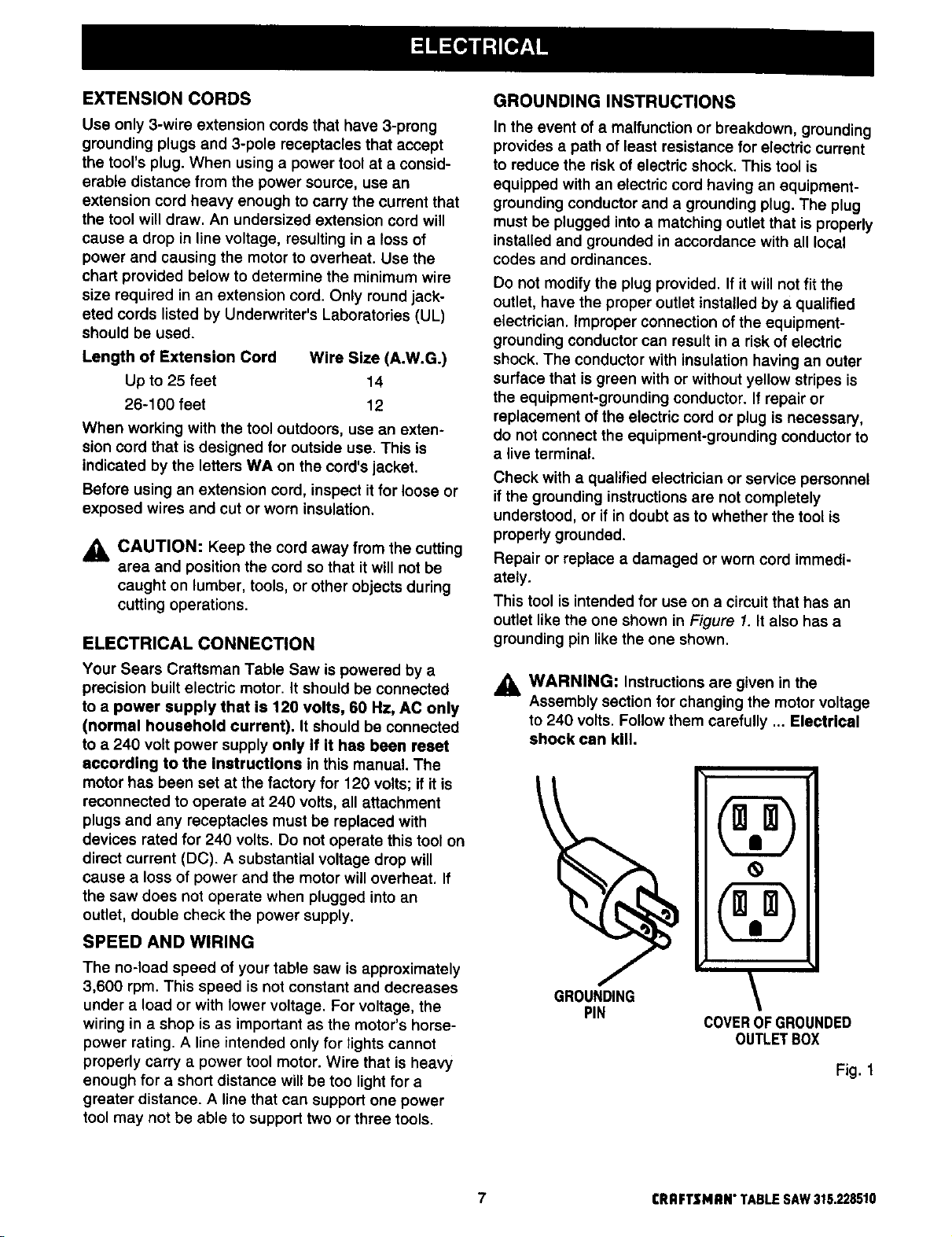
This tool is intended for use on a circuit that has an
outlet like the one shown in Figure 1. It also has a
grounding pin like the one shown.
Your Sears Craftsman Table Saw is powered by a
precision built electric motor. It should be connected
to a power supply that is 120 volts, 60 Hz, AC only
(normal household current). It should be connected
to a 240 volt power supply only if it has been reset
according to the instrucUons in this manual. The
motor has been set at the factory for 120 volts; if it is
reconnected to operate at 240 volts, all attachment
plugs and any receptacles must be replaced with
devices rated for 240 volts. Do not operate this tool on
direct current (DC). A substantial voltage drop will
cause a loss of power and the motor will overheat. If
the saw does not operate when plugged into an
outlet, double check the power supply.
SPEED AND WIRING
The no-load speed of your table saw is approximately
3,600 rpm. This speed is not constant and decreases
under a load or with lower voltage. For voltage, the
wiring in a shop is as important as the motor's horse-
power rating. A line intended only for lights cannot
properly carry a power tool motor. Wire that is heavy
enough for a short distance will be too light for a
greater distance. A line that can support one power
tool may not be able to support two or three tools.
_1_ WARNING: Instructions are given in the
Assembly section for changing the motor voltage
to 240 volts. Follow them carefully ... Electrical
shock can kill.
\
COVEROFGROUNDED
OUTLETBOX
Fig. 1
7 CRRFTSMRN"TABLESAW315.228510
Anti-Kickback Pawls
Toothed safety devices behind the blade designed to
stop a workpiece from being kicked back at the
operator during a ripping operation.
Arbor
The shaft on which a blade or cutting tool is mounted.
Bevel Cut
A cutting operation made with the blade at any angle
other than 90" to the saw table.
Compound Cut
A cut with both a miter angle and a bevel angle.
Crosscut
A cutting operation made across the grain or the width
of the workpiece.
Dedo
A non-through cut that gives a square notch or trough;
requires a special blade.
Feetherboard
A device to help guide workpieces during rip cuts.
Freehand (for table saw)
Dangerous practice of making a cut without using rip
or miter fences. See Safety Rules.
Gum
A sticky, sap-based residue from wood products.
Heel
Alignment of the blade.
Kerr
The material removed by the blade in a through cut or
the slot produced by the blade ina non-through cut.
Kickback
A hazard that can occur when blade bindsor stalls,
throwing workpiece back toward operator.
Leading End
The end of the workpiece pushed into the cutting tool
first.
Miter Cut
A cutting operation made with the miter gage using
any angle other than 0" on the miter gage.
Molding
A non-through cut that gives a varied shape to the
workpiece and requires a special blade.
Push Stick
A device used to feed the workpiece through the saw
blade during narrow cutting operations. It helps keep
the operator's hands well away from the blade.
Rabbet
A notch in the edge of a workpiece.
Resaw
A cutting operation to reduce the thickness ofthe
workpiece inorder to make thinner pieces.
Resin
A sticky, sap-based substance.
Rip Cut
A cut made with the the grain ofthe workpiece.
Sawblade Path
The area directly in line with the blade -- over, under,
behind, or in front of it. Also, the workpiece area
which will be or has been cut by the blade.
Set
The distance that the tip of the saw blade tooth is bent
(or set) outward from the face of the blade.
Throw-Back
Saw throwing back a workpiece; similar to kickback.
Through Sawing
Any cutting operation where the blade extends
completely through the workpiece.
Trailing End
The workpiece end last cut by the blade in a ripcut,
Workpiece
The item on which the cutting operation is being done.
The surfaces of a workpiece are commonly referred to
as faces, ends, and edges.
Worktable
The surface on which the workpiece rests while
performing a cutting operation.
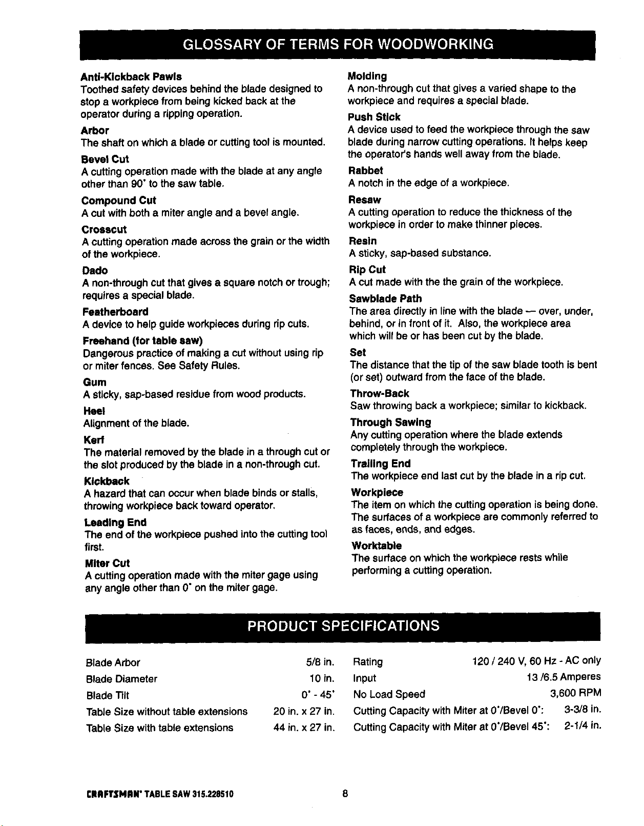
Blade Arbor 518 in.
Blade Diameter 10 in.
Blade "lilt 0" - 45"
Table Size without table extensions 20 in. x 27 in.
Table Size with table extensions 44 in. x 27 in,
CRAFTSMIIN" TABLE SAW315.228510 8
Rating 120/240 V, 60 Hz -AC only
Input 13/6.5 Amperes
No Load Speed 3,600 RPM
Cutting Capacity with Miter at 0"/Bevel 0": 3-3/8 in.
Cutting Capacity with Miter at 0"/Bevel 45": 2-1/4 in.
Your new table saw has been designed to give you
many years of high quality performance. To insure
this goal, proper care and treatment is important.
Careful treatment begins with removing all parts from
the carton and checking them against the list of loose
parts. The long box contains the rails. The large box
holds all other parts, which are detailed in the Loose
Parts List.
• Separate the saw and allparts from the packing
materials and check each against the packing list,
especially the small parts that can be hidden in the
packing material.
Note: Do not discard the packing materials untilyou
have carefully inspected the saw, identified all
parts, and satisfactorily operated your new saw.
WARNING: Never use gasoline, naptha, or
other highly volatile solvents. Do not ever let
brake fluids, gasoline, petroleum-based
products, or penetrating oils contact plastic parts.
Such chemicals can weaken or destroy plastic.
• Remove the wax paper covering on the table. Use
any ordinary household type grease and spot
remover. Immediately apply a coat of automotive
type paste wax to the table and table exensions.
WARNING: To prevent accidental starting that
could cause possible serious personal injury,
assemble all parts to your saw before connecting
itto power supply. Saw should never be
connected to power supply when you are
assembling parts, making adjustments, installing
or removing blades, or when not in use.
WARNING: If any parts are missing, do not
A
operate this tool until the missing parts are
replaced. Failure to do so could result in possible
serious personal injury.
The following recommended accessories are currently available at Sears Retail Stores.
• Fence Guide System
• Guide Master
• Box Joint & Miter Guide
• Universal Jig
• Taper Jig
• 10 in. Sanding Disc
• 8 in. Sanding Disc
• Elite Dado
• Excalibur Dado
,_k WARNING: The use of attachments or accessories not listed might be hazardous.
• 7 in. Adj. Dado 36 tip
• 7 in. Adj. Dado 24 tip
• 7 in. Stack Steel Dado
• 7 in. x 9/16 in. Stack Dado
• 7 in. Molding Head Set
• 2 Bit Molding Head Set
• Saw Baskets
• Jointer Clamps
• Specialty Throat Plate
9 CRAFTSMRN"TABLESAW315.228510
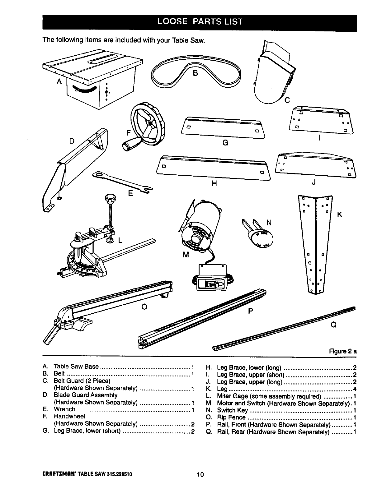
The following items are included with your Table Saw.
A, Table Saw Base .................................................... 1
B. Belt ....................................................................... 1
C. Belt Guard (2 Piece)
(Hardware Shown Separately) ............................. 1
D. Blade Guard Assembly
(Hardware Shown Separately) ............................. 1
E. Wrench ................................................................. 1
F. Handwheel
(Hardware Shown Separately) ............................. 2
G. Leg Brace, lower (short) ....................................... 2
rRBFTSMAN"TABLESAW315.228510 I0
Figure 2 a
H. Leg Brace, lower (long) ........................................ 2
I. Leg Brace, upper (short)....................................... 2
J. Leg Brace, upper (long) ........................................ 2
K. Leg ........................................................................ 4
L. Miter Gage (some assembly required) ................. 1
M. Motor and Switch (Hardware Shown Separately). 1
N. Switch Key ............................................................ 1
O. Rip Fence ............................................................. 1
P. Rail, Front (Hardware Shown Separately) ............ 1
Q. Rail, Rear (Hardware Shown Separately) ............ 1
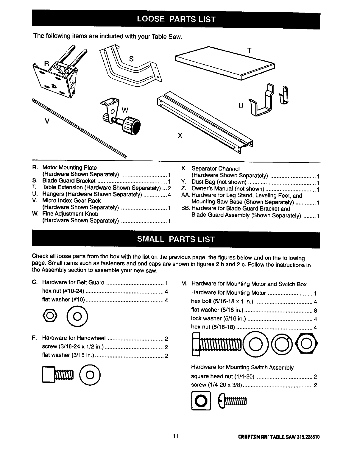
The following items are included with your Table Saw.
T
X
R. Motor Mounting Plate
(Hardware Shown Separately) ............................. 1
S. Blade Guard Bracket ............................................ 1
T. Table Extension (Hardware Shown Separately) ,..2
U. Hangers (Hardware Shown Separately) ............... 4
V. Micro Index Gear Rack
(Hardware Shown Separately) ............................. 1
W. Fine Adjustment Knob
X. Separator Channel
(Hardware Shown Separately) ............................. 1
Y, Dust Bag (not shown) ........................................... 1
Z. Owner's Manual (not shown) ................................ 1
AA. Hardware for Leg Stand, Leveling Feet, and
Mounting Saw Base (Shown Separately) ............. 1
BB. Hardware for Blade Guard Bracket and
Blade Guard Assembly (Shown Separately) ........ 1
(Hardware Shown Separately) ............................. 1
Check all loose parts from the box with the list on the previous page, the figures below and on the following
page. Small items such as fasteners and end caps are shown in figures 2 b and 2 c. Follow the instructions in
the Assembly section to assemble your new saw.
C. Hardware for Belt Guard .................................... 1
hex nut (#10-24) ................................................. 4
flat washer (#10) ................................................. 4
M,
Hardware for Mounting Motor and Switch Box
Hardware for Mounting Motor ............................ 1
hex bolt (5/16-18 x 1 in.) .................................... 4
flat washer (5/16 in.) ........................................... 8
lock washer (5/16 in.) ......................................... 4
hex nut (5/16-18) ................................................ 4
F. Hardware for Handwheel ................................... 2
screw (3/16-24 x 1/2 in.) ..................................... 2
flat washer (3/16 in.) ........................................... 2
Hardware for Mounting Switch Assembly
square head nut (1/4-20) .................................... 2
screw (1/4-20 x 3/8) ............................................ 2
11 I:RRFT$14RN"TABLESAW315.228510
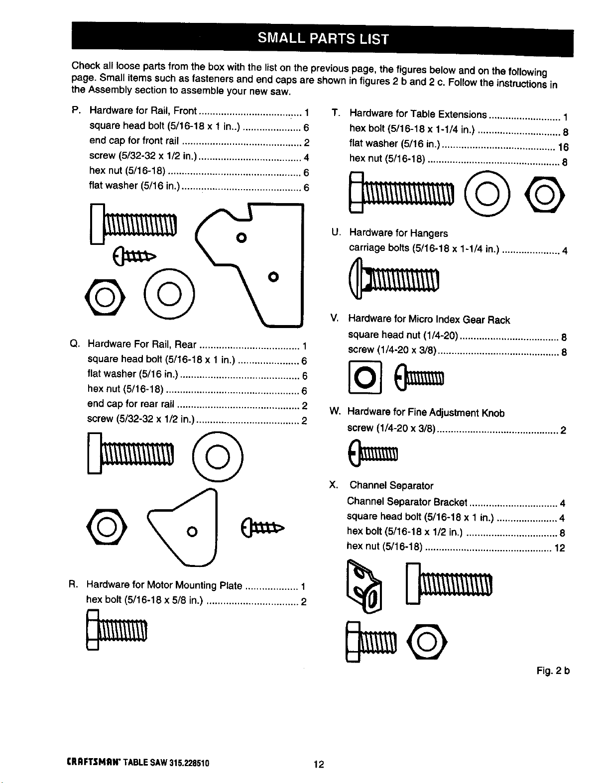
Check all loose parts from the box with the list on the previous page, the figures below and on the following
page. Small items such as fasteners and end caps are shown in figures 2 b and 2 c. Follow the instructions in
the Assembly section to assemble your new saw.
P. Hardware for Rail, Front ..................................... 1
square head bolt (5/16-18 x 1 in..) ..................... 6
end cap for front rail ........................................... 2
screw (5/32-32 x 1/2 in.) ..................................... 4
hex nut (5/16-18) ................................................ 6
flat washer (5/16 in.)........................................... 6
O
O
o©
Q. Hardware For Rail, Rear .................................... 1
square head bolt (5/16-18 x 1in.) ...................... 6
flat washer (5/16 in.)........................................... 6
hex nut (5/16-18) ................................................ 6
end cap for rear rail ............................................ 2
screw (5/32-32 x 1/2 in.)..................................... 2
T.
Hardware for Table Extensions .......................... 1
hex bolt (5/16-16 x 1-1/4 in.) .............................. 8
flat washer (5/16 in.) ......................................... 16
hex nut (5/16-18) ................................................ 8
U.
Hardware for Hangers
carriage bolts (5/16-18 x 1-1/4 in.) ..................... 4
V,
Hardware for Micro Index Gear Rack
square head nut (1/4-20) .................................... 8
screw (1/4-20 x 3/8) ............................................ 8
W,
Hardware for Fine Adjustment Knob
screw (1/4-20 x 3/8) ............................................ 2
©
R,
Hardware for Motor Mounting Plate ................... 1
hex bolt (5/16-18 x 5/8 in.) ................................. 2
CRRFTSNRW TABLESAW 315.228510 12
O
X.
Channel Separator
Channel Separator Bracket ................................ 4
square head bolt (5/16-18 x 1 in.) ...................... 4
hex bolt (5/16-18 x 1/2 in.) ................................. 8
hex nut (5/16-18) .............................................. 12
Fig. 2 b
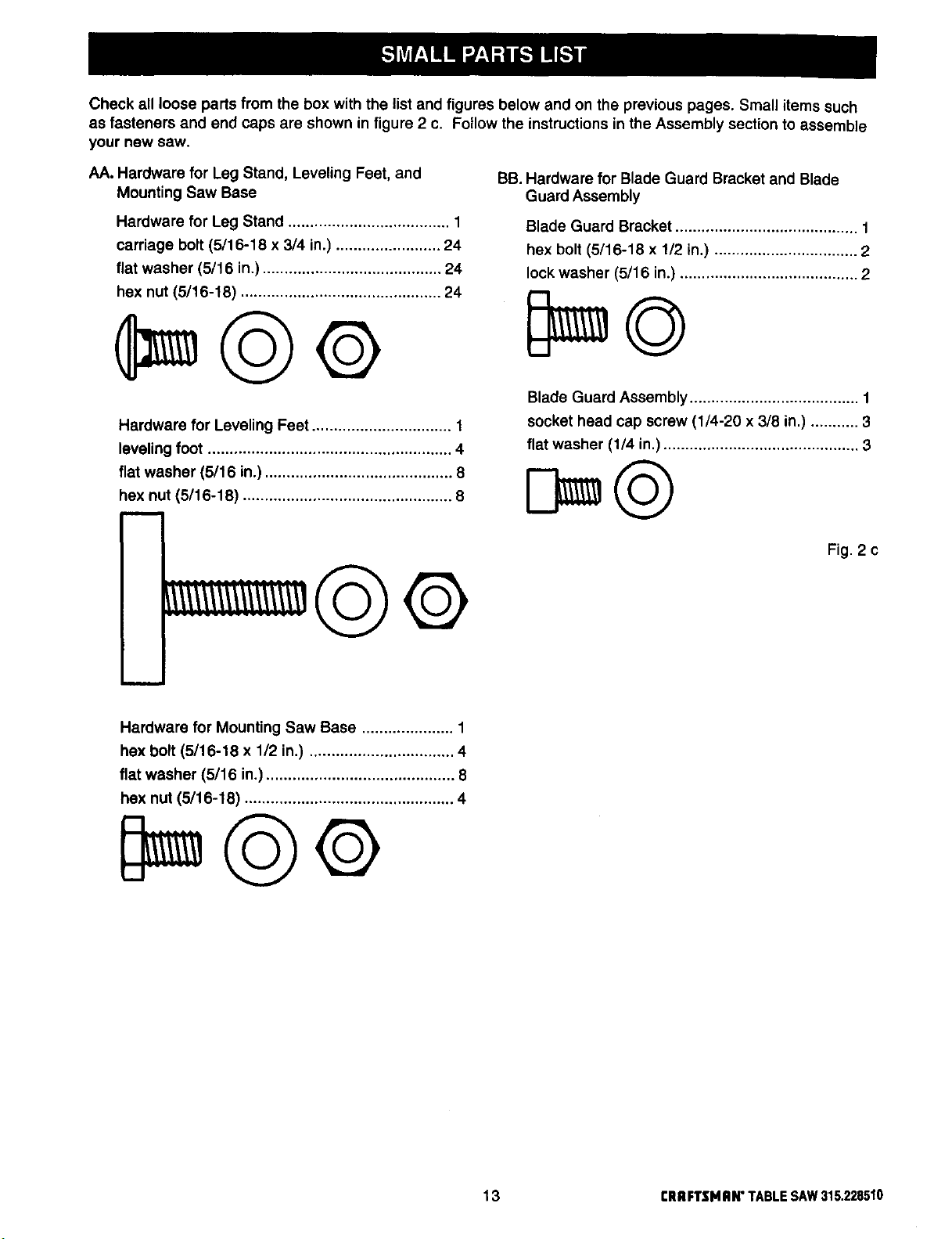
Check all loose parts from the box with the list and figures below and on the previous pages. Small items such
as fasteners and end caps are shown in figure 2 c. Follow the instructions in the Assembly section to assemble
your new saw.
AA. Hardware for Leg Stand, Leveling Feet, and
Mounting Saw Base
Hardware for Leg Stand ..................................... 1
carriage bolt (5/16-18 x 3/4 in.) ........................ 24
flat washer (5/16 in.) ......................................... 24
hex nut (5/16-18) .............................................. 24
Hardware for Leveling Feet ................................ 1
leveling foot ........................................................ 4
flat washer (5/16 in.) ........................................... 8
hex nut (5/16-18) ................................................ 8
©©
BB. Hardware for Blade Guard Bracket and Blade
Guard Assembly
Blade Guard Bracket .......................................... 1
hex bolt (5/16-18 x 1/2 in.) ................................. 2
lock washer (5/16 in.) ......................................... 2
Blade Guard Assembly ....................................... f
socket head cap screw (1/4-20 x 3/8 in.) ........... 3
flat washer (1/4 in.) ............................................. 3
Fig. 2 c
Hardware for Mounting Saw Base ..................... 1
hex bolt (5/16-18 x 1/2 in.) ................................. 4
flat washer (5/16 in.) ........................................... 8
hex nut (5/16-18) ................................................ 4
13 CRRFTSHAN"TABLESAW315.228510
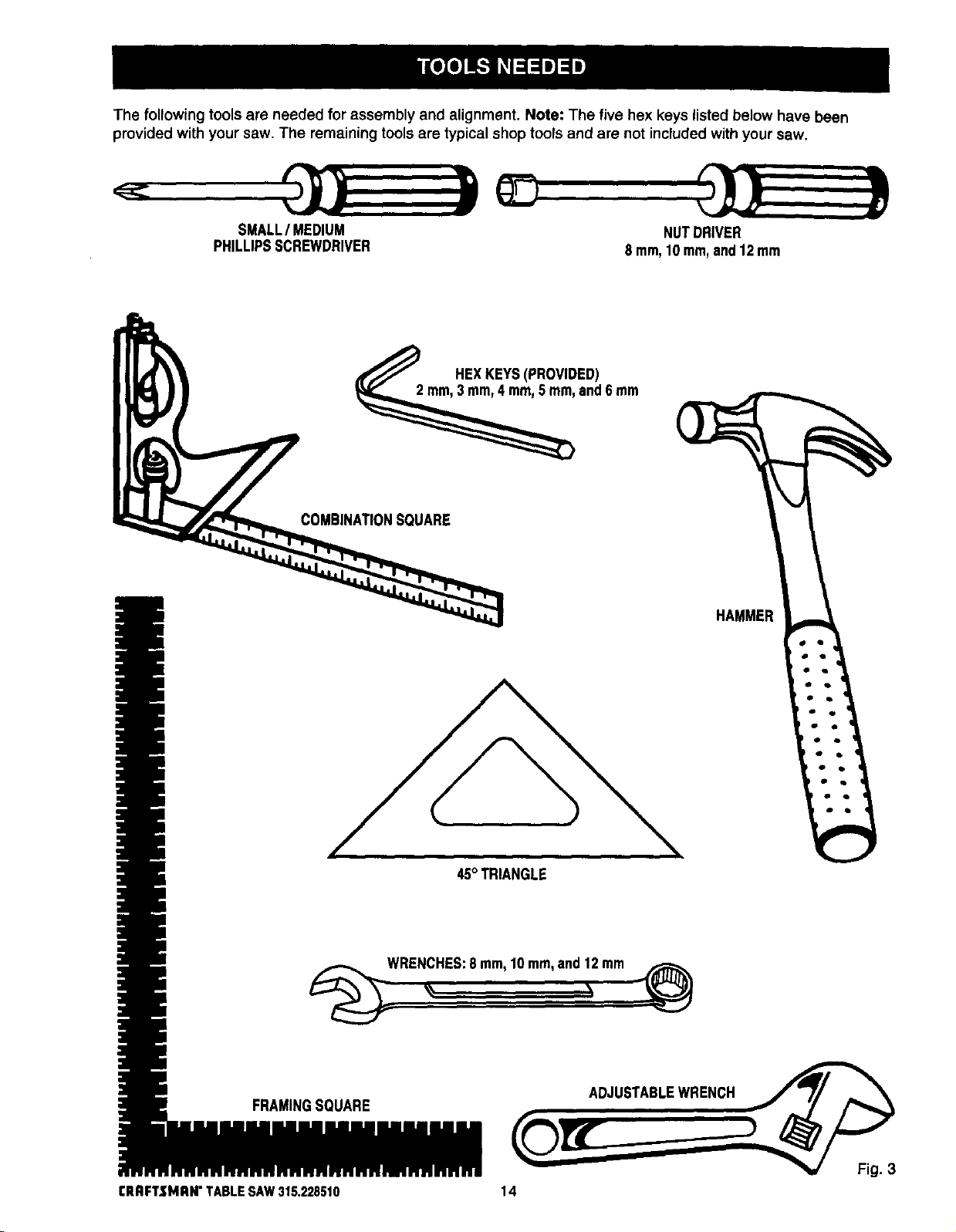
Thefollowing tools are needed for assembly and alignment. Note: The five hex keys listed below have been
provided with your saw. The remaining tools are typical shop tools and are not included with your saw.
SMALL/ MEDIUM
PHILLIPSSCREWDRIVER
COMBINA_ONSQUARE
NUTDRIVER
8 mm,10 mm,and12 mm
HEXKEYS(PROVIDED)
and6 mm
HAMMER
FRAMINGSQUARE
ERnFTSMRH" TABLESAW315.228510
45° TRIANGLE
WRENCHES:8mm,10 mm,and 12mm
ADJUSTABLEWRENCH
14
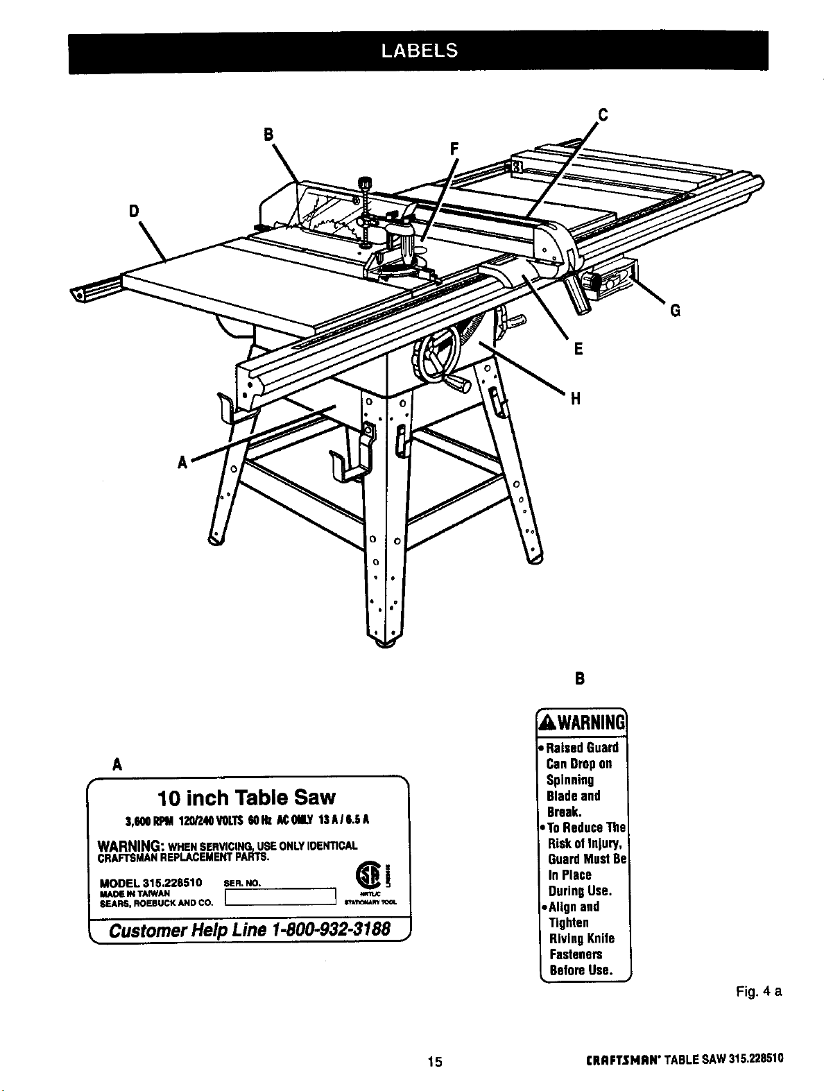
C
B
F
D
G
E
H
A
10 inch Table Saw
3,100RPM120/240VOLTSNI_ AC01B.Y13AII.!IA
WARNING: WHEN SERVICING,USE ONLYIDENTICAL
CRAFTSMANREPLACEMENTPARTS,
MODEL 315.228510 SEFI.NO. _i
MADE IN TAMAN I I
SEARS, ROEBUCK AND CO.
• Customer Help Line 1-800.932-3188 •
B
AWARNING
, RaisedGuard
CanDropon
Spinning
Bladeand
Break.
,,ToReduceThe
RiskofInjury,
GuardMustBe
In Place
DuringUse.
,Alignand
Tighten
RivingKnife
Fasteners
BeforeUse.
Fig. 4 a
15 CRRFTSMRN" TABLESAW 315.228510
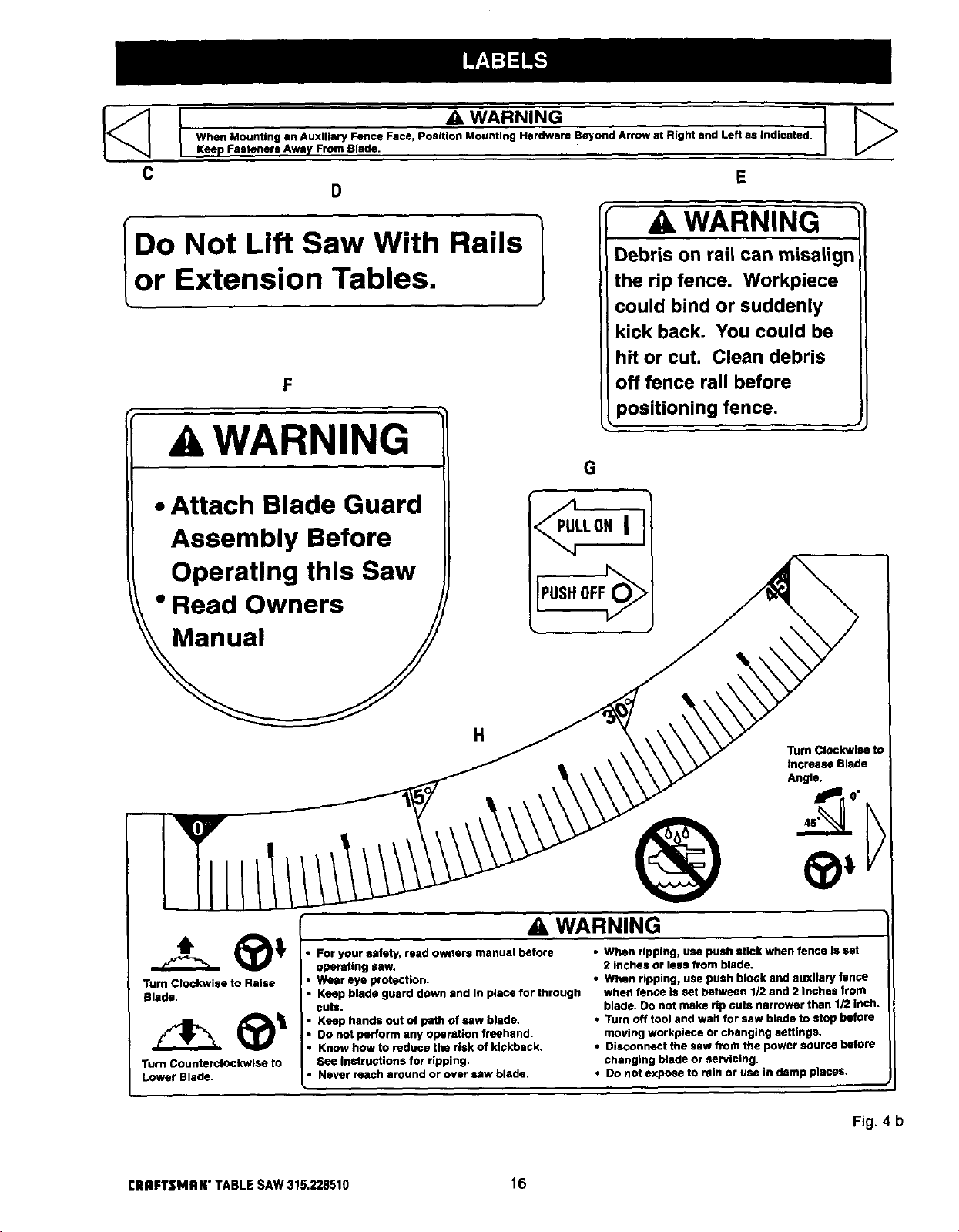
When Mounting an Auxiliary Fence Face, Position Mounting Hardware Beyond Arrow at Right and Left as indicated.
Keep Fasteners Away From Blade. I
C
D
A WARNING
WARNING
Do Not Li.ftSaw With Rails
or Extension Tables.
F
A WARNING
• Attach Blade Guard
Assembly Before
Operating this Saw
_" Read Owners /
Debris on rail can misalign
the rip fence. Workpiece
could bind or suddenly
kick back. You could be
hit or cut. Clean debris
off fence rail before
positioning fence.
G
Turn Clockwise to Raise
Blade,
Turn Counterclockwise to
Lower Blade.
H
For your safety, read owners manuel before
operating saw.
Wear eye protection.
Keep blade guard down and In place for through
cuts.
Keep hands out of path of saw blade.
Do not perform any operation freehand.
Know how to reduce the risk of kickback.
See instructions for ripping.
• Never reach around or over saw blade.
Turn Clockwlsa to
Increase Blade
Angle.
WARNING
• When ripping, use push stick when fence is set
2 Inches or less from blade.
• When ripping, usa push block and auxllary fence
when fence is set between 1/2 end 2 Inches from
blade. Do not make rip cuts narrower than 1/2 Inch.
• Turn off tool and wait for saw blade to stop before
moving workplece or changing settings.
• Disconnect the saw from the power source before
changing blade or servicing.
• Do not expose to rain or use in damp places.
Fig. 4 b
[RRFTSMRW TABLE SAW315.228510 16
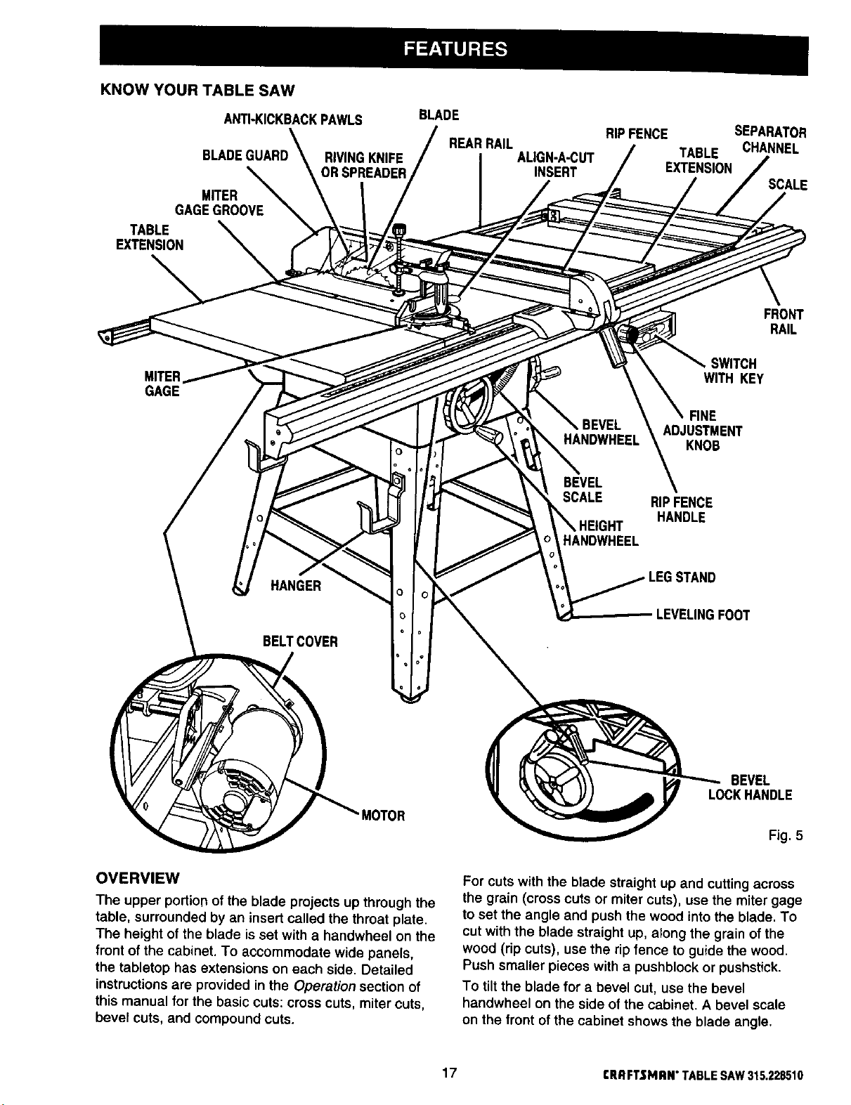
KNOW YOUR TABLE SAW
ANTI-KICKBACKPAWLS
BLAD
MITER _
GAGEGROOVE
TABLE
EXTENSION
RIVINGKNIFE
ORSPREADER
BLADE
REARRAIL
ALIGN-A-CUT
INSERT
RIP FENCE SEPARATOR
TABLE CHANNEL
EXTENSION
SCALE
FRONT
RAIL
MITER
GAGE
HANGER
BELTCOVER
WITH KEY
FINE
HANDWHEEL
ADJUSTMENT
KNOB
BEVEL
SCALE RIP FENCE
HEIGHT
HANDLE
HANDWHEEL
LEVELINGFOOT
SWITCH
MOTOR
OVERVIEW
The upper portion of the blade projects up through the
table, surrounded by an insert called the throat plate.
The height of the blade is set with a handwheel on the
front of the cabinet. To accommodate wide panels,
the tabletop has extensions on each side. Detailed
instructions are provided in the Operation section of
this manual for the basic cuts: cross cuts, miter cuts,
bevel cuts, and compound cuts.
BEVEL
LOCKHANDLE
Fig. 5
For cuts with the blade straight up and cutting across
the grain (cross cuts or miter cuts), use the miter gage
to set the angle and push the wood intothe blade. To
cut with the blade straight up, along the grain of the
wood (rip cuts), use the rip fence to guide the wood.
Push smaller pieces with a pushblock or pushstick.
To tilt the blade for a bevel cut, use the bevel
handwheel on the side of the cabinet. A bevel scale
on the front of the cabinet shows the blade angle.
17 CRRFTSMRN"TABLESAW315.228510
Inside the cabinet, adjustable positive stops control
the degree of tilt.
Use the miter gage with a bevel cross cut (compound
cut) and the rip fence with a bevel rip cut. Other cuts
require special attachments, which have detailed
instructions to reduce risk of injury and ensure the
best performance from your new saw.
Before attempting to use your saw, familiarize yourself
with all operating features and safety requirements of
your Sears Craftsman table saw. The saw's features
are described below.
ALIGN-A-CUT INSERT - A plastic insert on which
marks may be made to indicate the location of the
sawcut on the workpiece.
ANTI-KICKBACK PAWLS - Kickback is a hazard in
which the workpiece is thrown back toward the
operator. The toothed pawls are designed to snag the
workpiece to prevent or reduce injury should kickback
Occur.
BEVEL HANDWHEEL - This handwheel, on the right
side of the cabinet, tilts the blade for a bevel cut.
BEVEL SCALE - The easy-to-read scale on the front
of the workstand shows the exact blade angle.
BLADE -This saw is provided with a Craftsman 40
tooth, 10 in. carbide tipped blade. The blade is
adjusted with bevel and height handwheels on the
cabinet. Bevel angles are locked with a handle below
the front rail.
_1, WARNING: Be sure to use only blades rated for
at least 5,000 rpm and recommended for use on
this saw, Check with your nearest Sears retail
store.
BLADE COVER - The internal cover contains sawdust
so it can be directed into the sawdust bag.
BLADE GUARD - Always keep the guard down over
the blade for through-sawing cuts.
BEVEL LOCK HANDLE - This handle, placed just
under the worktable surface on the front of the cabi-
net, locks the angle setting of the blade. Be sure the
handle is hanging straight down before tilting the
blade. If it is not straight down, it may jam and bend
the locking bolt.
DUAL VOLTAGE - Your table saw can be set up to
operate at 120 voltage or at 240. Use extreme caution
when changing the voltage.
DUST BAG - Saw dust can be directed into this
detachable bag or into a wet/dry vacuum.
HEIGHT HANDWHEEL - Use this handwheel to lower
and raise the blade for adjustments or replacement. It
is located on the front of the cabinet.
MICRO-INDEX - A rip fence gear and track that
provides precise indexing.
MITER GAGE - This gage aligns the wood for a
crosscut. The easy-to-read indicator shows the exact
angle for a miter cut, with positive stops at 90" and
45".
MITER GAGE GROOVES - The miter gage rides in
these grooves on either side of the blade.
MITER GAGE HOLD-DOWN - A clamp assembly that
fits onto the miter gage to provide additional stability.
MITER GAGE KNOB - Located on the miter gage,
this knob locks in the cutting angle after selection.
MOTOR (13/6,5 AMP) -The powerful induction motor
is 3HP, with capacitor start and V-belt drive, and is
housed in a sturdy steel base.
OVERLOAD PROTECTOR - This device switches off
the saw if it overheats. See the Operation section.
RAILS - Front and rear rails provide support for large
workpieces and the rip fence.
RIP FENCE - A sturdy metal fence guides the
workpiece and is secured with the ripfence handle.
Grooves run along the top and sides of the ripfence
for use with optional clamps and accessories.
RIP FENCE FINE ADJUSTMENT KNOB - The knob
on the front of the np fence makes fine adjustments to
the desired measurement forprecise cutting. Push in
the knob and turn to position the rip fence.
RIP FENCE HANDLE - The handle on the front of the
rip fence releases the rip fence or locks it in place.
RIVING KNIFE OR SPREADER - Located directly
behind the blade, it keeps cut edges from bindingand
supports the blade guard.
SCALE - Found on the front rail, the easy-to-read
scale provides precise measurements in rip cuts.
SWITCH WITH KEY - Your table saw has an easy
access power switch located below the front rail. The
yellow switch key must be removed from the hard-
ware bag and inserted intothe switch before saw can
be operated. To lock the switch in the OFF position,
remove the switch key from the switch. Place the key
in a location that is inaccessible to children and others
not qualified to use the tool.
TABLE EXTENSIONS - Removable cast iron exten-
sions, 12 in. by 27 in., support larger workpieces.
CRAFTSMAN"TABLESAW315.228510 18
Assembly is best done in the area where the saw will be used. When you remove the table saw base, loose
parts, and hardware from the packing materials, check all items with the loose parts list and drawing. If you are
unsure about the description of any part, refer to the drawing. If any parts are missing, delay assembling until
you have obtained the missing part(s).
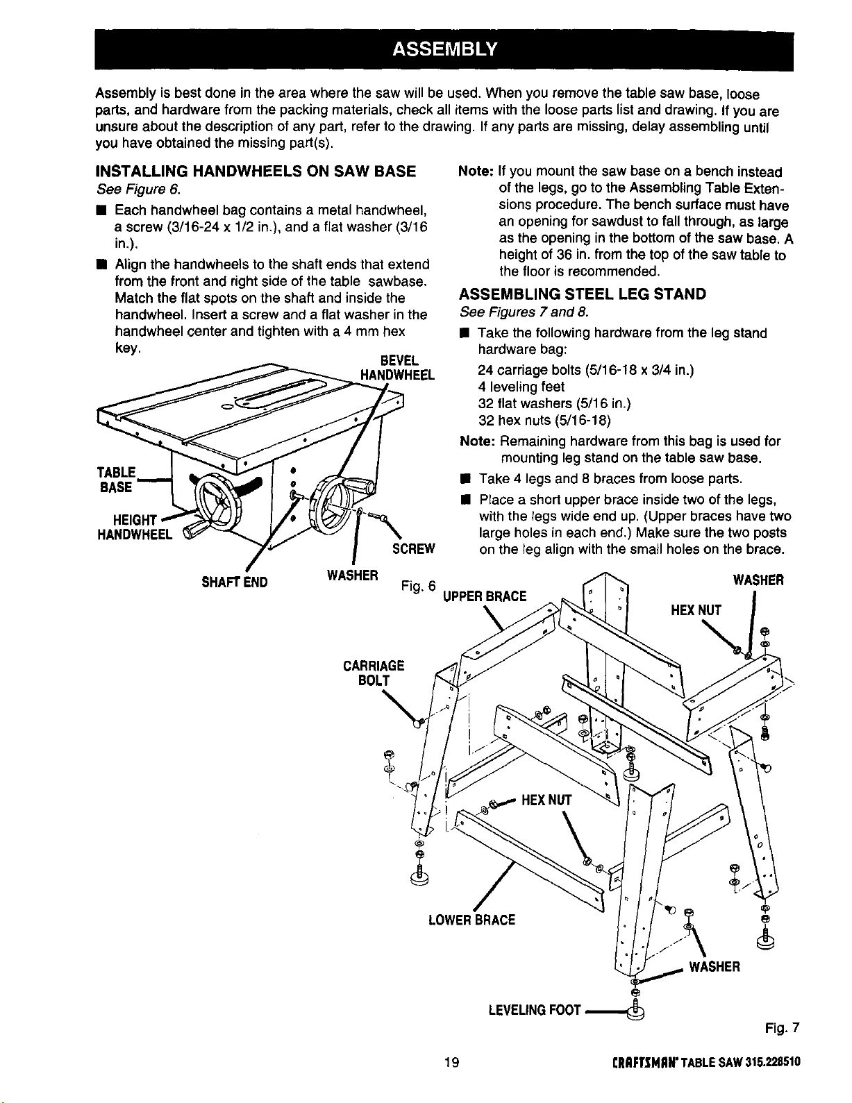
INSTALLING HANDWHEELS ON SAW BASE
See Figure6.
[] Each handwheel bag contains a metal handwheel,
a screw (3/16-24 x 1/2 in.), and a flat washer (3/16
in.),
[] Align the handwheels to the shaft ends that extend
from the front and right side of the table sawbase.
Match the flat spots on the shaft and inside the
handwheel. Insert a screw and a flat washer in the
handwheel center and tighten with a 4 mm hex
key.
BEVEL
HANDWHEEL
TABLE
BABE
HANDWHEEL
SCREW
Note: If you mount the saw base on a bench instead
of the legs, go to the Assembling Table Exten-
sions procedure. The bench surface must have
an opening for sawdust to fall through, as large
as the opening in the bottom of the saw base. A
height of 36 in. from the top of the saw table to
the floor is recommended.
ASSEMBLING STEEL LEG STAND
See Figures7and8.
[] Take the following hardware from the leg stand
hardware bag:
24 carriage bolts (5/16-18 x 3/4 in.)
4 leveling feet
32 flat washers (5/16 in.)
32 hex nuts(5/16-18)
Note: Remaining hardware from this bag is used for
mounting leg stand on the table saw base.
[] Take 4 legs and 8 braces from loose parts.
[] Place a short upper brace inside two of the legs,
with the legs wide end up. (Upper braces have two
large holes in each end.) Make sure the two posts
on the leg align with the small holes on the brace.
SHAFTEND
WASHER
CARRIAGE
BOLT
Fig. 6 UPPERBRACE
WASHER
HEXNUT
LOWERBRACE
WASHER
e
LEVELING FOOT
Fig. 7
19 rRaFTSNRN'TABLESAW315.228510
• Align the two large holes on the brace and the
legs. Insert the carriage bolts. Add flat washers
and hex nuts and hand tighten. Repeat for the
other short upper brace. These are the front and
back sets.
• For the side sets, installa long upper brace on two
legs. Add hardware and finger tighten. Repeat for
the other long upper brace.
• Use the same steps to install the lower braces.
Tighten all hex nuts with a 12 rnm wrench.
• Place a hex nut and flat washer on each leveling
foot. Install the leveling feet from the bottom of
each leg with the bolts pointing up. Cap with the
remaining flat washers and hex nuts but do not
tighten.
• Move the leg set to desired location. Adjust the
leveling feet with a 12 mm wrench, then tighten the
top hex nut.
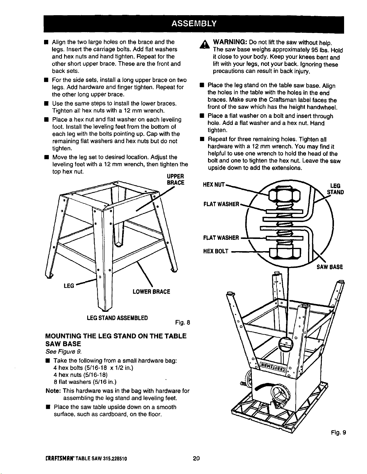
UPPER
BRACE
_I, WARNING: Do not lift the saw without help.
The saw base weighs approximately 95 Ibs. Hold
itclose to your body. Keep your knees bent and
liftwith your legs, not your back. Ignoring these
precautions can result in back injury.
• Place the leg stand on the table saw base. Align
the holes in the table with the holes in the end
braces. Make sure the Craftsman label faces the
front of the saw which has the height handwheel.
• Place a flat washer on a bolt and insert through
hole, Add a flat washer and a hex nut. Hand
tighten.
• Repeat for three remaining holes. Tighten all
hardware with a 12 mm wrench. You may find it
helpful to use one wrench to hold the head of the
bolt and one to tighten the hex nut. Leave the saw
upside down to add the extensions.
HEXNI LEG
STAND
LEG
LOWERBRACE
LEGSTANDASSEMBLED
Fig. 8
MOUNTING THE LEG STAND ON THE TABLE
SAW BASE
See Figure 9.
• Take the following from a small hardware bag:
4 hex bolts (5/16-18 x 1/2 in.)
4 hex nuts (5/16-18)
8 flat washers (5/16 in.)
Note: This hardware was in the bag with hardware for
assembling the leg stand and leveling feet.
• Place the saw table upside down on a smooth
surface, such as cardboard, on the floor.
FLATWASHER
HEXBOLT
SAWBASE
I:RRFTSMR#"TABLESAW315.228510 20
Fig. 9
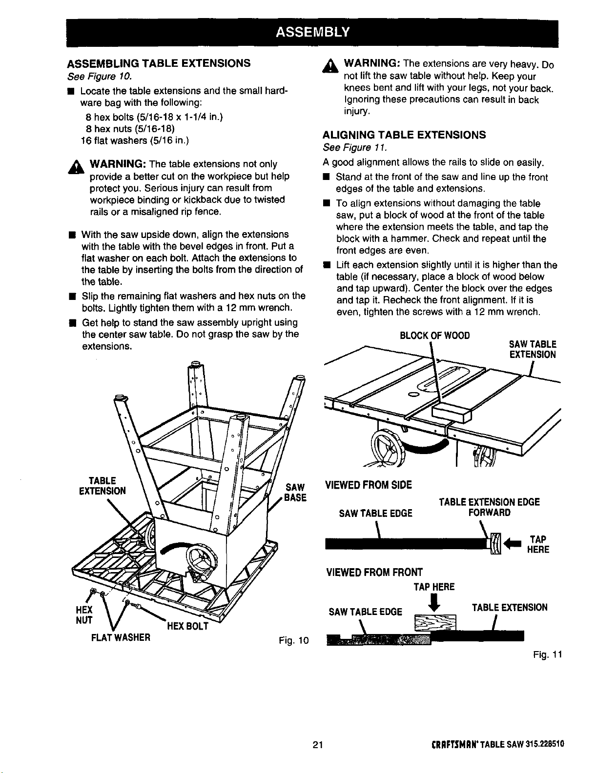
ASSEMBLING TABLE EXTENSIONS
See Figure 10.
• Locate the table extensions and the small hard-
ware bag with the following:
8 hex bolts (5/16-18 x 1-1/4 in.
8 hex nuts (5/16-18)
16 flat washers (5/16 in.)
_1, WARNING: The table extensions not only
provide a better cut on the workpiece but help
protect you. Serious injury can result from
workpiece binding or kickback due to twisted
rails or a misaligned ripfence.
• With the saw upside down, align the extensions
with the table with the bevel edges in front. Put a
flat washer on each bolt. Attach the extensions to
the table by inserting the bolts from the direction of
the table.
• Slip the remaining flat washers and hex nuts on the
bolts. Lightly tighten them with a 12 mm wrench.
• Get help to stand the saw assembly upright using
the center saw table. Do not grasp the saw by the
extensions.
_1, WARNING: The extensions are very heavy. Do
not lift the saw table without help. Keep your
knees bent and liftwith your legs, notyour back.
Ignoring these precautions can result in back
injury.
ALIGNING TABLE EXTENSIONS
See Figure 11.
A good alignment allows the railsto slide on easily.
• Stand at the front of the saw and line up the front
edges of the table and extensions.
• To align extensions without damaging the table
saw, put a block of wood at the front of the table
where the extension meets the table, and tap the
block with a hammer. Check and repeat until the
front edges are even.
• Lift each extension slightlyuntil it is higher than the
table (if necessary, place a blockof wood below
and tap upward). Center the block over the edges
and tap it. Recheck the front alignment. If it is
even, tighten the screws with a 12 mm wrench.
BLOCKOFWOOD
SAWTABLE
EXTENSION
TABLE
EXTENSION
HEX
NUT
FLATWASHER
HEXBOLT
SAW
,BASE
Fig. 10
VIEWED FROM SIDE
TABLEEXTENSIONEDGE
SAWTABLEEDGE
VIEWED FROM FRONT
TAPHERE
SAWTABLEEDGE !
21 CRRFTSMRN*TABLESAW315.228510
FORWARD
_lm TAP
HERE
TABLEEXTENSION
Fig. 11
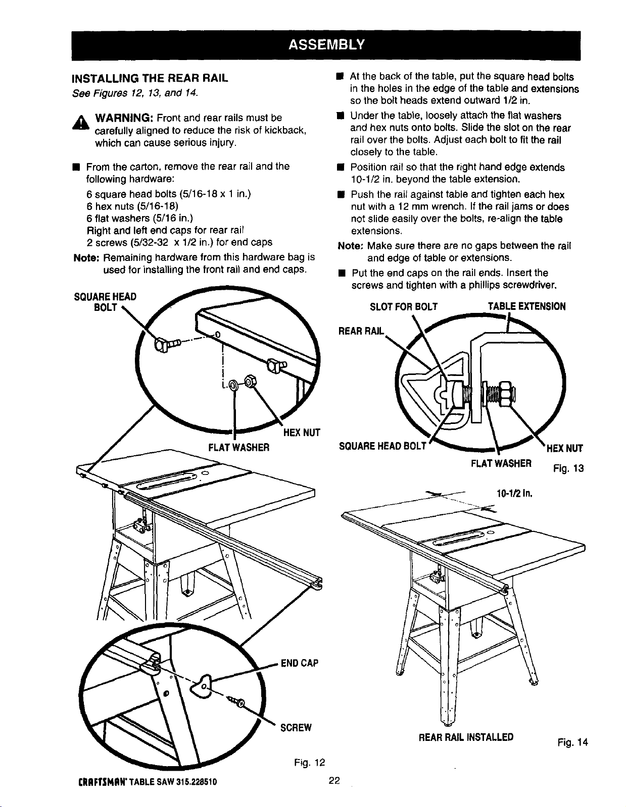
INSTALLING THE REAR RAIL
See Figures 12, 13, and 14.
,_ WARNING: Front and rear rails must be
carefully aligned to reduce the risk of kickback,
which can cause serious injury.
• From the carton, remove the rear rail and the
following hardware:
6 square head bolts (5/16-18 x 1 in.)
6 hex nuts (5/16-18)
6 flat washers (5/16 in.)
Right and left end caps for rear rail
2 screws (5/32-32 x 1/2 in.) for end caps
Note: Remaining hardware from this hardware bag is
used for installing the front rail and end caps.
SQUAREHEAD
• At the back of the table, put the square head bolts
in the holes in the edge of the table and extensions
so the bolt heads extend outward 1/2 in.
• Under the table, loosely attach the flat washers
and hex nuts onto bolts. Slide the slot on the rear
rail over the bolts. Adjust each bolt to fit the rail
closely to the table.
• Position rail so that the right hand edge extends
10-1/2 in. beyond the table extension.
• Push the rail against table and tighten each hex
nut with a 12 mm wrench. If the rail jams or does
not slide easily over the bolts, re-align the table
extensions.
Note: Make sure there are no gaps between the rail
and edge of table or extensions.
• Put the end caps on the rail ends. Insert the
screws and tighten with a phillips screwdriver.
SLOTFOR BOLT
REARRAIL
TABLEEXTENSION
\
FLATWASHER
HEXNUT
!NDCAP
SQUAREHEADBOLT
FLATWASHER
1_1_1n.
HEXNUT
Fig. 13
SCREW
Fig. 12
CRAFTSNAN'TABLE SAW315.228510 22
REARRAILINSTALLED
Fig. 14
 Loading...