

Craftsman 315218291 Owner’s Manual

OPERATOR' MAN
RRFf$1ulI:IN
10 in, TABLE SAW
Model No.
315.218291
AL
o
A
WARNING: To reduce the risk of injury,the
user must read and understand the operator's
manual before using this product.
Customer Help Line: 1-800-932-3188
Product distributed in the United States by Sears Brands Management Corporation
Hoffman Estates, IL 60179
Visit the Craftsman web page: www.sears.com
988000-067
10-5-10 (REV:04)
Save this manual for future reference
C

[] Introduction ...................................................................................................................................................................... 2
[] Warranty ........................................................................................................................................................................... 2
[] General Safety Rules ..................................................................................................................................................... 3-4
[] Specific Safety Rules ..................................................................................................................................................... 4-5
[] Symbols ......................................................................................................................................................................... 6-7
[] Electrical ............................................................................................................................................................................ 8
[] Glossary of Terms .............................................................................................................................................................. 9
[] Features ..................................................................................................................................................................... 10-13
[] Tools Needed .................................................................................................................................................................. 13
[] Loose Parts ............................................................................................................................................................... 14-15
[] Assembly ................................................................................................................................................................... 16-25
[] Operation ................................................................................................................................................................... 26-43
[] Adjustments ............................................................................................................................................................... 44-47
[] Maintenance .................................................................................................................................................................... 48
[] Troubleshooting ......................................................................................................................................................... 49-50
[] Illustrated Parts List ................................................................................................................................................... 51-65
[] Parts Ordering/Service ...................................................................................................................................... Back Page
This tool has many features for making its use more pleasant and enjoyable. Safety, performance, and dependability
have been given top priority in the design of this product making it easy to maintain and operate.
ONE YEAR FULL WARRANTY Oit (::;FIAFTSMA11TOOL
If this Craftsman tool fails due to a defect in material or workmanship within one year from the date of purchase. (::;all
1-800-4-MY-HOME ® to arrange for free repair. If this tool is used for commercial or rental purposes, this warranty will
apply for only ninety days from the date of purchase. This warranty applies only while this product is in the United States.
This warranty gives you specific legal rights, and you may also have other rights which vary from state to state.
Sears, Roebuck and Co., Dept. 817WA, Hoffman Estates, IL 60179
_l_ WARNING: Read and understand all instruc-
tions. Failure to follow all instructions listed below,
may result in electric shock, fire and/or serious
personal injury.
READ ALL INSTRUCTIONS
[] KNOW YOUR POWER TOOL. Read the operator's
manual carefully. Learn the saw's applications and
limitations as well as the specific potential hazards
related to this tool.
[] GUARD AGAINST ELECTRICAL SHOCK BY
PREVENTING BODY CONTACT WITH GROUNDED
SURFACES. For example, pipes, radiators, ranges,
refrigerator enclosures.
[] KEEP GUARDS IN PLACE and in good working order.
[] REMOVE ADJUSTING KEYS AND WRENCHES.
Form habit of checking to see that keys and adjusting
wrenches are removed from tool before turning it on.
[] KEEP WORK AREA CLEAN. Cluttered areas and
benches invite accidents. DO NOT leave tools or
pieces of wood on the saw while it is in operation.
[] DO NOT USE IN DANGEROUS ENVIRONMENTS.
Do not use power tools in damp or wet locations or
expose to rain. Keep the work area well lit.
[] KEEP CHILDREN AND VISITORS AWAY. All visitors
should wear safety glasses and be kept a safe
distance from work area. Do not let visitors contact
tool or extension cord while operating.
[] MAKE WORKSHOP CHILDPROOF with padlocks and
master switches, or by removing starter keys.
[] DON'T FORCE TOOL. It will do the job better and
safer at the feed rate for which it was designed.
[] USE RIGHT TOOL. Don't force the tool or attachment
to do ajob it was not designed for. Don't use it for a
purpose not intended.
[] USE THE PROPER EXTENSION CORD. Make sure
your extension cord is in good condition. Use only a
cord heavy enough to carry the current your product
will draw. An undersized cord will cause a drop in line
voltage resulting in loss of power and overheating. A
wire gauge size (A.W.G.) of at least 14 is recommended
for an extension cord 25 feet or less in length. If in
doubt, use the next heavier gauge. The smaller the
gauge number, the heavier the cord.
[] DRESS PROPERLY. Do not wear loose clothing,
gloves, neckties, or jewelry. They can get caught
and draw you into moving parts. Rubber gloves and
nonskid footwear are recommended when working
outdoors. Also wear protective hair covering to contain
long hair.
[] ALWAYS WEAR SAFETY GLASSES WiTH SIDE
SHIELDS. Everyday eyeglasses have only impact-
resistant lenses, they are NOT safety glasses.
[] SECURE WORK. Use clamps or a vise to hold work
when practical. It's safer than using your hand and
frees both hands to operate tool.
[] DON'T OVERREACH. Keep proper footing and
balance at all times.
[] MAINTAIN TOOLS WITH CARE. Keep tools sharp
and clean for better and safer performance. Follow
instructions for lubricating and changing accessories.
[] DISCONNECT TOOLS. When not in use, before
servicing, or when changing attachments, blades, bits,
cutters, etc., all tools should be disconnected.
[] AVOID ACCIDENTAL STARTING. Be sure switch is off
when plugging in any tool.
[] USE RECOMMENDED ACCESSORIES. Consult the
operator's manual for recommended accessories. The
use of improper accessories may risk injury.
[] NEVER STAND ON TOOL. Serious injury could
occur if the tool is tipped or if the cutting tool is
unintentionally contacted.
[] CHECK DAMAGED PARTS. Before further use of
the tool, a guard or other part that is damaged should
be carefully checked to determine that it will operate
properly and perform its intended function. Check for
alignment of moving parts, binding of moving parts,
breakage of parts, mounting and any other conditions
that may affect its operation. A guard or other part that
is damaged must be properly repaired or replaced by
an authorized service center to avoid risk of personal
injury.
[] USE THE RIGHT DIRECTION OF FEED. Feed work
into a blade or cutter against the direction of rotation of
blade or cutter only.
[] NEVER LEAVE TOOL RUNNING UNATTENDED.
TURN THE POWER OFF. Don't leave tool until it
comes to a complete stop.
[] PROTECT YOUR LUNGS. Wear a face or dust mask if
the cutting operation is dusty.
[] PROTECT YOUR HEARING. Wear hearing protection
during extended periods of operation.
[] DO NOT ABUSE CORD. Never yank cord to
disconnect from receptacle. Keep cord away from
heat, oil, and sharp edges.
[] WHEN OPERATING A POWER TOOL OUTSIDE, USE
AN OUTDOOR EXTENSION CORD MARKED "W-A"
OR "W". These cords are rated for outdoor use and
reduce the risk of electric shock.
[] KEEP BLADES CLEAN, SHARP, AND WITH
SUFFICIENT SET. Sharp blades minimize stalling
and kickback.
[] KEEP HANDS AWAY FROM CUTTING AREA. Keep
hands away from blades. Do not reach underneath
work or around or over the blade while blade is
rotating. Do not attempt to remove cut material when
blade is moving.

[] BLADE COASTS AFTER BEING TURNED OFF.
[] NEVER USE iN AN EXPLOSIVE ATMOSPHERE.
Normal sparking of the motor could ignite fumes.
[] INSPECT TOOL CORDS PERIODICALLY. If damaged,
have repaired by a qualified service technician at
an authorized service facility. The conductor with
insulation having an outer surface that is green with
or without yellow stripes is the equipment-grounding
conductor. If repair or replacement of the electric cord
or plug is necessary, do not connect the equipment-
grounding conductor to a live terminal. Repair or
replace a damaged or worn cord immediately. Stay
constantly aware of cord location and keep it well
away from the rotating blade.
[] INSPECT EXTENSION CORDS PERIODICALLY and
replace if damaged.
[] GROUND ALL TOOLS. If tool is equipped with three-
prong plug, it should be plugged into a three-hole
electrical receptacle.
[] CHECK WITH A QUALIFIED ELECTRICIAN or
service personnel if the grounding instructions are not
completely understood or if in doubt as to whether the
tool is properly grounded.
[] USE ONLY CORRECT ELECTRICAL DEVICES:
3-wire extension cords that have 3-prong grounding
plugs and 3-pole receptacles that accept the tool's
plug.
[] DO NOT MODIFY the plug provided. If it will not fit the
outlet, have the proper outlet installed by a qualified
electrician.
[] KEEP TOOL DRY, CLEAN, AND FREE FROM
OiL AND GREASE. Always use a clean cloth when
cleaning. Never use brake fluids, gasoline, petroleum-
based products, or any solvents to clean tool.
[] STAY ALERT AND EXERCISE CONTROL. Watch
what you are doing and use common sense. Do not
operate tool when you are tired. Do not rush.
[] DO NOT USE TOOL IF SWITCH DOES NOT TURN IT
ON AND OFF. Have defective switches replaced by an
authorized service center.
[] USE ONLY CORRECT BLADES. Do not use blades
with incorrect size holes. Never use blade washers
or blade bolts that are defective or incorrect. The
maximum blade capacity of your saw is 10 in. (254
mm).
[] BEFORE MAKING A CUT, BE SURE ALL ADJUST-
MENTS ARE SECURE.
[] BE SURE BLADE PATH IS FREE OF NAILS. Inspect
for and remove all nails from lumber before cutting.
[] NEVER TOUCH BLADE or other moving parts during
use.
[] NEVER START A TOOL WHEN ANY ROTATING
COMPONENT IS IN CONTACT WITH THE
WORKPIECE.
[] DO NOT OPERATE A TOOL WHILE UNDER THE
INFLUENCE OF DRUGS, ALCOHOL, OR ANY
MEDICATION.
[] WHEN SERVICING use only identical replacement
parts. Use of any other parts may create a hazard or
cause product damage.
[] USE ONLY RECOMMENDED ACCESSORIES listed
in this manual or addendums. Use of accessories that
are not listed may cause the risk of personal injury.
Instructions for safe use of accessories are included
with the accessory.
[] DOUBLE CHECK ALL SETUPS. Make sure blade is
tight and not making contact with saw or workpiece
before connecting to power supply.
[] FIRMLY BOLT THE SAW TO A WORK BENCH OR
LEG STAND at approximately hip height.
[] NEVER OPERATE THE SAW ON THE FLOOR.
[] GUARD AGAINST KICKBACK. Kickback occurs
when the blade stalls rapidly and workpiece is driven
back towards the operator. It can pull your hand into
the blade resulting in serious personal injury. Stay out
of blade path and turn switch off immediately if blade
binds or stalls.
[] USE RIP FENCE. Always use a fence or straight edge
guide when ripping.
[] SUPPORT LARGE PANELS. To minimize risk of blade
pinching and kickback, always support large panels.
[] REMOVE ALL FENCES AND AUXILIARY TABLES
before transporting saw. Failure to do so can result in
an accident causing possible serious personal injury.
[] ALWAYS USE BLADE GUARD, SPREADER, AND
ANTI-KICKBACK PAWLS on all "through-sawing"
operations. Through-sawing operations are those
in which the blade cuts completely through the
workpiece as in ripping or cross cutting. Keep the
blade guard down, the anti-kickback pawls down, and
the spreader in place.
[] ALWAYS SECURE WORK firmly against the rip fence
or miter gauge. NEVER use the rip fence during the
same operation as the miter gauge.
[] WHEN MAKING NON-THROUGH RiP CUTS, always
use a push stick, push block, and/or featherboard so
your hands do not come within 3 inches of the saw
blade.
[] WHEN RiPPiNG NARROW STOCK, always use a
push stick, push block, or featherboard.

[] NEVERperformanyoperation"freehand"which
meansusingonlyyourhandstosupportorguidethe
workpiece.Alwaysuseeithertheripfenceormiter
gaugeto positionandguidethework.
[] NEVERstandorhaveanypartofyourbodyin line with
the path of the saw blade.
[] NEVER reach behind, over, or within three inches of
the blade or cutter with either hand for any reason.
[] MOVE THE RIP FENCE out of the way when cross
cutting.
[] DO NOT USE THE MITER GAUGE AND RIP FENCE
during the same operation.
[] NEVER use rip fence as cutoff gauge when cross
cutting.
[] NEVER attempt to free a stalled saw blade without first
turning the saw OFF and disconnecting the saw from
the power source.
[] PROVIDE ADEQUATE SUPPORT to the rear and
sides of the saw table for wide or long work pieces.
[] AVOID KICKBACKS (work thrown back toward you) by:
a) Keeping blade sharp.
b) Keeping rip fence parallel to the saw blade.
c) Keeping spreader, anti-kickback pawls, and
blade guard in place and operating.
d) Not releasing the work before it is pushed all the
way past the saw blade using a push stick.
e) Not ripping work that is twisted or warped or does not
have a straight edge to guide along the fence.
[] IF THE POWER SUPPLY CORD iS DAMAGED, it
must be replaced only by the manufacturer or by an
authorized service center to avoid risk.
[] AVOID AWKWARD OPERATIONS AND HAND
POSITIONS where asudden slip could cause your
hand to move into the cutting tool.
[] USE ONLY RECOMMENDED ACCESSORIES listed
in this manual or addendums. Use of accessories that
are not listed may cause the risk of personal injury.
Instructions for safe use of accessories are included
with the accessory.
[] MAKE SURE THE WORK AREA HAS AMPLE
LIGHTING to see the work and that no obstructions
will interfere with safe operation BEFORE performing
any work using the table saw.
[] ALWAYS TURN OFF SAW before disconnecting it, to
avoid accidental starting when reconnecting to power
supply.
[] ONLY USE BLADES within the thickness range
stamped on the spreader/riving knife.
[] THIS TOOL should have the following markings:
a) Wear eye protection.
b) Use saw blade guard and spreader/riving knife for
every operation for which it can be used, including
all through sawing.
c) Keep hands out of the line of saw blade.
d) Use a push stick when required.
e) Pay particular attention to instructions on
reducing risk of kickback.
f) Do not perform any operation freehand.
g) Never reach around or over the saw blade.
h) Never operate saw on floor or below waist height.
[] NEVER CUT MORE THAN ONE PIECE OF
MATERIAL AT A TIME.
ROUTER ACCESSORY SAFETY RULES
[] ALWAYS DISCONNECT SAW FROM POWER
SUPPLY BEFORE MAKING ADJUSTMENTS OR
ADDING ACCESSORIES. Make sure the switch is off
when reconnecting to power supply.
[] ALWAYS FEED WORKPIECE AGAINST THE
ROTATION OF THE CUTTER.
[] KEEP FINGERS AWAY from the revolving cutter, and
use fixtures when necessary.
[] ALWAYS USE THE DUST COVER for overhead
guarding.
[] DO NOT REMOVE JAMMED CUTOFF PIECES until
cutter or blade has stopped and tool has been
disconnected from power source.
[] HOLD THE WORKPIECE FIRMLY AGAINST THE
TABLE.
[] ALWAYS USE THE SAW'S MASTER SWITCH TO
TURN THE ROUTER ON AND OFF.
[] SAVE THESE iNSTRUCTiONS. Refer to them
frequently and use to instruct other users. If you loan
someone this tool, loan them these instructions also.
_IL WARNING: Some dust created by power sanding, sawing, grinding, drilling, and other construction activities
contains chemicals known to cause cancer, birth defects or other reproductive harm. Some examples of these
chemicals are:
• lead from lead-based paints,
crystalline silica from bricks and cement and other masonry products, and
arsenic and chromium from chemically-treated lumber.
Your risk from these exposures varies, depending on how often you do this type of work. To reduce your exposure
to these chemicals: work in a well ventilated area, and work with approved safety equipment, such as those dust
masks that are specially designed to filter out microscopic particles.
5

r
Some of the following symbols may be used on this tool. Please study them and learn their meaning. Proper inter-
pretation of these symbols will allow you to operate the tool better and safer.
A
@
0
@
@
V
A
mz
W
Safety Alert
Read Operator's Manual
Eye Protection
No Hands Symbol
Wet Conditions Alert
Volts
Amperes
Hertz
Watt
Indicates a potential personal injury hazard.
To reduce the risk of injury, user must read and understand
operator's manual before using this product.
Always wear eye protection with side shields marked to
comply with ANSI Z87.1.
Failure to keep your hands away from the blade will result in
serious personal injury.
Do not expose to rain or use in damp locations.
Voltage
Current
Frequency (cycles per second)
Power
min
n o
[]
.../min
Minutes
Alternating Current
Direct Current
No Load Speed
Class II Construction
Per Minute
Time
Type of current
Type or a characteristic of current
Rotational speed, at no load
Double-insulated construction
Revolutions, strokes, surface speed, orbits etc., per minute
i ii
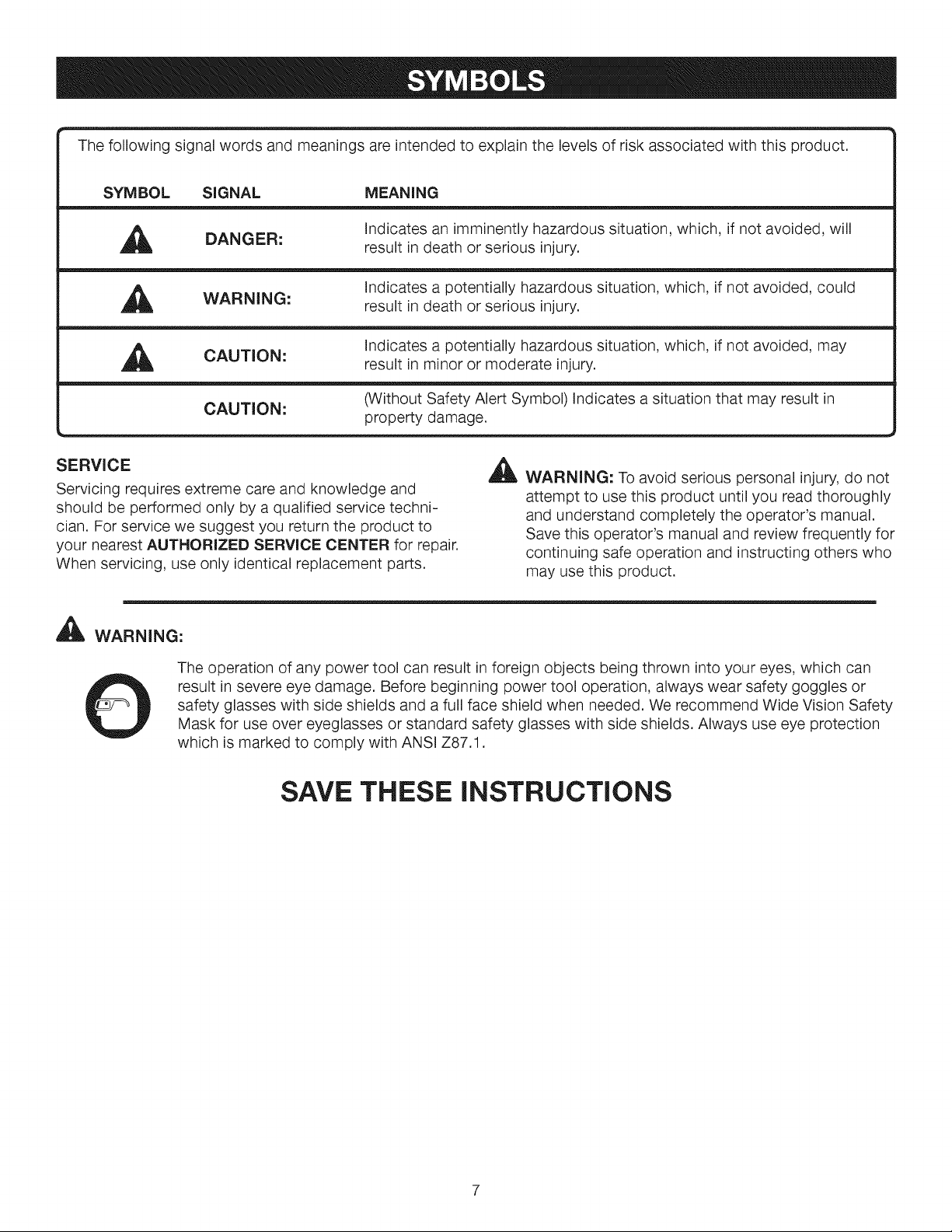
The following signal words and meanings are intended to explain the levels of risk associated with this product.
SYMBOL SIGNAL MEANING
DANGER:
WARNING:
CAUTION:
CAUTION: (Without Safety Alert Symbol) Indicates a situation that may result in
SERVICE
Servicing requires extreme care and knowledge and
should be performed only by a qualified service techni-
cian. For service we suggest you return the product to
your nearest AUTHORIZED SERVICE CENTER for repair.
When servicing, use only identical replacement parts.
,_', WARNING:
The operation of any power tool can result in foreign objects being thrown into your eyes, which can
result in severe eye damage. Before beginning power tool operation, always wear safety goggles or
safety glasses with side shields and a full face shield when needed. We recommend Wide Vision Safety
Mask for use over eyeglasses or standard safety glasses with side shields. Always use eye protection
which is marked to comply with ANSI Z87.1.
Indicates an imminently hazardous situation, which, if not avoided, will
result in death or serious injury.
Indicates a potentially hazardous situation, which, if not avoided, could
result in death or serious injury.
Indicates a potentially hazardous situation, which, if not avoided, may
result in minor or moderate injury.
property damage.
_ WARNING: To avoid serious personal injury, do not
attempt to use this product until you read thoroughly
and understand completely the operator's manual.
Save this operator's manual and review frequently for
continuing safe operation and instructing others who
may use this product.
SAVE THESE INSTRUCTIONS
EXTENSION CORDS
Use only 3-wire extension cords that have 3-prong ground-
ing plugs and 3-pole receptacles that accept the tool's plug.
When using a power tool at a considerable distance from
the power source, use an extension cord heavy enough
to carry the current that the tool will draw. An undersized
extension cord will cause a drop in line voltage, resulting in
a loss of power and causing the motor to overheat. Use the
chart provided below to determine the minimum wire size
required in an extension cord. Only round jacketed cords
listed by Underwriter's Laboratories (UL) should be used.
**Ampere rating (on tool data plate)
0-2.0 2.1-3.4 3.5-5.0 5.1-7.0 7.1-12.0 12.1-16.0
Cord Length Wire Size (A.W.G.)
25' 16 16 16 16 14 14
50' 16 16 16 14 14 12
100' 16 16 14 12 10 --
**Used on 12gauge - 20 amp drcuit.
NOTE: AWG = American Wire Gauge
When working with the tool outdoors, use an extension
cord that is designed for outside use. This is indicated by
the letters "W-A" or "W" on the cord's jacket.
Before using an extension cord, inspect it for loose or
exposed wires and cut or worn insulation.
_IL WARNING: Keep the extension cord clear of the
working area. Position the cord so that it will not get
caught on lumber, tools or other obstructions while
you are working with a power tool. Failure to do so
can result in serious personal injury.
A
WARNING: Check extension cords before each use.
If damaged replace immediately. Never use tool with
a damaged cord since touching the damaged area
could cause electrical shock resulting in serious injury.
A
WARNING: The saw's motor cord must only be
plugged into the receptacle provided on the saw which
is controlled by the saw's master switch. Never plug
the motor cord directly into an extension cord as this
will stop the saw's motor from turning OFF.
ELECTRICAL CONNECTION
This tool is powered by a precision built electric motor.
It should be connected to a power supply that is 120
volts, 60 Hz, AC only (normal household current). Do
not operate this tool on direct current (DC). A substantial
voltage drop will cause a loss of power and the motor will
overheat. If the saw does not operate when plugged into
an outlet, double check the power supply.
SPEED AND WIRING
The no-load speed of this tool is approximately 4,800 rpm.
This speed is not constant and decreases under a load or
with lower voltage. For voltage, the wiring in a shop is as
important as the motor's horsepower rating. A line intend-
ed only for lights cannot properly carry a power tool motor.
Wire that is heavy enough for a short distance will be too
light for a greater distance. A line that can support one
power tool may not be able to support two or three tools.
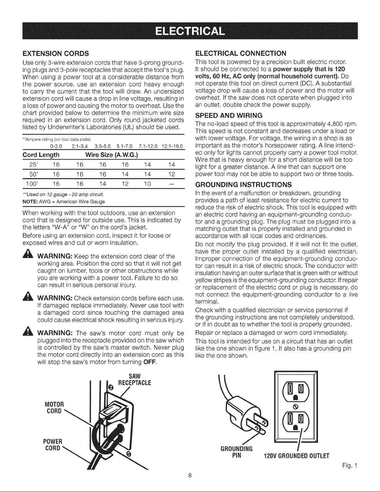
GROUNDING INSTRUCTIONS
Inthe event of a malfunction or breakdown, grounding
provides a path of least resistance for electric current to
reduce the risk of electric shock. This tool is equipped with
an electric cord having an equipment-grounding conduc-
tor and a grounding plug. The plug must be plugged into a
matching outlet that is properly installed and grounded in
accordance with all local codes and ordinances.
Do not modify the plug provided. If it will not fit the outlet,
have the proper outlet installed by a qualified electrician.
Improper connection of the equipment-grounding conduc-
tor can result in a risk of electric shock. The conductor with
insulation having an outer surface that is green with or without
yellow stripes isthe equipment-grounding conductor. If repair
or replacement of the electric cord or plug is necessary, do
not connect the equipment-grounding conductor to a live
terminal.
Check with a qualified electrician or service personnel if
the grounding instructions are not completely understood,
or if in doubt as to whether the tool is properly grounded.
Repair or replace a damaged or worn cord immediately.
This tool is intended for use on a circuit that has an outlet
like the one shown in figure 1. It also has a grounding pin
like the one shown.
MOTOR
CORD
POWER
C0BD
SAW
RECEPTACLE
GROUNDING
PiN 120VGROUNDED OUTLET
Fig. 1

Anti-KickbackPawls (flooring, radial arm, and table
saws)
A device which, when properly installed and maintained,
is designed to stop the workpiece from being kicked back
toward the front of the saw during a ripping operation.
Arbor
The shaft on which a blade or cutting tool is mounted.
Bevel Cut
A cutting operation made with the blade at any angle
other than 90° to the table surface.
Compound Cut
A cross cut made with both a miter and a bevel angle.
Cross Cut
A cutting or shaping operation made across the grain or
the width of the workpiece.
Cutterhead (planers and jointer planers)
A rotating cutterhead with adjustable blades or knives.
The blades or knives remove material from the workpiece.
Dado Cut
A non-through cut which produces a square-sided notch
or trough in the workpiece (requires a special blade).
Featherboard
A device used to help control the workpiece by holding it
securely against the table or fence during any ripping
operation.
FPM or SPM
Feet per minute (or strokes per minute), used in reference
to blade movement.
Freehand
Performing a cut without the workpiece being guided by a
fence, miter gauge, or other aids.
Gum
A sticky, sap-based residue from wood products.
Heel
Alignment of the blade to the fence.
Kerr
The material removed by the blade in a through cut or the
slot produced by the blade in a non-through or partial cut.
Kickback
A hazard that can occur when the blade binds or stalls,
throwing the workpiece back toward operator.
Miter Cut
A cutting operation made with the workpiece at any angle
to the blade other than 90 °.
Non-Through Cuts
Any cutting operation where the blade does not extend
completely through the thickness of the workpiece.
Pilot Hole (drill presses)
A small hole drilled in a workpiece that serves as a guide
for drilling large holes accurately.
Push Blocks (flooring and table saws)
Device used to hold the workpiece during cutting opera-
tions. This aid helps keep the operator's hands well away
from the blade.
Push Blocks 0ointer planers)
Device used to feed the workpiece over the jointer planer
cutterhead during any operation. This aid helps keep the
operator's hands well away from the cutterhead.
Push Sticks (flooring and table saws)
Device used to push the workpiece during cutting opera-
tions. A push stick should be used for narrow ripping
operations. The aid helps keep the operator's hands well
away from the blade.
Resaw
A cutting operation to reduce the thickness of the
workpiece to make thinner pieces.
Resin
A sticky, sap-based substance that has hardened.
Revolutions Per Minute (RPM)
The number of turns completed by a spinning object in
one minute.
Ripping or Rip Cut
A cutting operation along the length of the workpiece.
Riving Knife/Spreader/Splitter (flooring and table
saws)
A metal piece, slightly thinner than the blade, which helps
keep the kerf open and also helps to prevent kickback.
Saw Blade Path
The area over, under, behind, or in front of the blade. As
it applies to the workpiece, that area which will be or has
been cut by the blade.
Set
The distance that the tip of the saw blade tooth is bent (or
set) outward from the face of the blade.
Snipe (planers)
Depression made at either end of a workpiece by cutter
blades when the workpiece is not properly supported.
Through Sawing
Any cutting operation where the blade extends completely
through the thickness of the workpiece.
Throw-Back
The throwing back of a workpiece usually caused by the
workpiece being dropped into the blade or being placed
inadvertently in contact with the blade.
Workpiece or Material
The item on which the operation is being done.
Worktable
Surface where the workpiece rests while performing a
cutting, drilling, planing, or sanding operation.

PRODUCTSPECIFICATIONS
BladeArbor..............................................................5/8in.
BladeDiameter..........................................................10in.
BladeTilt................................................................0°- 45°
Rating...............................................120V,AConly,60Hz
ANTI-KICKBACK
PAWLS
SLIDING
MITER
TABLE
MITERSCALE
RIVING
KNIFE
Input.....................................................................15Amps
NoLoadSpeed....................................4,800r/min.(RPM)
CuttingDepthat0°..............................................3-9/16in.
CuttingDepthat45°..............................................2-1/2in.
GUARD/DUST
COVERWITH
PIVOTASSEMBLY
BLADE
GUARD
ACCESSORY
TABLE
RiP FENCE
ALIGN-A-CUT
INSERT
LOCKING
HANDLE
SCALE
FRONT
BRACE
GAUGE
FRONT
RAiL
STORAGE
BRACKET(S)
BEVEL
SCALE
LEVELING
FOOT
BEVEL
INDICATOR
BEVEL
LOCKING
LEVER
SWITCH
HEiGHT/BEVEL
ADJUSTING
HANDWHEEL
Fig. 2
10
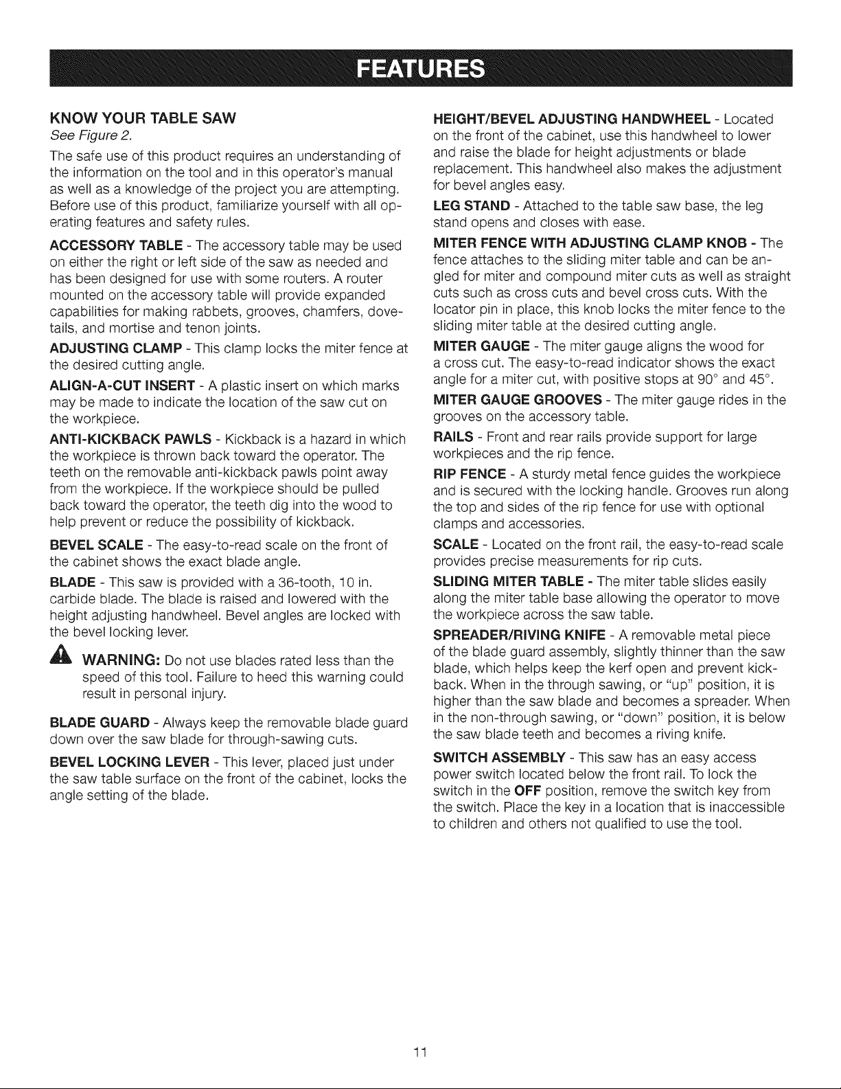
KNOWYOURTABLESAW
See Figure 2.
The safe use of this product requires an understanding of
the information on the tool and in this operator's manual
as well as a knowledge of the project you are attempting.
Before use of this product, familiarize yourself with all op-
erating features and safety rules.
ACCESSORY TABLE - The accessory table may be used
on either the right or left side of the saw as needed and
has been designed for use with some touters. A router
mounted on the accessory table will provide expanded
capabilities for making rabbets, grooves, chamfers, dove-
tails, and mortise and tenon joints.
ADJUSTING CLAMP - This clamp locks the miter fence at
the desired cutting angle.
ALIGN-A-CUT INSERT - A plastic insert on which marks
may be made to indicate the location of the saw cut on
the workpiece.
ANTI-KICKBACK PAWLS - Kickback is a hazard in which
the workpiece is thrown back toward the operator. The
teeth on the removable anti-kickback pawls point away
from the workpiece. If the workpiece should be pulled
back toward the operator, the teeth dig into the wood to
help prevent or reduce the possibility of kickback.
BEVEL SCALE - The easy-to-read scale on the front of
the cabinet shows the exact blade angle.
BLADE - This saw is provided with a 36-tooth, 10 in.
carbide blade. The blade is raised and lowered with the
height adjusting handwheel. Bevel angles are locked with
the bevel locking lever.
WARNING-" Do not use blades rated less than the
speed of this tool. Failure to heed this warning could
result in personal injury.
BLADE GUARD - Always keep the removable blade guard
down over the saw blade for through-sawing cuts.
BEVEL LOCKING LEVER - This lever, placed just under
the saw table surface on the front of the cabinet, locks the
angle setting of the blade.
HEIGHT/BEVEL ADJUSTING HANDWHEEL- Located
on the front of the cabinet, use this handwheel to lower
and raise the blade for height adjustments or blade
replacement. This handwheel also makes the adjustment
for bevel angles easy.
LEG STAND - Attached to the table saw base, the leg
stand opens and closes with ease.
MITER FENCE WITH ADJUSTING CLAMP KNOB - The
fence attaches to the sliding miter table and can be an-
gled for miter and compound miter cuts as well as straight
cuts such as cross cuts and bevel cross cuts. With the
Iocator pin in place, this knob locks the miter fence to the
sliding miter table at the desired cutting angle.
MITER GAUGE - The miter gauge aligns the wood for
a cross cut. The easy-to-read indicator shows the exact
angle for a miter cut, with positive stops at 90° and 45°.
MITER GAUGE GROOVES - The miter gauge rides in the
grooves on the accessory table.
RAILS - Front and rear rails provide support for large
workpieces and the rip fence.
RIP FENCE - A sturdy metal fence guides the workpiece
and is secured with the locking handle. Grooves run along
the top and sides of the rip fence for use with optional
clamps and accessories.
SCALE - Located on the front rail, the easy-to-read scale
provides precise measurements for rip cuts.
SLIDING MITER TABLE - The miter table slides easily
along the miter table base allowing the operator to move
the workpiece across the saw table.
SPREADER/RIVING KNIFE - A removable metal piece
of the blade guard assembly, slightly thinner than the saw
blade, which helps keep the kerf open and prevent kick-
back. When in the through sawing, or "up" position, it is
higher than the saw blade and becomes a spreader. When
in the non-through sawing, or "down" position, it is below
the saw blade teeth and becomes a riving knife.
SWITCH ASSEMBLY - This saw has an easy access
power switch located below the front rail. To lock the
switch in the OFF position, remove the switch key from
the switch. Place the key in a location that is inaccessible
to children and others not qualified to use the tool.
11
OPERATINGCOMPONENTS
Theupperportionofthebladeprojectsupthroughthe
tableandissurroundedbyaninsertcalledthethroat
plate.Theheightofthebladeissetwithahandwheelon
thefrontofthecabinet.Toaccommodatewidepanels,
thesawtablehasrailsoneachside.Detailedinstructions
areprovidedintheOperation section of this manual for
the basic cuts: cross cuts, miter cuts, bevel cuts, and
compound cuts.
The sliding miter table assembly is used for cross cutting
operations. The miter fence is easily adjusted to cut wood
at an angle by loosening the adjusting clamp, setting the
fence to the miter scale, and retightening the clamp. The
sliding miter table, which rests on a base mounted on the
rails, can be repositioned along the rails for wide work. It
can be reversed so the projecting base is in the back and
can be moved from the left side to the right side as need-
ed. With the miter fence removed, the miter table offers
additional support for other operations such as ripping.
The rip fence is used to position work for lengthwise cuts.
A scale on the front rail shows the distance between the
rip fence and the blade.
It is very important to use the blade guard assembly for all
through-sawing operations. The blade guard assembly
includes: riving knife/spreader/splitter, anti-kickback
pawls, and plastic blade guard.
The saw features a receptacle on the right side of the
cabinet that permits use of accessories. Use only acces-
sories that are listed for use with this tool. When using a
listed accessory, unplug the saw motor cord and use the
receptacle and the saw's power switch to operate the
accessory.
A
WARNING: Always remove the switch key when
the tool is not in use and keep it in a safe place.
In the event of a power failure, turn the switch off
( O ) and remove the key. This action will prevent the
tool from accidentally starting when power returns.
A
WARNING: ALWAYS make sure your workpiece is
not in contact with the blade before operating the
switch to start the tool. Failure to heed this warning
may cause the workpiece to be kicked back toward
the operator and result in serious personal injury.
A
WARNING: To reduce the risk of accidental start-
ing, Always make sure the switch is in the off ( O )
position before plugging tool into the power source.
SWITCH
ON
SWITCH
OFF
(
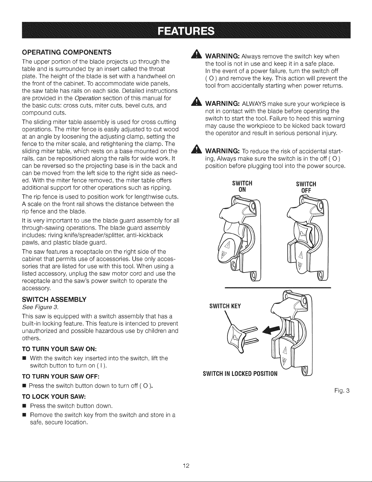
SWITCH ASSEMBLY
See Figure 3,
This saw is equipped with a switch assembly that has a
built-in locking feature. This feature is intended to prevent
unauthorized and possible hazardous use by children and
others.
TO TURN YOUR SAW ON:
[] With the switch key inserted into the switch, lift the
switch button to turn on (I).
TO TURN YOUR SAW OFF:
[] Press the switch button down to turn off ( O ).
TO LOCK YOUR SAW:
[] Press the switch button down.
[] Remove the switch key from the switch and store in a
safe, secure location.
SWITCHKEY
SWITCHIN LOCKEDPOSITION
Fig. 3
12
BLADES ,_
For maximum performance, it is recommended that you
use the 36-tooth, 10 in. carbide-tipped combination blade
provided with your saw. Additional blade styles of the
same high quality are available for specific operations
such as ripping. Your local dealer can provide you with
complete information.
Kerf width must be within the limits stamped on the
spreader/riving knife.
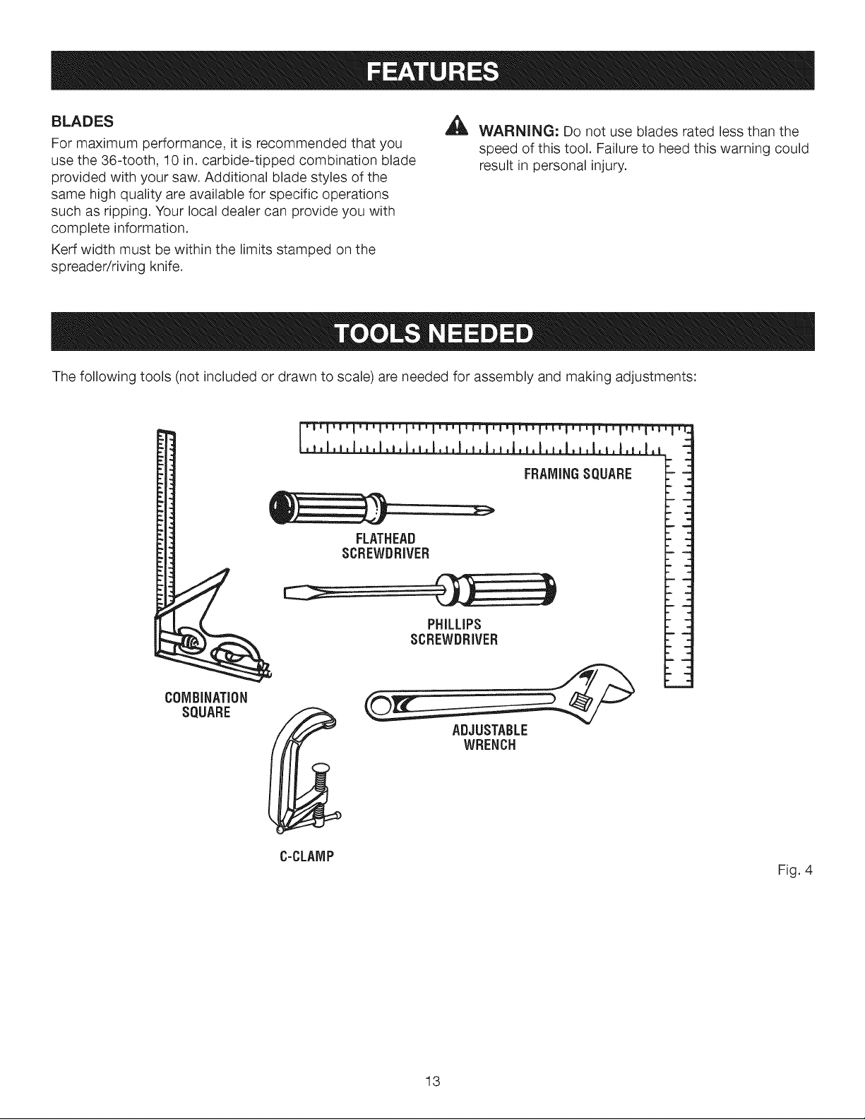
The following tools (not included or drawn to scale) are needed for assembly and making adjustments:
_l,l,l,l,i,l,l,l,l,l,l,l,I, i,I,i,I,o
WARNING: Do not use blades rated less than the
speed of this tool. Failure to heed this warning could
result in personal injury.
FRAMINGSQUARE
COMBiNATiON
SQUARE
FLATHEAD
SCREWDRIVER
PHILLIPS
SCREWDRIVER
ADJUSTABLE
WRENCH
C-CLAMP
Fig. 4
13
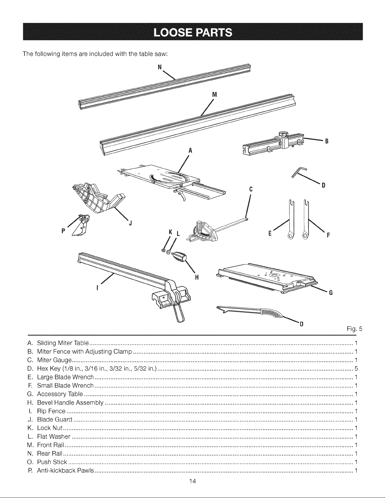
Thefollowingitemsareincludedwiththetablesaw:
Fig.5
A. SlidingMiterTable.......................................................................................................................................................1
B. MiterFencewithAdjustingClamp..............................................................................................................................1
C. MiterGauge.................................................................................................................................................................1
D. HexKey(1/8in.,3/16in.,3/32in.,5/32in.)................................................................................................................5
E. LargeBladeWrench....................................................................................................................................................1
R SmallBladeWrench....................................................................................................................................................1
G.AccessoryTable..........................................................................................................................................................1
H. BevelHandleAssembly..............................................................................................................................................1
I. RipFence....................................................................................................................................................................1
J. BladeGuard................................................................................................................................................................1
K. LockNut......................................................................................................................................................................1
L. FlatWasher.................................................................................................................................................................1
M. FrontRail.....................................................................................................................................................................1
N. RearRail......................................................................................................................................................................1
O. PushStick...................................................................................................................................................................1
R Anti-kickbackPawls....................................................................................................................................................1
14
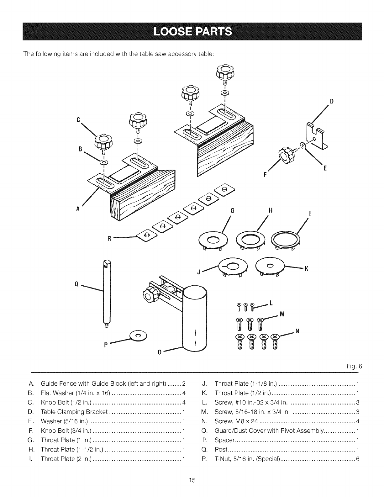
Thefollowingitemsareincludedwiththetablesawaccessorytable:
I
|
i E
F
iVI
A. Guide Fence with Guide Block (left and right) ........ 2
B. Flat Washer (1/4 in. x 16) ........................................ 4
C. Knob Bolt (1/2 in.) ................................................... 4
D. Table Clamping Bracket .......................................... 1
E. Washer (5/16 in.) ..................................................... 1
R Knob Bolt (3/4 in.) ................................................... 1
G. Throat Plate (1 in.) ................................................... 1
H. Throat Plate (1-1/2 in.) ............................................ 1
I. Throat Plate (2 in.) ................................................... 1
Fig. 6
J. Throat Plate (1-1/8 in.) ............................................ 1
K. Throat Plate (1/2 in.)................................................ 1
L. Screw, #10 in.-32 x 3/4 in...................................... 3
M. Screw, 5/16-18 in. x 3/4 in ..................................... 3
N. Screw, M8x24 ....................................................... 4
O. Guard/Dust Cover with Pivot Assembly .................. 1
R Spacer ..................................................................... 1
Q. Post ......................................................................... 1
R. T-Nut, 5/16 in. (Special) ........................................... 6
15
UNPACKING
This product requires assembly.
[] Carefully lift saw from the carton and place it on a level
work surface.
NOTE: This tool is heavy. To avoid back injury, keep
your knees bent and lift with your legs, not your back,
and get help when needed.
A
WARNING: Do not use this product if any parts on
the Loose Parts List are already assembled to your
product when you unpack it. Parts on this list are not
assembled to the product by the manufacturer and
require customer installation. Use of a product that
may have been improperly assembled could result in
serious personal injury.
[] Inspect the tool carefully to make sure no breakage or
damage occurred during shipping.
[] Do not discard the packing material until you have
carefully inspected the tool, identified all loose parts,
and satisfactorily operated the tool.
[] The saw is factory set for accurate cutting. After
assembling it, check for accuracy. If shipping has
influenced the settings, refer to specific procedures
explained in this manual.
[] If any parts are damaged or missing, please call
1-800-932-3188 for assistance.
WARNING: Never stand directly in line with the
blade or allow hands to come closer than 3 in. to the
blade. Do not reach over or across the blade. Failure
to heed this warning can result in serious _ersonal
injury.
A
WARNING: To avoid serious personal injury,
always make sure the table saw is securely mounted
to a workbench or an approved leg stand. NEVER
operate the saw on the floor.
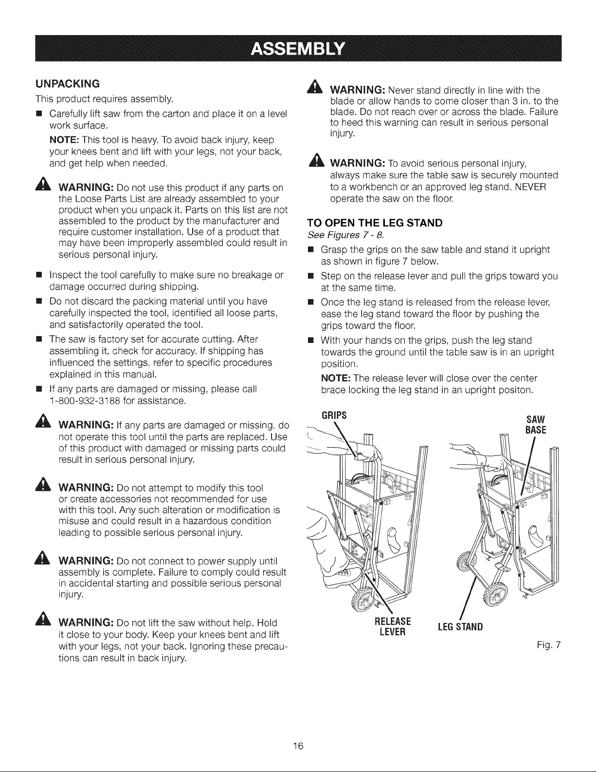
TO OPEN THE LEG STAND
See Figures 7- 8.
[] Grasp the grips on the saw table and stand it upright
as shown in figure 7 below.
[] Step on the release lever and pull the grips toward you
at the same time.
[] Once the leg stand is released from the release lever,
ease the leg stand toward the floor by pushing the
grips toward the floor.
[] With your hands on the grips, push the leg stand
towards the ground until the table saw is in an upright
position.
NOTE: The release lever will close over the center
brace locking the leg stand in an upright positon.
,&
WARNING: If any parts are damaged or missing, do
not operate this tool until the parts are replaced. Use
of this product with damaged or missing parts could
result in serious personal injury.
A
WARNING: Do not attempt to modify this tool
or create accessories not recommended for use
with this tool. Any such alteration or modification is
misuse and could result in a hazardous condition
leading to possible serious personal injury.
A
WARNING: Do not connect to power supply until
assembly is complete. Failure to comply could result
in accidental starting and possible serious personal
injury.
A
WARNING: Do not lift the saw without help. Hold
it close to your body. Keep your knees bent and lift
with your legs, not your back. Ignoring these precau-
tions can result in back injury.
GRIPS SAW
\ BASE
RELEASE
LEVER LEGSTAND
Fig. 7
16
WING NUT
RELEASE
LEVER
BRACE
Fig. 8
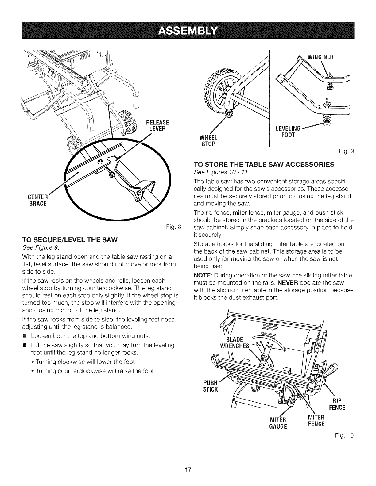
TO SECURE/LEVEL THE SAW
See Figure 9.
With the leg stand open and the table saw resting on a
flat, level surface, the saw should not move or rock from
side to side.
If the saw rests on the wheels and rolls, loosen each
wheel stop by turning counterclockwise. The leg stand
should rest on each stop only slightly. If the wheel stop is
turned too much, the stop will interfere with the opening
and closing motion of the leg stand.
If the saw rocks from side to side, the leveling feet need
adjusting until the leg stand is balanced.
[] Loosen both the top and bottom wing nuts.
[] Lift the saw slightly so that you may turn the leveling
foot until the leg stand no longer rocks.
• Turning clockwise will lower the foot
Turning counterclockwise will raise the foot
LEVELING
WHEEL
STOP
TO STORE THE TABLE SAW ACCESSORIES
See Figures 10- 11.
The table saw has two convenient storage areas specifi-
cally designed for the saw's accessories. These accesso-
ries must be securely stored prior to closing the leg stand
and moving the saw.
The rip fence, miter fence, miter gauge, and push stick
should be stored in the brackets located on the side of the
saw cabinet. Simply snap each accessory in place to hold
it securely.
Storage hooks for the sliding miter table are located on
the back of the saw cabinet. This storage area is to be
used only for moving the saw or when the saw is not
being used.
NOTE: During operation of the saw, the sliding miter table
must be mounted on the rails. NEVER operate the saw
with the sliding miter table in the storage position because
it blocks the dust exhaust port.
FOOT
Fig. 9
17
PUSHt _::__.__ _/_/_
MITER MITER
GAUGE FENCE
Fig. 10
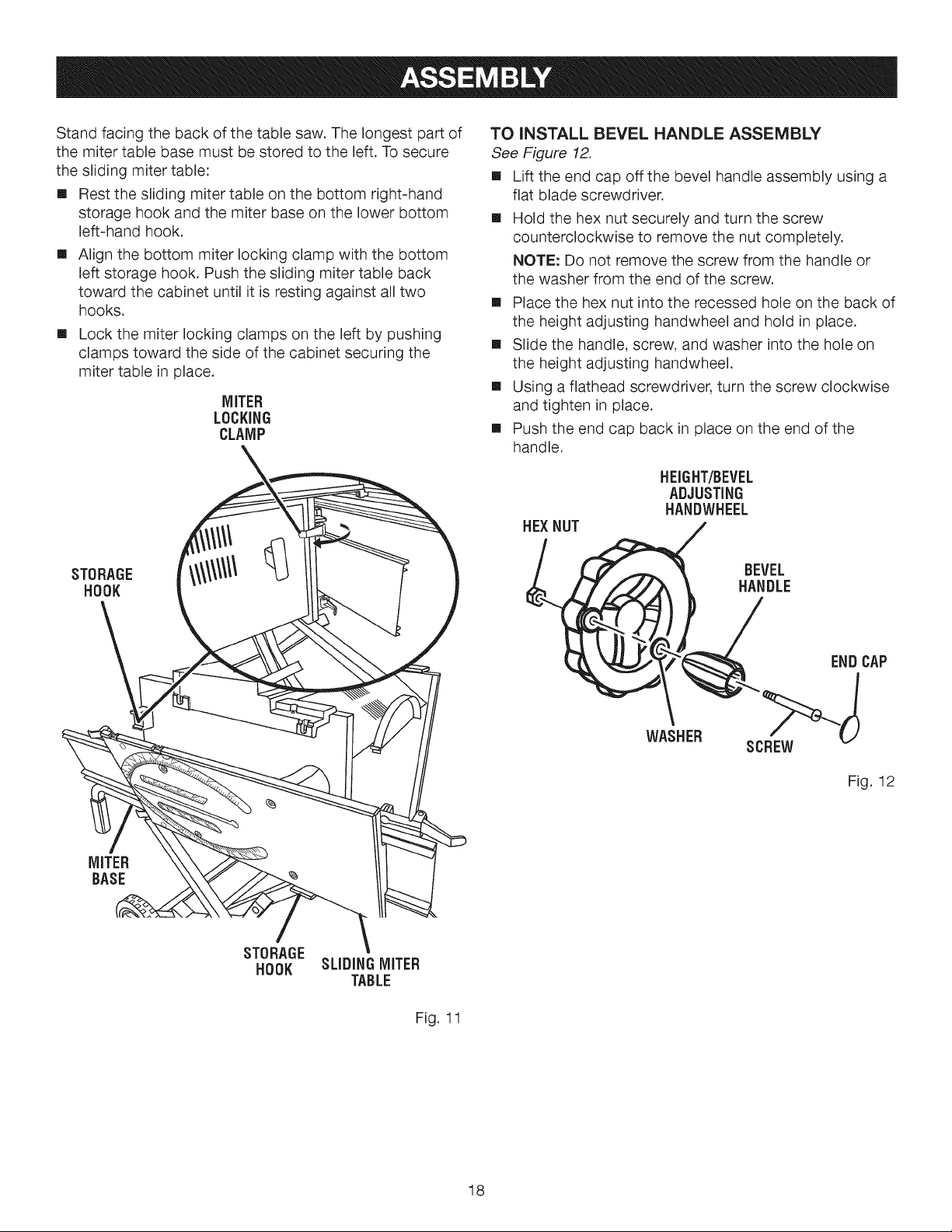
Standfacingthebackofthetablesaw.Thelongestpartof
themitertablebasemustbestoredtotheleft.Tosecure
theslidingmitertable:
[] Resttheslidingmitertableonthebottomright-hand
storagehookandthemiterbaseonthelowerbottom
left-handhook.
[]
Align the bottom miter locking clamp with the bottom
left storage hook. Push the sliding miter table back
toward the cabinet until it is resting against all two
hooks.
[]
Lock the miter locking clamps on the left by pushing
clamps toward the side of the cabinet securing the
miter table in place.
MITER
LOCKING
CLAMP
TO iNSTALL BEVEL HANDLE ASSEMBLY
See Figure 12.
[] Lift the end cap off the bevel handle assembly using a
flat blade screwdriver.
[] Hold the hex nut securely and turn the screw
counterclockwise to remove the nut completely.
NOTE: Do not remove the screw from the handle or
the washer from the end of the screw.
[] Place the hex nut into the recessed hole on the back of
the height adjusting handwheel and hold in place.
[] Slide the handle, screw, and washer into the hole on
the height adjusting handwheel.
[] Using a flathead screwdriver, turn the screw clockwise
and tighten in place.
[] Push the end cap back in place on the end of the
handle.
HEIGHT/BEVEL
ADJUSTING
HANDWHEEL
HEX NUT
STORAGE
HOOK
MITER
BASE
%
STORAGE
HOOK
SLiDiNG MITER
TABLE
Fig. 11
WASHER
BEVEL
HANDLE
END CAP
>-J
SCREW
Fig. 12
18
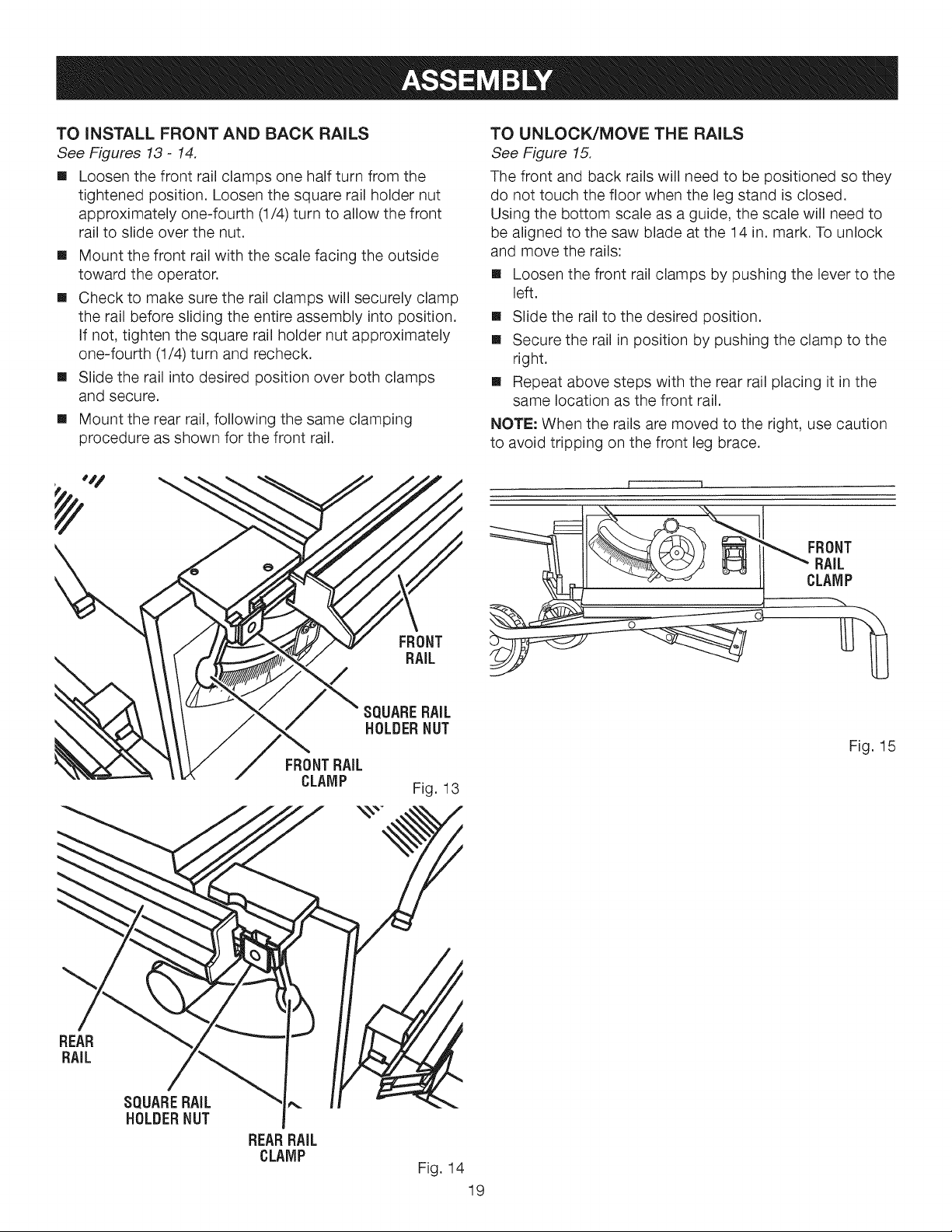
TO (NSTALL FRONT AND BACK RA(LS
See Figures 13- 14.
[] Loosen the front rail clamps one half turn from the
tightened position. Loosen the square rail holder nut
approximately one-fourth (1/4) turn to allow the front
rail to slide over the nut.
[] Mount the front rail with the scale facing the outside
toward the operator.
[] Check to make sure the rail clamps will securely clamp
the rail before sliding the entire assembly into position.
If not, tighten the square rail holder nut approximately
one-fourth (1/4) turn and recheck.
[] Slide the rail into desired position over both clamps
and secure.
[] Mount the rear rail, following the same clamping
procedure as shown for the front rail.
TO UNLOCK/MOVE THE RAILS
See Figure 15.
The front and back rails will need to be positioned so they
do not touch the floor when the leg stand is closed.
Using the bottom scale as a guide, the scale will need to
be aligned to the saw blade at the 14 in. mark. To unlock
and move the rails:
[] Loosen the front rail clamps by pushing the lever to the
left.
[] Slide the rail to the desired position.
[] Secure the rail in position by pushing the clamp to the
right.
[] Repeat above steps with the rear rail placing it in the
same location as the front rail.
NOTE: When the rails are moved to the right, use caution
to avoid tripping on the front leg brace.
i i
REAR
RAIL
FRONTBAIL
CLAMP
FRONT
RAIL
SQUARE BAiL
HOLDER NUT
Fig. 15
Fig. 13
SQUARE BAiL
HOLDER NUT
BEAR BAIL
CLAMP
Fig. 14
19
TO CLOSE THE LEG STAND AND MOVE THE
SAW
See Figure 16.
Store the sliding miter table on the back of the saw
cabinet. See To Store the Table Saw Accessories on the
previous page. Next, set the front and back rails to 14 in.
as previously described.
NOTE: Never close the leg stand or attempt to move the
table saw until both the above steps are completed.
To close the leg stand:
[] At the same time, step on the release lever, grasp the
grips, and lift the handles up and away from the body.
[] Push the table saw until the release lever clicks and
locks into place.
To move the leg stand:
[] Holding the grips firmly, pull the handles toward
you until the leg stand and saw are balanced on the
wheels.
[] Push the saw to the desired location then either open
the leg stand for immediate saw operation or store the
saw in a dry environment.
NOTE: Never move the table saw unless the sliding miter
table is securely stored.
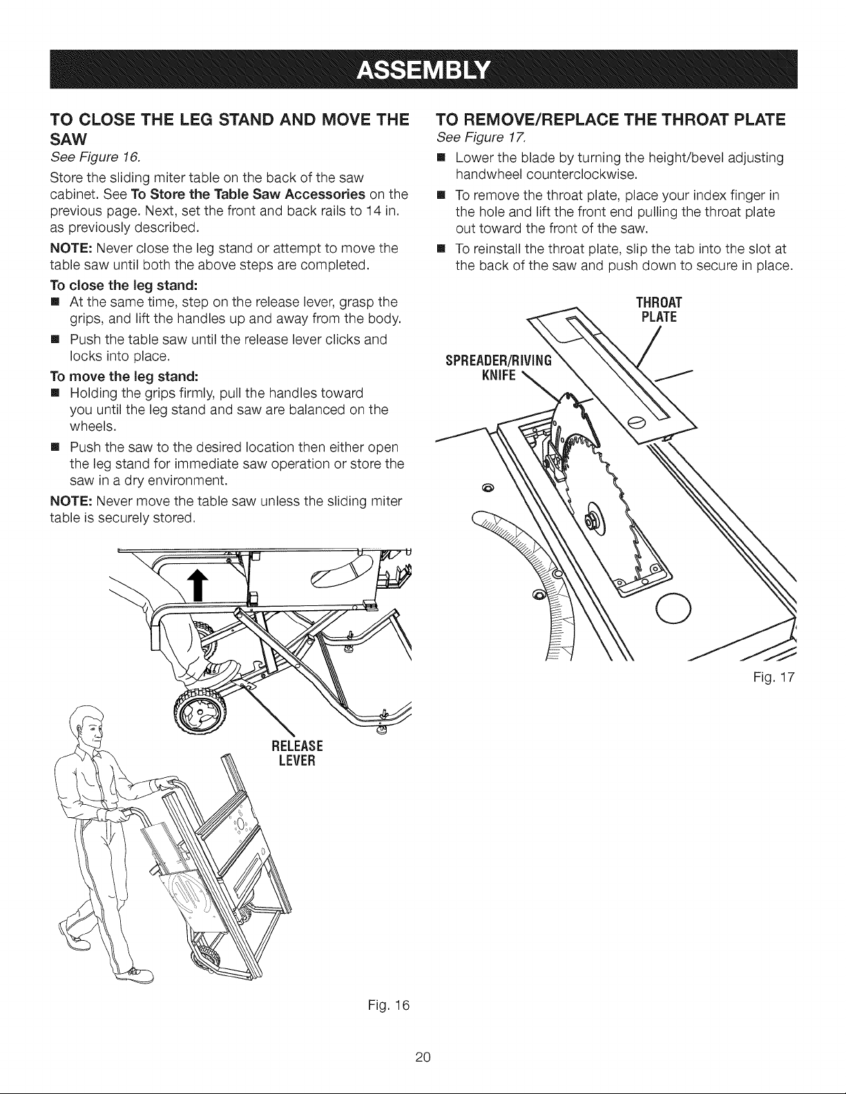
TO REMOVE/REPLACE THE THROAT PLATE
See Figure 17.
[] Lower the blade by turning the height/bevel adjusting
handwheel counterclockwise.
[] To remove the throat plate, place your index finger in
the hole and lift the front end pulling the throat plate
out toward the front of the saw.
[] To reinstall the throat plate, slip the tab into the slot at
the back of the saw and push down to secure in place.
THROAT
PLATE
SPREADER/RIVING
KNIFE
'\
Fig. 17
RELEASE
LEVER
Fig. 16
20
 Loading...