

Craftsman 315218060 Owner’s Manual

_ WARNING: To reduce the risk of injury, the
user must read and 'Jnderstand the operator's
manual before using this product.
Customer Help Line: 1-800-932-3188
Sears, Roebuck and Co., 3333 Beverly Rd., Hoffman Estates, IL 60179 USA
Visit the Craftsman web page: w_,.sears.com/craftsman
983000-696
6-30-05
Save this manual for future reference

[] Waoanty ........................................................................................................................................................................ 2
Introduchon ..................................................................................................................................................................... 2
I_ General Sa(ety Rules ...............................................................................................................................................
Specific Safety Rules ................................................................................................................................................... 4-5
Symbols ....................................................................................................................................................................... 6-7
D _lectrical .............
u Glossar_ of Terr_s .......................................................................................................................................................... 9
E] Features ........................................................................................................................................................... 10-13
[] Tools Needed ................................................................................................................................................................. 13
"_ LOOSe Pads ................
........................................................................................................................................... 14
a Assembl_. ..................................................................................................................................................... t5-19
_3 Operation ................................................................................................................................................................. 19-34
a Adjustments .......................................................................................................................................................... 35-37
[3 Maintenance ............................................................................................................................................................ 38
Troublesheot..ng ....................................................................................................................................................... 39-40
Fx ploded View ...................................................................................................................................................... 43-50
_a Parts Ordedncj/Service .................................................................................................................................... Back Page
ONE YEAR FULL WARRANTY ON CRAFTSMAN TOOL
If this Craftsman tool fails due _o a detect in material or workmanship within one year from the dale of purchase. Call
1-800-4-MY-HOME ® to arrange for free repai_ If this tool is used for commercial or rental purposes, this warranty will
apply for only ninety days from the date of purchase This warranty applies onty while t_qis product is in the United States.
This warranty gives you spec tic lega r ghts, and you may also have other rights which vary t_om state to stale.
Sears, Roebuck and Ce., Dept. 817WA, Hoffman Estates, IL 60179
This loci has many features for making its use more pleasant and enjoyable. Safety, performance, and dependability
l_ave been given top priority in the design of this product makiFg it easy to maintain and operate.
A WARNING:Read and understand all ]nstruc-
gone. Failure to follow all instructions listed below,
may result in electric shock, fire and/or serious
persona_ injury.
READ ALL INSTRUCTIONS
13 KNOW YOUR POWER TOOL. Read the operator's
manuc_l c_llefu[iy. Lealn the saw's applications and
limitations as well as the specific potential hazards
related to this tool.
[_ GUARD AGAINST ELECTRICAL SI-IOCK BY PRE-
VENTING BODY CONTACT WITH GROUNDED
SURFACES. For exampte, pipes, radiators, ranges,
refrigerator enclosures.
g KEEP GUARDS IN PLACE and in good working order:
_] REMOVE ADJUSTING KEYS AND WRENCHES,
Form habit of checking to see thai k.eys and adjusting
wrenches are removed from tool before turning it on.
B KEEP WORK AREA CLEAN. Cluttered areas and
benches invge accidents. DO NOT leave tools or
pieces of wood on the saw while it is in operation,
[1 DO NOT USE IN DANGEROUS ENVIRONMENTS.
Do not use power tools in damp or we{ locations or
expose to rain. Keep the work area well lit.
B KEEP CHILDREN AND VISITORS AWAY. All visitors
should wear safety glasses end be kept a safe
distance from work area, Do not let visitors contact
tool or extension cord while operating.
a MAKE WORKSHOP ONILDPROOF with padlocks and
master switches, or by removing starter keys.
B DON'T FORCE TOOL. It will do the job better and
safer at the feed rate for which it was designed.
8 USE RIGHT TOOL. Don't force the tool or attachment
to do a iob il was not designed for. Don't use it for a
purpose not intended.
8 USE THE PROPER EXTENSION CORD. Make sure
your extension cord Js in good condition. Use only a
cord heavy enough to carry the current your product
wilt draw. An undersized cord will cause a diop ir_ line
voltage resulting in loss of power and overheating. A
wire gauge size (A.W.G) of at least 14 is recommended
for an extension cord 25 feet or less in length, If in
doubt, use the r_ext heavier gauge The smaller the
gauge number, the heavier the oord.
pa DRESS PROPERLY. Do act wear IoosecIothing,
gloves, neckties, or jewelry. They can _et caughl
and draw you into moving parLs Rubber gloves and
nonskid footwear are recommended when working
outdoors. Aieo wear protective hair covering to contain
}cog hair.
B ALWAYS WEAR SAFETY GLASSES WITH SIDE
SHIELDS, Everyday eyeglasses have only impact-
resistant lenses, they are NOT safety glasses,
i_ SECURE WORK. Use clamps or a visa to hold wed{
when practical. It's safer than using your hand and
frees both hands to operate tool
a DON_T OVERREACH. Keep proper fooling and
balance at all times.
8 MAINTAIN TOOLSWITH CARE. Keep tools sharp
and clean for better and safer performance. Follow
instructions fo_ lubFicating and changing accessories
_] DISCONNECT TOOLS. When not in use, before
servicing, or when changing attachments, blades, bits.
cutters, etc., all toots should be disconnected.
F3 AVOID ACCIDENTAL STARTING. Be sure switch is off
when plugging in any tool.
g USE RECOMMENDED ACCESSORIES. Consult the
operators manual Ior recommended accessories. The
use of improper accessories may risk iniury.
D NEVER STAND ON TOOL. Serious injury could occur
it the tool is tipped or if the cutting tool is uninlention-
ally contacted•
13 CHECK DAMAGED PARTS. Before further use of
the tool, a guard or other pad that is damaged should
be carefulry checked to determ, ine that it will operate
properly and penlorm its intended function. Check for
alignment of moving paris, binding of moving parts,
breakage of pans, n7ounting and any other conditions
thai may affect its operation. A guard or other part thai
is damaged must be properly repaired or replaced by
an authorized set&,ice center to avoid risk of personal
injury.
B USE THE RIGHT DIRECTION OF FEED, Feed work
into a blade or cutter against the direction of rotation of
blade or cutter only,
B NEVER LEAVE TOOL RUNNING UNATTENDED.
TURN THE POWER OFF. Don't leave tool until it
comes to a complele slop.
PROTECT YOUR LUNGS. Wear a face or dust mask if
the cutting operation is dusty.
u PROTECT YOUR HEARING. Wear hearing protection
ddring extended periods of operation.
B DO NOT ABUSE CORD. Never yank cord to discon-
nect from receptacle. Keep cord from heat, oil. and
sharp edges,
[] USEOUTDOOR EXTENSION CORDS. When tool
is used outdoors, use only extension cords wilh
approved ground cormection that a_e intended for use
outdoors and so marked.
ALWAYS KEEP THE BLADE GUARD AND RIVING
KNIFE/SPREADER/SPLITTER IN PLACE and in
working order,
B KEEP BLADES CLEAN, SHARP, AND WITH
SUFFICIENT SET. Sharp btades minimize stalting
and kickback.
[_ KEEP HANDS AWAY FROM CUTTING AREA. Keep
hands away from blades Do not reach underpeath
3
- ..; . . . " . . . ..
• • :- • " • • . ; "i .
work or around or over the blade while blade is
rotating. Do not attempt to remove cut material when
blade is moving,
[] BLADE COASTS AFTER BEING TURNED OFF.
e NEVER USE IN AN EXPLOSIVE ATMOSPHERE•
Normal sparking of the motor could ignite fumes.
B INSPECT TOOL CORDS PERIODICALLY• If damaged,
have repaired by a qualified service lechnician at
an authorized service (acillty. The conductor with
insulation having an outer surface that is green w_th
or without yellow stripes is the equbrnent-ground-
ing conductor. If repair or replacement of the electric
cord or plug is necessa!% do not connect the equip-
ment-grounding conductor to a live terminal Repair
er replace a damaged or worn cord immediately. Stay
constanUyawareofcordlocationend keep itweiraway
fromtherotatingblade.
INSPECT EXTENSION CORPS PERIODICALLY and
replaceifdamaged,
E]GROUND ALL TOOLS. Iftoolisequipped withthree-
prongplug,itshouldbe pluggedintoa three-hob
e}ectrlcalreceptacle.
B CHECK WITH A QUALIFIED ELECTRtCIAN or service
personnel if the grounding instructions are not com-
pletely understood or if in doubt as to whether the toe]
is properly grounded.
[] USE ONLY CORRECT ELECTRICAL DEVICES: 3-wire
extension cords that have 3-proeg grounding plugs and
3-pole receptacles that accept the tool's plug.
a DO NOT MODIFY the plug provided. II itwiU not tit the
outlet, have the proper outlet installed by a qualified
electrician•
_1 KEEP TOOL DRY, CLEAN, AND FREE FROM OIL
AND GREASE. Always use a clean cloth when clean-
ing. Never use brake fluids, gasoline, petroleum-based
products, or any solvents to clean tool,
STAY ALERT AND EXERCISE CONTROL, Watch
what you are doing and use common sense. Do not
operate tool when you are tired. Do not rush.
DO NOT USE TOOL IF SWITCH DOES NOT TURN IT
ON AND OFF. Have defeegve switches replaced by an
authorized service center.
la USE ONLY CORRECT BLADES. Do not use blades
with incorrect size holes. Never use blade washers or
blade bolts that are defective or incorrect. The maxi-
mum blade capacity of your saw is 10 in. (254 ram).
_9 BEFORE MAKING A CUT, BE SURE ALL ADJUST-
MENTS ARE SECURE.
Z] BE SURE BLADE PATH ISFREE OF NAILS. Inspect
[or and remove all nails from turnber before cutting.
B NEVER TOUCH BLADE or other moving parts during
use,
t_ NEVER START ATOOL WHEN ANY ROTATING COM-
PONENT IS IN CONTACT WITH THE WORKPIECE.
_' DO NOT OPERATE A TOOL WHILE UNDER THE
INFLUENCE OF DRUGS, ALCOHOL, OR ANY
MEDICATION.
I_1WHEN SERVICING use only identical replacement
parts. Use of any other pads may create a hazard or
cause product damage.
li_ USE ONLY RECOMMENDED ACCESSORIES listed
in this manual or addendums. Use of accessories
that are net listed may cause the risk of personal
injury, instructions for safe use of accessories are
included with the accessory.
B DOUBLE CHECK ALL SETUPS, Make sure blade is
tight and not making contact with saw or workpiece
before connecting to power supply•
• :-. •.
GUARD AGAtNST KICNBACK. Kickback occurs
when the blade stalls rapidly and workplace is driven
back towards the operator• It can pull your hand into
the blade resulting in echoes personal injury. Stay out
of blade path and turn switch off immediately if blade
binds or stalls.
a USE RIP FENCE. Always use a fence or straight edge
guide when rippir, g,
SUPPORT LARGE PANELS. To minimize risk of blade
pinching and Idckbaek, atways support large panels.
el REMOVE ALL FENCES AND AUXILIARY TABLES
belore trenspaJting saw. Failure to do so can "esult in
an accident causing possibie serious personal injun/.
ra ALWAYS USE BLADE GUARD, RIVING KNIFE/
SPREADER/SPLITTER, AND ANTI-KICKBACK
PAWLS on all "through-sawing' operations. Through-
sawing operations are those inwhich the blade cuts
completely Ihrough the workpiece as in ripping or
cross cutting. Keep lhe blade guard down, the anti-
kickbaak pawls down, and the riving knifeispreeded
splitter properly aligned to the saw blade.
ALWAYS SECURE WORK firmly against rip fence,
miter fence, or miter gauge.
ALWAYS USE A PUSH STICK FOR RIPPING NAR-
ROW STOCK. A push stick is a dev=ce used to push
a werkpiece through the blade instead of using your
hands Size and shape can vary but the push stick must
always De narrower than tbe wofi_piece to prevent the
push stick from contacting the saw blade. When ripping
narrew stock, always use a push stick, so your hand does
not come close to the saw blade. Use a featherbeard and
push blocks for oemthrough cuts
f_ NEVER perform any operation "|reehand" which
means using only your hands to support or guide the
workpiece, Always use either the rip tence or miler
fence to posRion and guide the work.
m NEVER ste,_d or t'_ve any part of your body in line
with the path of fhe saw blade.
NEVER reach behind, over, or within three inches of
the brads or cutter with either hand for any reason,
_, MOVE THE RIP FENCE out of the way when cross
cutting•
B NEVER use tip fence as cutoff gauge when c_'oss
cutting.
13 NEVER attempt to free a statted saw blade without
first turning the saw OFF and disconnecting the saw
from tr_e power source.
8 PROVIDE ADEQUATE SUPPORT to the rear and
sides of the saw table for wide or long work pieces•
Use a sturdy "oufriggar" suppoll it a table extension
more than 24 inches long is attached to the saw.
AVOID K_OKBACKS (work throwr_ back toward 'you}
by:
a_ Keeping b_ade sharp.
b) Keeping rip fence parallel to the saw blade•
c} Keeping dvir',9 _,£itelspreader/splittar, anti-kickback
pawls, and blade guard in place and operating•
d) Not r=Jeasi_g the work before it (s pushed all the
way past the saw blade using a push stick•
e) Not ripping work. that is b.eisted or warped or does
not have a straight edge to guide along the fence.
AVOID AWl{WARD OF'ERATIONS AND HAND
POSITIONS where a sudder_ slip could cause your
hand to m,_ve into the cutting tool
USE ONLY RECOMMENDED ACCESSORIES [isled in
this marius[ or adder_dums. Use of accessories that are
not listed may cause Ihe risk of personal injury. Instruc-
tions for safe use of accessories are included with the
accessory.
c_ I'.",AKESURE THE WORN AREA HAS AMPLE LIGHT-
ING to see the work and that no obstructions will inter-
fore with safe operation BEFORE performing any work
usingthe table saw.
n ALWAYS TURN OFF SAW before disconnecting it, to
a'Joid accidental staffing when reconnecting to power
supply•
THIS TOOL should have the following markings:
a) Wear eye protection.
b) Useeawbladeguardandrivingl_nffe/spreaded
splitter for every operation for whicll it can be
used, including all through sawing.
c] Keep hands out of the line of saw blade.
d) Use a push stick when required.
e) Pay particular altention to instructions on reducing
risk of kickbacK.
0 DOnot perform any operation freehand.
g) Nevei" leach around or over the saw blade.
e SAVETRESE INSTRUCTIONS, Refer to them
frequently and use toinstruct other users. Ifyou loan
someone this tool, loan them these instructions also.
_ WARNIN6: Some dust created by power sanding, sawing, gr nd rig, dri ing, and other conslruct[on activities
contains ctlemicals known to cause cancer, birth defects or other reproductive harm. Some examples of these
chemicals are:
• lead from lead-based paints.
a crystalline shies from blicks and cement and ether masonry Products, and
• arsenic and chromium from chemically4reated _urnber.
Your risk from these exoesures varies, depending on how often you do this type of weds.To reduce your exposure
to these chemicals: work in a well ventilated area, and work with approved safety equipment, such as those dust
masks that are specially designed to filter out microscopic particle.
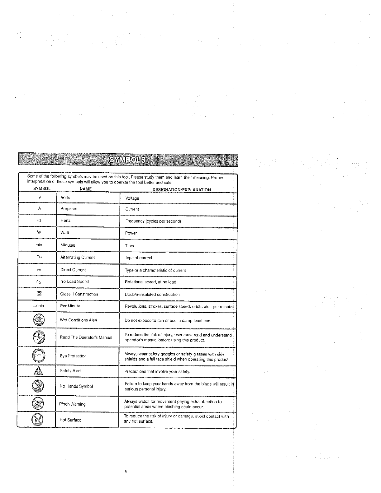
SomeofthefollowingsymbolsmaybeusedonthistoolPleasestudythemandlearntheirmeantng,Proper •
interpretationofthesesymbolswillallowyoutooperatethetoolbetterandsafer,
SYMBOL NAME DESIGNATION/EXPLANATION
V Vogs VoJtage
A
Amperes
Current
Hz
W
rain
no
[]
../rain
@
@
©
A
@
Hertz
Watt
Minules
Alternating Current
Direct Current
No Load Speed
Class II Construction
Per Minute
Wet Conditions Alert
Read The Operator's Manual
Eye Protection
Safety Alert
No Hands Symbol
Frequency (cycles per second)
Power
Time
Type of current
Type or e characteristic of current
Rotational speed, at no load
Doublednsulated construction
Revolutions, strokes, surface speed, orb tse c, per n nute
Do not expose to rain or use in damp locations.
Toreduce the risk of injury, user must read and understand
operator's man_:_albefore using this product.
Always wear safety goggles or safety glasses with side
shields and a full face shield when operating this product,
Precaulions Ihat involve your safety.
Failure to keep your hands away flora Ihe blade wilJ result io
serious personal injury.
@
@
Pinch Warning
Hot Surface
Always watch for movement paying extra attenlion to
potential a_as where pinching could occur.
To"educe the risk of injury or damage, avoid contact with
any hot surface.
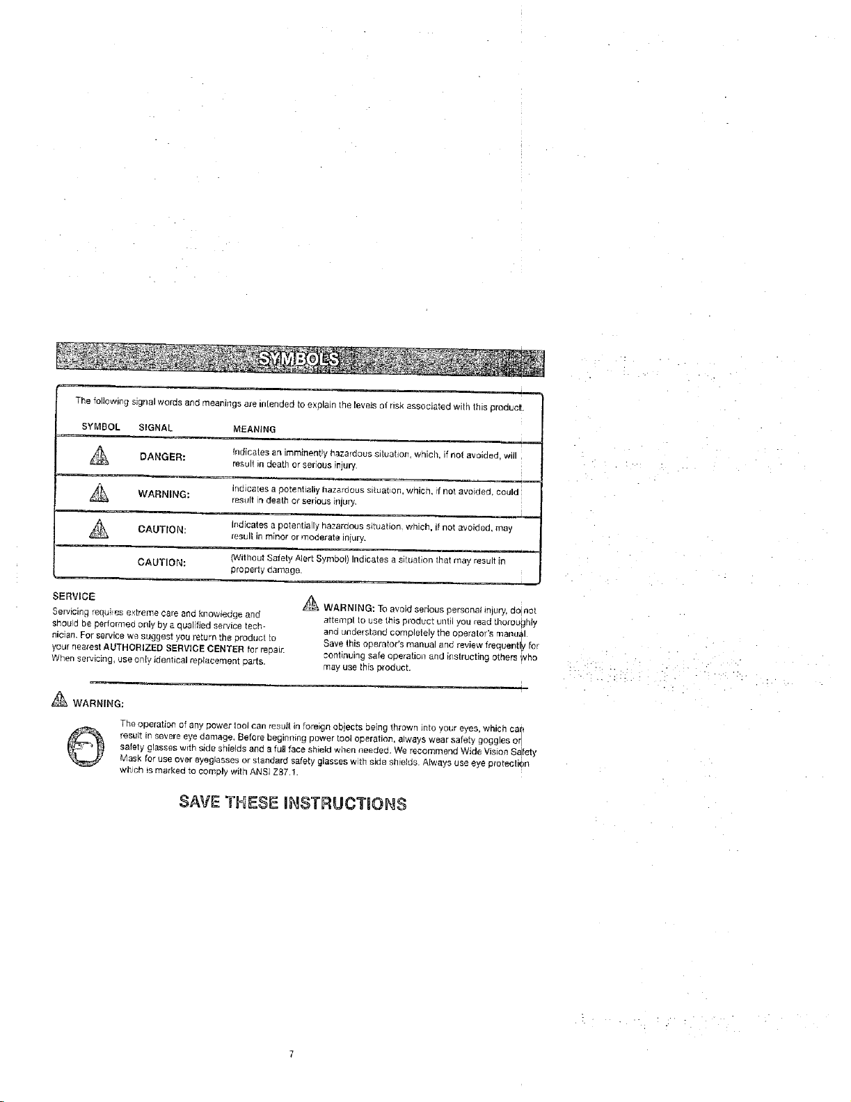
The following signal words and meanings are intended to explain the levels of nsk associated with this eroduct
SYMBOL SIGNAL MEANING
DANGER: result in death or $er cos iiljury,
WARNING:
A result in minor or moderate iniury.
SERVICE
Servicing requites e×trome cote and knowledge and
should be performed only by a qualified service tech
nician, For service we suggest you return the product lo
yournearest AUTHORIZED SERV}CE CENTER for repair.
When servicing, use only identical replacement parts.
_ WARNING:
©
CAUTION:
CAU'[ION: (Without Safely Alert Symbol) Indicates a situation that {"nay result in
The operatia_ of any power tool can result in foreign objects being thrown into your eyes, wmcn car'
result in severe eye damage, Belore beginning power tool operation, always wear satet'y goggles or
safety glasses with side shields and a full face shield when needed• We recommend Wide Vision S_fety
Mask for use over eyeglasses or standard safety glasses w th side shields Always use eye orotectien
whtch is marked to comply with ANSI Z87.1.
Indicates an imrninent!y hazardous siluatlon, which, if not avoided, will
indicates a potenhaliy hazardous situat on, which, f not avoided, could
_esult in death or selbus illjur'j•
Indicates a potentia ly hazardous situation, which, it Rot avoided may
propelly damage.
SAVE THESE INSTRUCTIONS
_-_\ WARNING: To avoid serious personal mlUrY,do not
attempl to use this p_odoct until you read thoroughly
and understand completely the opera[ol s ruanu_l
Save this operator's manual and review frequentl[v for
continuing safe operation and instructing o[ners WhO
may use this product,
EXTENSION CORDS
Use only 3-wire extension cords that have 3-prong
grounding plugs and 3-pole receptacles that accept the
tool's plug. When using a power tooiat aconsiderable
distance from the power source, use an extension cord
heavy enough lo carry the current that the tool will draw.
Art undersized extension cord will cause a drop in line
voltage, resulting in a loss of power and causing the
motor to overheat. Lisa the chart provided below to
determine the minimum wire size required in an extension
cord, Only round jacketed cords listed by Underwdter's
Laboratories (UL) should be used.
"Ampere _atng ton tC_l dale _late t
012,0 2.r-3,4 3.5-5.0 51-70 7,1-12.0 12.1-16.0
Cord Length Wire Size (A.W.G.)
25' !6 16 16 16 14 14
50' 16 16 t5 14 14 12
100' 16 16 14 12 10 -
"*Used on 12 gauge - 20 amp circuit.
NO]E: AWG = Am_ic_r_ Wire G_ge
When working with the tool outdoors, ueean extension
cord that is designed for outside use. This is indicated by
Ihe letters "WA 'ron the cord's jacket.
Before using an extensron cord, inspect it for loose or
exposed wires and cut or worn insulation,
_, WARNING: Keep the extension cord clear of the
working area. Position the cord so that itwill not get
caught on lumber, tools or other obstructions while
you are working with a power tool. Failure le do so
can result in serious personal injury.
[1,
[JL_ WARNING: Check extension cords before each
use. g damaged replace immediately, Never use tool
with a dereaged cord since touching the damaged
area could cause electrical shock resulting in serious
injury,
ELECTRICAL CONNECTION
This tool is powered by a precision buitl electric motor.
It should be connected to a power supply that Is 120
volts, 60 Hz, AC only [normal household current}. Do I
not operate this tool on direct current (DC). A substantial
voltage drop will cause a loss of power and the motor w!ll
overheat. ]f the saw does not operate when plugged intq
an outlet, double check the power supply.
SPEED AND WIRING
The no-load speed of this tool is approy,imateltt _,,800 rp_n.
This speed isnot constant and decreases under s load (_r
with lower voltage. For voltage, the wiring in a shop is a_
important as the motor's horsepower rating A line intend-
ed on_yfor lights cannot properly cart,/a power tool motor.
Wire that is heavy enough for a short distance will be toq
light for a greater distance. A line that can support one |
power tool may not be able to supped two or three tool.
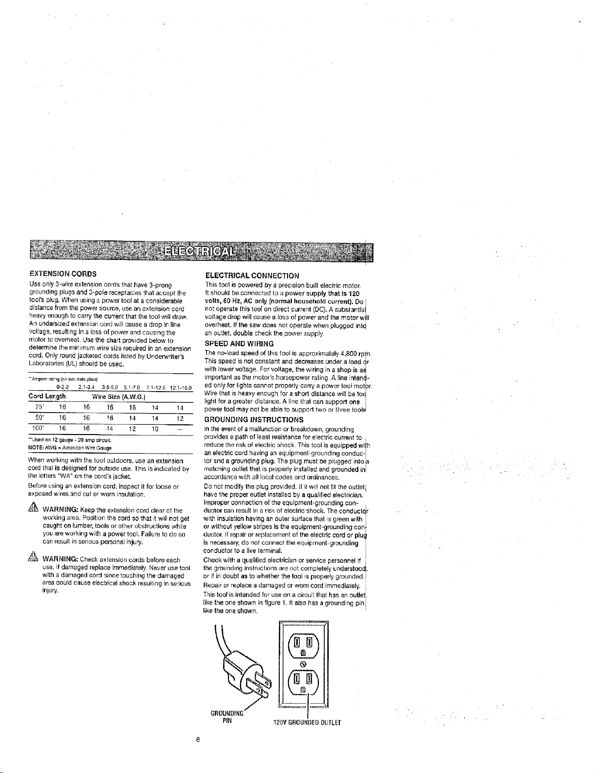
GROUNDING INSTRUCTIONS
Inthe event of a malfunction or breakdown, grounding
provldes a path of leasl resistance for electric current to
reduce the risk of electric shock. This tool isequipped Wilh
an electdc cord having an equipment-grounding conduc- I
tcr and a grounding plug. The plug must be plugged into _a
matching outlet that is properly instarled and grounded in/
accordance with all local codes and ordinances.
Do net modify the plug provided. {fit will not fit the outlet I
have the proper outlet installed by a qualified electrician.
Improper connection of the equipment-grounding con-
duotor can result in a risk of electric shock. The ¢onduclctr
with insulation having an outer surface that is green wil,h
or without yellow stripes is the equipment-grounding con_
ducton If repair or replacement of the etecfric cord or plu_
is necessary, do not connect the equipment grounding "
conductor to a live terminal. I
Check with a qualilied electrician or service personnel if i
the grounding instructions are not completely understood,
or it in doubt a_ to whether the tool is plo[_edy grounded.[
Repairorreplaoeadamagedorworncordimmediately. i
This tool is intended for use on a circuit that has an outlet i
like the one shown in figure 1. It also has a grounding pin i
like the one shown,
®
(gg
120V GR(]g_BEBOUTLEI
• 'i ...... i _ :. :: L ..
Anti-Kickback Pawls (radial arm and table saws)
A device which, when properly installed and maintained
is designed to stop the workplace from being kicked back
toward the front of the saw during a ripping operation.
Arbor
The shaft on which a blade or cutting tool is mounted.
Bevel Gut
A cLltting operation re,ado with the blade at any angle
ether than 90_ to the tab{e sudace.
Chamfer
A cut removing a wedge from a block so the end (or part
of the end) is angled rather than at 90".
Compound Cut
A cross cut made with both a miter and a bevel angb.
Cross Cut
A cutting or shaping operalio=_made across the grain or
the width of the workpiece.
Cutter Heed Iplaners and jointers}
A rotating piece of adjustable btades. The cutter head
removes material from the wod{piece.
Dado Cut
A non-through cut which produces a squa_e-sided notch
or trough in the workpiece (requires a special blade}
Featherboard
A device tJsed to help control the workpiece by guiding it
securely against the table or fence during any ripping
operation.
FPM or SPM
Feet per minute (or strokes per minute}, used inreference
to blade movement.
Freehand
Performing a cat without the workplace being guided by a
fence, miter gauge, or other aids.
Gum
A sticky, sap-based residue from wood products.
Heal
Alignment of the blade lo the fence.
Kerr
]'he matedal removed by the blade in a through cut or the
slot produced by the blade in a non-through or partial cut.
Kickback
A hazard that can occur when the blade binds or stalls,
throwingthe workpiece back toward operator.
Leading End
the end ol the wod_piece pushed into the tool first.
Miter Cut
A curling operation made with the workpiece at any angle
to the blade other lhan 90°.
Non-Through Cuts
Any cutting operalien where the blade does not extol d
completely through the thickness of the workpiece.
Pilot Role (drill presses)
A smatl hole drilled ina workpiece that serves as a gt {de
for dfilhng large holes accurately.
Push 8locks and Push Slicks
Devices used to feed the workpiece through the saw
blade during cutting operations. A push stick (not ap xsh
block} should be used for narrow ripping operations. _/rom
These aids help keep the operator's hands well away
the blade.
Resaw
A cutting operat_n to [educe the thickness of the wor
piece to make thinner p_eces.
Resin
A sticky, sap-based substance that has hardened.
Revelations Per Minute (RPM)
The number of turns completed by a spinning object i
one Minute.
Ripping or Rip Cut
A cutting operation along the length of the workplace.
Riving Knife/SpreaderlSpl_tter (table saws)
A metal piece, sJightlv thinner than the blade, _.¢hiohh,
keep the kerr open and also helps to prevent kickbacl
Sew Blade Path
The area over, under, behind, or }nfront ot the blade. ,_
it applies to the workplace, that area which will be or h
been cut by the blade.
Set
The distance that the tip ef the saw blade tooth is ben1
set) outward from the face of the blade.
Snipe (planers) [
Depression made at either end of a workpiece by cutter
blades when the workpieee is not properly supportedq
Through Sawing |
Any cutting operation where the blade extends completely
through the thickness of the wo[kpiece.
Throw-Back
The throwing back of a workpiece usually caused by tl
workpiece being dropped into the blade or being plact
inadvertently in contact with the blade.
t,Vorl{plece or Material
The item on which the operation is being done
Worktable
Surface where the workpiece rests while performing a
curling, drilling, pianing, or sanding operation.
,?..

PRODUCT SPECIFICATIONS
Blade Arbor .............................................................. 5/8 in. Rating .............................................. 120 V, 50 Hz, AC
Blade Diameter .......................................................... 10 in. Input ................................................................ 15 Amper_
Blade Tilt ................................................................. O° * 45° No Load Speed ................................................. 5,000imi
Net Weight without Leg Stand ............................. 61,5 Ibs. Cutting Depth at 0°: .................................... 3 1/'2 i
Net Weight with Leg Stand ................................... 82.5 Ibs. Cutting Depth at 45": ............................................ 2-1/2 i
OUTFEED
SUPPORT
BRACKET(S}
STORAGE
MITER
FENCE
SPREADER
SLIDING
MITERTABLE
FRONT
RAIL
ANTI-KICKBACK GUARD
PAWLS
BLAOE
RIP FENCE EXTENSION
BEVEL
SCALE
TABLE
LOCKINGLEVEF
TABLETILT
HANDLE
_BEVEL
LOCKING
LEVER
HEIGHT]BEVEL
ADJUSTINGHANDWHEEI
FOOT
F_g
IO
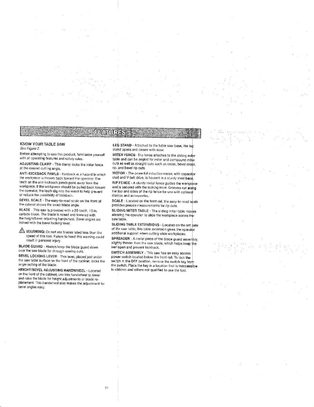
KNOW YOUR TABLE SAW
See Figure 2.
Before attemptin G to use fins aroduct, faml iarize yourself
with at operating features ana safety rules.
ADJUSTING CLAMP - This cramp locks the miter fence
at tne aes_rsd curt ng angle.
ANTI-I(IGKBAOI( PAWLS - Kickback _s a heza,d in wttich
the workplace _sthrown back toward the opera;or: The,
teeth on the eng-k_ckb_c_, paw_s po_r_t away f[om the
workpiece. If the workplace should be Ouilec Back towage
the operator, the teeth dig rote the wood to held arl_vent
or reduce the uo£s_Olll|y of kickback.
BEVEL SCALE - The easy4o-read scale on the froPt Ol
the cabinet shows the exact blade angle
BLADE This saw is providsc with a 36-1ooB" I 0 In.
carbrde blade. The b_aoe Jsrased end lowered with
the heighVbeve adlusting hardwheel. _evel ang'es ale
locked with the be_,el _ock_ng _evsr
_,-_ WARNING: Do not use bla0es rated less rna_ the
speed of this too}. Failure to heed this warning COUId
result i# personal injury.
BLADE GUARD - Always keep the blade guard daws
over the saw blade for through-sawing curs.
BEVEL LOCKING LEVER This ever, sicced just unaer
the saw table surface on the front of the cabinet oaks the
angle setting of the blade
HEIGHT/BEVEL ADJUSTING HANBWN_:EL - Locates
on the front of the cabinet, use this handwheel to lower
and raise the blade for height adjustments or blade re-
placement This t_a_dwhee! a_ao makes the ad,Jstmeet far
bevel angles easy.
LEG STAND * Attached to the table saw base, the le
stand ooens ano ClOSeS WIUq ease.
MITER FENCE- The fence attaches to the sliding rrli
table and can be angled for miter and comsound mg
cut_. as w_II as s_fa_gnt cuts such as cross bevel ere
rip. and bevel ric cuts.
MOTOR - The oeweriul _neuc_on meter, with capaci
starl and V-belt drive Is hodsed _na sturdy steel bas
RiP FENCE - A _turdy metal lence guides the wdrkp
and is secured with the locking lever• Grooves rull ale
the to_ and sides of the - 3 fence for use with optiona
clar_Ds and accessories.
SCALE - Losaled on lhe frort rail. the easy-lo-read s_
provides Dreclse measurements tar rio cute.
SLIDING MtlTER TABLE - The siding miter table mo_
allowing rne coclater to s}ide the worhBlece across lh
sew table.
SLIDING TASLE EXTENSIONS - Located on the left
of the saw table this table extension gwes the costal
additional support when cutting wide workpieoes.
SPREA[}ER - A metal piece of the blade guara assen
slightly '_" nner than the saw blade, which heIps }<eeD
kerr open and prevent kickback.
SWlTC_ ASSEMBLY - This saw has an easy access
cower switch located below the bent rail. To ock the
switch _n the OFF aositior remove the switch key fi'o
the switch. Place the key in a location that is inaeees_
to children and others not 3ualifiec to use the tool.
}r
or
ce
_g
ale
,de
)r
bly.
he
n
ibis
11
i -•- • •
i •
OPERATING COMPONENTS
The upper podioo of the blade pro}ects up through the
tabie and is staTounded by an insert called the throat
plate. The height of the blade is set with a handwheel on
the front of the cabinet. To accommodate wide panels,
the saw table has rails on each aide, Detailed instructions
are provided in the Operation section of this manual for
the basis cuts: cross cuts, miter cuts, bevel cuts, and
compound cuts.
The sliding miter table assembly is used for sloes cutting
operations. The miter fence is easily adjusted to cut wood
at an angle by loosening the adiustJn§ clamp, setting the
fence to the miter scale, and retightening the clamp. The
sliding miter table, which rests on a base mounted on the
rails, can be repositioned along the rails for wide work. it
can be reversed so the projecting base is in the back and
can be moved from the left side to the right side as need-
ed, With the miter fence removed, the miter table offers
additional support for other operations such as ripping.
The rip fence is used to position work for lengthwise cuts.
A scale on the front rail shows the distance between the
rip fence and the blade.
It is very important to use the blade guard assembly for all
Ihrough-sawi#g operations. The blade guard assembly
includes: riving kniteispreader/splitter, anti-kickback
pawls, and plastic blade guard.
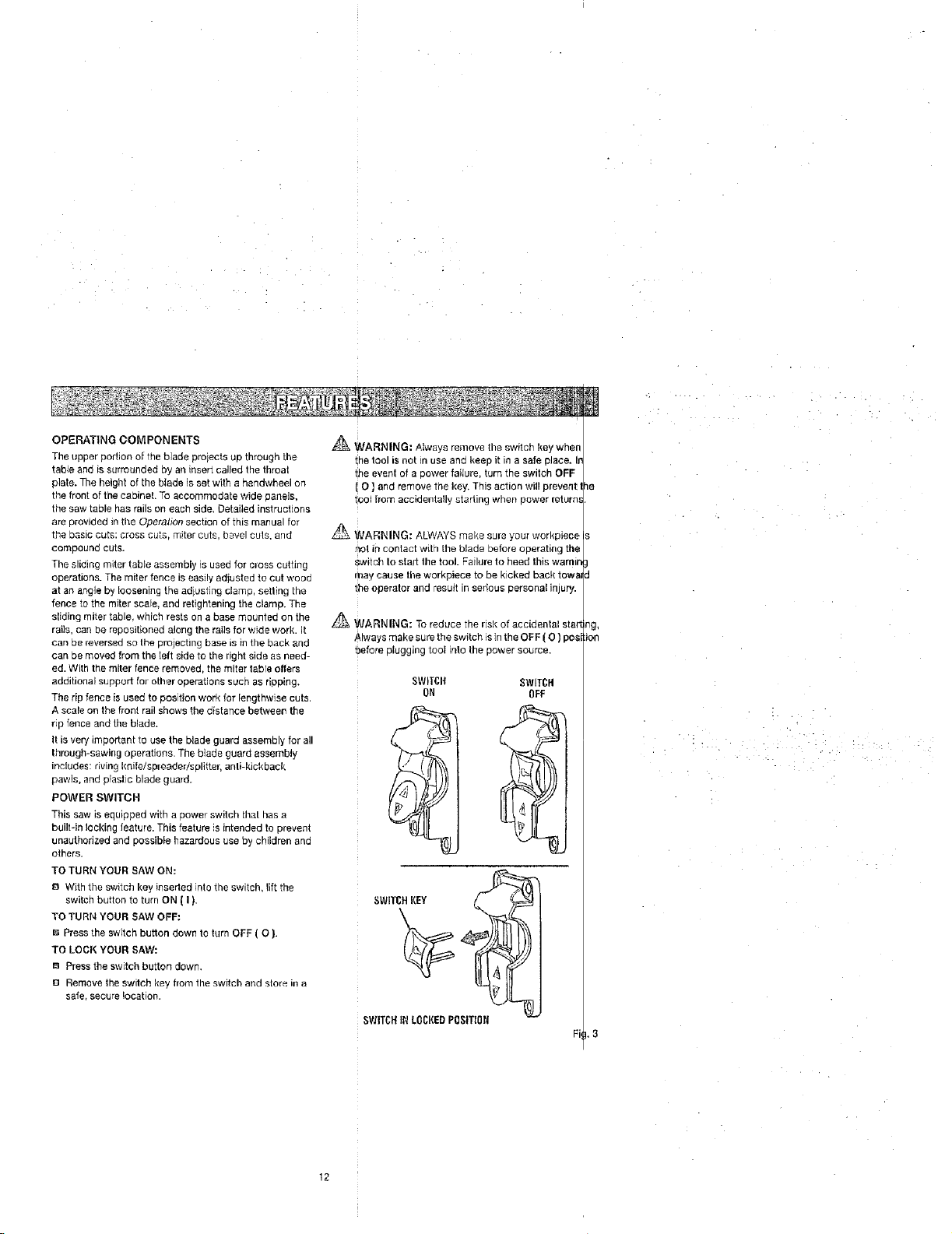
POWER SWITCH
This saw is equipped with a power switch thai has a
built-in locking feature. This feature is intended to prevent
unauthorized and possible hazardous use by children and
others.
TO TURN YOUR SAW ON:
8 With the switch key inserted into the switch, lift the
switch button to turn ON [ I ).
TO TURN YOUR SAW OFF:
I_ Press the switch button down to turn OFF ( O ).
TO LOOK YOUR SAW:
m Press the switch button down.
I_1Remove the switch key from the switch and store in a
safe, secure location.
_ WARNING: Atways remove the switch key when
_hetool is not in use and keep it in a safe place. Ir
the event of a power faiture, turn the switch OFF
O ] and remove the key. This action will prevent I
tool from accidentally starling when power return_
WARNING: ALWAYS make sure your workpiece
not in contact with the blade before operating the
switch to stad the tool. Failure to heed this warnin
may cause tile workpiece to be kicked back towa_
the operator and result in serious personal injury.
WARNING: To reduce the risk of accidental star1
Always make sure the switch is in the OFF (O) pest
before plugging tool into the power source.
SWITCI'I SWITCH
ON OFF
BLADES
For maximum performance, it is recommended that you
use the Craftsman 36-tooth, 10 in. carbide combination
blade provided with your saw, Additiona_ blade styles of
the same high quality are available for specific operat one
such as ripping, Your local dealer can provide you with
complete information,
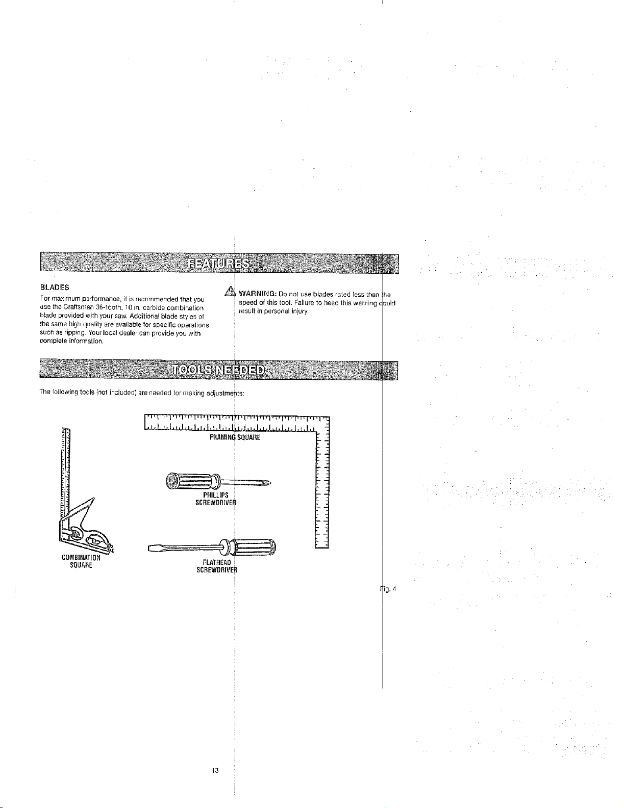
The following tools {not included) are needed for making adjustmenta:
_ WARNING: Do no_ use blades raled less than
speed of this tool. Failure to heed this warning (
result in personal injury.
ould
COMBINATION
SQLIARE
,L_L,J._.#._,, I,,, I, _,!, q,I, bJ.LI, !, _
FRAMINGSQUARE "_
PHILLIPS T "1
SCREWDRNEH : :
FLATHEAD
SCREWDRIVER
;i
ig.4
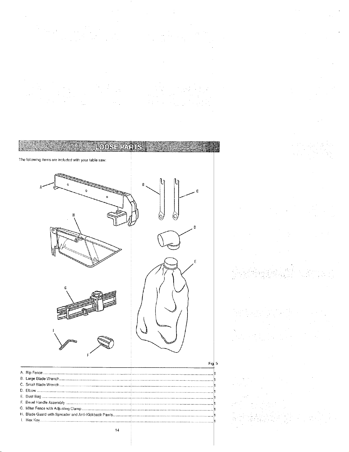
The following items are included wilh your table saw:
6
A. Rip Fence ...................................................................................................................................................................
B. Large Blade Wrench ...................................................................................................................................................
C. Smalt Blade Wrench ................................................................................................................................................
D, Elbow ......................................................................................... _............................................................................
E. Dust Bag ................................................................................................................................................................
E Bevel HandleAssembly ..........................................................................................................................................
G. Miter Fence wi[h Adjusting Clamp ........................................................................................................................... i
H. Blade Guard with Spreader and Anti-Kickback Pawls ...............................................................................................
I Hex Key .............................................................................................................................................................
14
UNPACKING
This product requires assembly.
IJ Carefully lift saw from the carton and place it on a level
work sudace.
NOTE: This too! is heavy. To avoid back injury, keep
your knees bent and lift with your legs, nat your back,
and get help when reeded.
19 Inspect the took carefully to make sure no breakage or
damage occurred during shipping.
E1 Do not discard the pacldng material until you have
carefully iospected and satbfaetobty operated the tool.
The saw is factory set for accurate cutting. After
assembling it, check for accuracy. If shipping has
influenced the settings, refer' to specific procedures
explained in this manual
El if any parts are damaged or missing, please can
1-800-932-3188 for assistance.
_ WARNING: If any parts are missing, do not operate
this tool until the missing parts are replaced. Failure
to do so could result in possible seric)us personal
injury.
_ WARNING: Do not attempt to modify this tool
or create accessories not recommended for use
with this tool Any such alteration or modification is
misuse and could resull in a hazardous condition
leading to possible serious personal injury.
_ WARNING: Do not connect to power supply until
assembly is complete. Failure to comply could result
in accidental starting and possible serious personal
injury.
,_,_"_ WARNING: Do not lift the saw without help. Hold
it close to your body. Keep your knees bent and
lift with your legs, not your back. Ignoring these
precautions can ,esult in back injury.
_ WARNING: Never stand directly in line with the
blade or allow hands 10 come closer than 3 in. to the
blade. Do not reach over or across the blade Failure
to heed this warning can result in serious personal
illlLiry.
A WARNING: To avoid serious personal injury, always
make sure the table saw is securely mounted to
a workbench or an approved leg stand NEVER
operate the saw on the floor.
MOUNTING HOLES
This toot comes mounled to a leg stand. ]f you chose
remove the leg stand, the table saw must be mounted
firm _upporfing surface such as a worl_bench or leg sin _d,
Four bolt holes have been provided in the saw's basel
this porpose. Each of the four mounting holes should b
boll_ securely using 3/8 in. machine botts, lock wash_
and Nex nuts (not included). Bolls should be of sufficiei t
length to accommodate the saw base, lock washers, I_ _x
nuts, and the thickness of the workbench. Tighten all < ur
bolts securely.
Carefully check the workbench after mounting to make
sure that r_omovement can occur du[ng use. If any tip
ping, sliding, or we kirlg is noted, secure the workberi to
the fleer before operating.
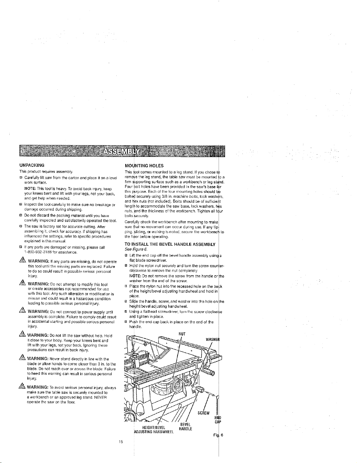
TO INSTALLTHE BEVEL HANDLE ASSEMBL I
See Figure 6. I
r_ Lift the end cap off the bevel handle assembly using Ia
flu i blade screwdriver. /
Ea Hdld [he nylon nut securely and turn the screw couoler-
clockwise to remove the nut completely
NOTE: Do not remove tile screw from the handle o:rlthe
washer from the end of [he screw.
Place the nylon nut into the recessed hole on the ba_,k
of ihe heightibevel adjusting handwheel arid hold in/
pl_ce, l
[] Slide the handle> screw, and washer into the hole on I[he
height/bevel ad _eting handwheeh /
B Using a flatlqead screwdriver, iul n the screw clockwise
and tighten in place. /
[] Push the end cap back in place on the end of the
handle.
NUT
I
i
/
ftEIGItTIBEVEL HANDLE
ADJUSTINGftANBWHEEL
BEVEL
 Loading...