

Craftsman 315212380 Owner’s Manual

PERATOR'S MAN AL
T
10 in. COMPOUND MITER SAW WiTH LASER
DOUBLE iNSULATED
Model No.
315.212380
_ WARNING" To reduce the risk of injury,
the user must read and understand the
operator's manual before using this product.
Customer Help Line: 1-800-932-3188
Sears, Roebuck and Co., 3333 Beverly Rd., Hoffman Estates, IL 60179 USA
Visit the Craftsman web page: www.sears.com/craftsman
987000-21 5
02-08-08 (REV:04)
Save this manual for future reference
• Warranty ............................................................................................................................................................................ 2
• Introduction ....................................................................................................................................................................... 2
• General Safety Rules ..................................................................................................................................................... 3-4
• Specific Safety Rules ..................................................................................................................................................... 4-5
• Symbols ......................................................................................................................................................................... 6-7
• Electrical ............................................................................................................................................................................ 8
• Glossary of Terms .............................................................................................................................................................. 9
• Features ..................................................................................................................................................................... 10-12
• Tools Needed .................................................................................................................................................................. 13
• Loose Parts ..................................................................................................................................................................... 14
• Assembly ................................................................................................................................................................... 15-26
• Operation ................................................................................................................................................................... 26-32
• Adjustments ............................................................................................................................................................... 33-34
• Maintenance .............................................................................................................................................................. 35-36
• Exploded View ........................................................................................................................................................... 37-49
• Parts Ordering/Service ...................................................................................................................................... Back Page
ONE YEAR FULL WARRANTY ON CRAFTSMAN TOOL
If this Craftsman tool fails due to a defect in material or workmanship within one year from the date of purchase,
CONTACT THE NEAREST SEARS PARTS & REPAIR CENTER at 1-800-4-MY-HOME ® and Sears will repair it, free of
charge. This warranty applies only while this product is in the United States.
If this tool is used for commercial or rental purposes, this warranty will apply for only ninety days from the date of
purchase.
This warranty gives you specific legal rights, and you may also have other rights which vary from state to state.
Sears, Roebuck and Co., Dept. 817WA, Hoffman Estates, IL 60179
This product has many features for making its use more pleasant and enjoyable. Safety, performance, and dependability
have been given top priority in the design of this product making it easy to maintain and operate.
_ WARNING:Readandunderstandall instruc-
tions. Failure to follow all instructions listed below,
may result in electric shock, fire and/or serious
personal injury.
READ ALL INSTRUCTIONS
[] KNOW YOUR POWER TOOL. Read the operator's
manual carefully. Learn the saw's applications and
limitations as well as the specific potential hazards
related to this tool.
[] GUARD AGAINST ELECTRICAL SHOCK BY PRE-
VENTING BODY CONTACT WiTH GROUNDED
SURFACES. For example, pipes, radiators, ranges,
refrigerator enclosures.
[] KEEP GUARDS IN PLACE and in good working order.
[] REMOVE ADJUSTING KEYS AND WRENCHES.
Form habit of checking to see that keys and adjusting
wrenches are removed from tool before turning it on.
[] KEEP WORK AREA CLEAN. Cluttered areas and
benches invite accidents. DO NOT leave tools or
pieces of wood on the saw while it is in operation.
[] DO NOT USE IN DANGEROUS ENVIRONMENTS.
Do not use power tools in damp or wet locations or
expose to rain. Keep the work area well lit.
[] KEEP CHILDREN AND VISITORS AWAY. All visitors
should wear safety glasses and be kept a safe
distance from work area. Do not let visitors contact tool
or extension cord while operating.
[] MAKE WORKSHOP CHILDPROOF with padlocks and
master switches, or by removing starter keys.
[] DON'T FORCE TOOL. It will do the job better and
safer at the feed rate for which it was designed.
[] USE RIGHT TOOL. Don't force the tool or attachment
to do a job it was not designed for. Don't use it for a
purpose not intended.
[] USE THE PROPER EXTENSION CORD. Make sure
your extension cord is in good condition. Use only a
cord heavy enough to carry the current your product
will draw. An undersized cord will cause a drop in line
voltage resulting in loss of power and overheating. A
wire gauge size (A.W.G.) of at least 14 is recommended
for an extension cord 25 feet or less in length. If in
doubt, use the next heavier gauge. The smaller the
gauge number, the heavier the cord.
[] DRESS PROPERLY. Do not wear loose clothing,
gloves, neckties, or jewelry. They can get caught
and draw you into moving parts. Rubber gloves and
nonskid footwear are recommended when working
outdoors. Also wear protective hair covering to contain
long hair.
[] ALWAYS WEAR SAFETY GLASSES WITH SIDE
SHIELDS. Everyday eyeglasses have only impact-
resistant lenses, they are NOT safety glasses.
[] SECURE WORK. Use clamps or a vise to hold work
when practical. It's safer than using your hand and
frees both hands to operate tool.
[] DON'T OVERREACH. Keep proper footing and
balance at all times.
[] MAINTAIN TOOLS WITH CARE. Keep tools sharp
and clean for better and safer performance. Follow
instructions for lubricating and changing accessories.
[] DISCONNECT TOOLS. When not in use, before
servicing, or when changing attachments, blades, bits,
cutters, etc., all tools should be disconnected.
[] AVOID ACCIDENTAL STARTING. Be sure switch is off
when plugging in any tool.
[] USE RECOMMENDED ACCESSORIES. The use of
improper accessories may risk injury.
[] NEVER STAND ON TOOL. Serious injury could occur
if the tool is tipped or if the cutting tool is unintention-
ally contacted.
[] CHECK DAMAGED PARTS. Before further use of
the tool, a guard or other part that is damaged should
be carefully checked to determine that it will operate
properly and perform its intended function. Check for
alignment of moving parts, binding of moving parts,
breakage of parts, mounting and any other conditions
that may affect its operation. A guard or other part that
is damaged must be properly repaired or replaced by
an authorized service center to avoid risk of personal
injury.
[] USE THE RIGHT DIRECTION OF FEED. Feed work
into a blade or cutter against the direction of rotation of
blade or cutter only.
[] NEVER LEAVE TOOL RUNNING UNATTENDED.
TURN THE POWER OFF. Don't leave tool until it
comes to a complete stop.
[] PROTECT YOUR LUNGS. Wear a face or dust mask if
the cutting operation is dusty.
[] PROTECT YOUR HEARING. Wear hearing protection
during extended periods of operation.
[] DO NOT ABUSE CORD. Never yank cord to discon-
nect from receptacle. Keep cord from heat, oil, and
sharp edges.
[] USE OUTDOOR EXTENSION CORDS. When tool is
used outdoors, use only extension cords with ap-
proved ground connection that are intended for use
outdoors and so marked.
[] KEEP BLADES CLEAN, SHARP, AND WITH SUF-
FICIENT SET. Sharp blades minimize stalling and
kickback.
[]
BLADE COASTS AFTER BEING TURNED OFF.
[]
NEVER USE IN AN EXPLOSIVE ATMOSPHERE.
Normal sparking of the motor could ignite fumes.
[] iNSPECT TOOL CORDS PERiODiCALLY. If damaged,
have repaired by a qualified service technician at
an authorized service facility. The conductor with
insulation having an outer surface that is green with
or without yellow stripes is the equipment-ground-
ing conductor. If repair or replacement of the electric
cord or plug is necessary, do not connect the equip-
ment-grounding conductor to a live terminal. Repair
or replace a damaged or worn cord immediately. Stay
constantly aware of cord location and keep it well away
from the rotating blade.
[] INSPECT EXTENSION CORDS PERIODICALLY and
replace if damaged.
[] POLARIZED PLUGS. To reduce the risk of electric
shock, this tool has a polarized plug (one blade is
wider than the other). This plug will fit in a polarized
outlet only one way. If the plug does not fit fully in the
outlet, reverse the plug. If it still does not fit, contact a
qualified electrician to install the proper outlet. Do not
change the plug in any way.
[] KEEP TOOL DRY, CLEAN, AND FREE FROM OiL
AND GREASE. Always use a clean cloth when clean-
ing. Never use brake fluids, gasoline, petroleum-based
products, or any solvents to clean tool.
[] STAY ALERT AND EXERCISE CONTROL. Watch
what you are doing and use common sense. Do not
operate tool when you are tired. Do not rush.
[] DO NOT USE TOOL IF SWITCH DOES NOT TURN IT
ON AND OFF. Have defective switches replaced by an
authorized service center.
[] USE ONLY CORRECT BLADES. Do not use blades
with incorrect size holes. Never use blade washers or
blade bolts that are defective or incorrect. The maxi-
mum blade capacity of your saw is 10 in. (254 mm).
[] BEFORE MAKING A CUT, BE SURE ALL ADJUST-
MENTS ARE SECURE.
[] BE SURE BLADE PATH IS FREE OF NAILS. Inspect
for and remove all nails from lumber before cutting.
[] NEVER TOUCH BLADE or other moving parts during
use.
[] NEVER START A TOOL WHEN ANY ROTAT-
ING COMPONENT IS IN CONTACT WITH THE
WORKPIECE.
[] DO NOT OPERATE A TOOL WHILE UNDER THE
INFLUENCE OF DRUGS, ALCOHOL, OR ANY
MEDICATION.
[] WHEN SERVICING use only identical replacement
parts. Use of any other parts may create a hazard or
cause product damage.
[] USE ONLY RECOMMENDED ACCESSORIES listed
in this manual or addendums. Use of accessories
that are not listed may cause the risk of personal
injury. Instructions for safe use of accessories are
included with the accessory.
[] DOUBLE CHECK ALL SETUPS. Make sure blade is
tight and not making contact with saw or workpiece
before connecting to power supply.
[] FIRMLY CLAMP OR BOLT your miter saw to a
workbench or table at approximately hip height.
[] KEEP HANDS AWAY FROM CUTTING AREA. Do not
reach underneath work or in blade cutting path with
your hands and fingers for any reason. Always turn the
power off.
[] ALWAYS SUPPORT LONG WORKPIECES while
cutting to minimize risk of blade pinching and
kickback. Saw may slip, walk or slide while cutting long
or heavy boards.
[] ALWAYS USE A CLAMP to secure the workpiece
when possible.
[] BE SURE THE BLADE CLEARS THE WORKPIECE.
Never start the saw with the blade touching the
workpiece. Allow motor to come up to full speed
before starting cut.
[] MAKE SURE THE MITER TABLE AND SAW ARM
(BEVEL FUNCTION} ARE LOCKED IN POSITION
BEFORE OPERATING YOUR SAW. Lock the miter
table by securely tightening the miter lock levers. Lock
the saw arm (bevel function) by securely tightening the
bevel lock knob.
[] NEVER USE A LENGTH STOP ON THE FREE SCRAP
END OF A CLAMPED WORKPIECE. NEVER hold
onto or bind the free scrap end of the workpiece in any
operation. If a work clamp and length stop are used
together, they must both be installed on the same side
of the saw table to prevent the saw from catching the
loose end and kicking up.
[] NEVER cut more than one piece at a time. DO NOT
STACK more than one workpiece on the saw table at a
time.
[] NEVER PERFORM ANY OPERATION FREEHAND.
Always place the workpiece to be cut on the miter
table and position it firmly against the fence as a
backstop. Always use the fence.
[] NEVERhandholdaworkpiecethatistoosmalltobe
clamped.Keephandsclearofthecuttingarea.
[] NEVERreachbehind,under,orwithinthreeinches
ofthebladeanditscuttingpathwithyourhandsand
fingersforanyreason.
[] NEVERreachto pickupaworkpiece,apieceofscrap,
oranythingelsethatisinornearthecuttingpathofthe
blade.
[] AVOIDAWKWARDOPERATIONS AND HAND
POSITIONS where a sudden sup could cause your
hand to move into the blade. ALWAYS make sure you
have good balance. NEVER operate your miter saw
on the floor or in a crouched position.
[] NEVER stand or have any part of your body in line with
the path of the saw blade.
[] ALWAYS release the power switch and allow the
saw blade to stop rotating before raising it out of the
workpiece.
[] DO NOT TURN THE MOTOR SWITCH ON AND OFF
RAPIDLY. This could cause the saw blade to loosen
and could create a hazard. Should this ever occur,
stand clear and allow the saw blade to come to a
complete stop. Disconnect your saw from the power
supply and securely retighten the blade bolt.
[] IF ANY PART OF THIS MITER SAW IS MISSING or
should break, bend, or fail in any way, or should any
electrical component fail to perform properly, shut off
the power switch, remove the miter saw plug from the
power source and have damaged, missing, or failed
parts replaced before resuming operation.
[] ALWAYS STAY ALERT! Do not allow familiarity (gained
from frequent use of your saw) to cause a careless
mistake. ALWAYS REMEMBER that a careless fraction
of a second is sufficient to inflict severe injury.
[] MAKE SURE THE WORK AREA HAS AMPLE
LIGHTING to see the work and that no obstructions
will interfere with safe operation BEFORE performing
any work using your saw.
[] ALWAYS TURN OFF THE SAW before disconnecting
it to avoid accidental starting when reconnecting to
power supply. NEVER leave the saw unattended while
connected to a power source.
[] THIS TOOL should have the following markings:
a) Wear eye protection.
b) Keep hands out of path of saw blade
c) Do not operate saw without guards in place.
d) Do not perform any operation freehand.
e) Never reach around saw blade.
f) Turn off tool and wait for saw blade to stop before
moving workpiece or changing settings.
g) Disconnect power (or unplug tool as applicable)
before changing blade or servicing.
h) No load speed.
[] ALWAYS carry the tool only by the carrying handle.
[] AVOID direct eye exposure when using the laser guide.
[] IF THE POWER SUPPLY CORD IS DAMAGED, it
must be replaced only by the manufacturer or by an
authorized service center to avoid risk.
[] SAVE THESE INSTRUCTIONS. Refer to them
frequently and use them to instruct others who may
use this power tool. If you loan someone this power
tool, loan them these instructions also.
_IL WARNING: Some dust created by power sanding, sawing, grinding, drilling, and other construction activities
contains chemicals known to cause cancer, birth defects or other reproductive harm. Some examples of these
chemicals are:
• lead from lead-based paints,
crystalline silica from bricks and cement and other masonry products, and
arsenic and chromium from chemically-treated lumber.
Your risk from these exposures varies, depending on how often you do this type of work. To reduce your exposure
to these chemicals: work in a well ventilated area, and work with approved safety equipment, such as those dust
masks that are specially designed to filter out microscopic particles.

Someofthefollowingsymbolsmaybeusedonthisproduct.Pleasestudythemandlearntheirmeaning.Properin-
terpretationofthesesymbolswillallowyoutooperatetheproductbetterandsafer.
SYMBOL NAME DESIGNATION/EXPLANATION
V
A
mz
W
min
=.--=.#_
no
[]
.../min
Volts
Amperes
Hertz
Watt
Minutes
Alternating Current
Direct Current
No Load Speed
Class II Construction
Per Minute
Voltage
Current
Frequency (cycles per second)
Power
Time
Type of current
Type or a characteristic of current
Rotational speed, at no load
Double-insulated construction
Revolutions, strokes, surface speed, orbits etc., per minute
@
@
O
,&
@
@
@
Wet Conditions Alert
Read The Operator's Manual
Eye Protection
Safety Alert
No Hands Symbol
No Hands Symbol
No Hands Symbol
No Hands Symbol
Do not expose to rain or use in damp locations.
To reduce the risk of injury, user must read and understand
operator's manual before using this product.
Always wear safety goggles or safety glasses with side shields and,
as necessary, a full face shield when operating this product.
Precautions that involve your safety.
Failure to keep your hands away from the blade will result in
serious personal injury.
Failure to keep your hands away from the blade will result in
serious personal injury.
Failure to keep your hands away from the blade will result in
serious personal injury.
Failure to keep your hands away from the blade will result in
serious personal injury.
®
Hot Surface
To reduce the risk of injury or damage, avoid contact with any
hot surface.
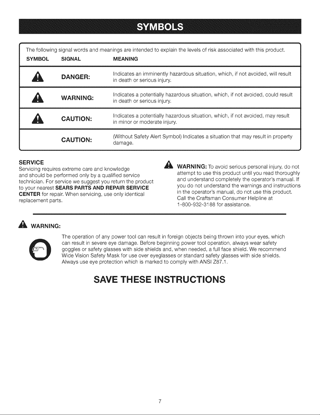
Thefollowingsignalwordsandmeaningsareintendedtoexplainthelevelsofriskassociatedwiththisproduct.
SYMBOL SIGNAL MEANING
DANGER:
_, Indicates a potentially hazardous situation, which, if not avoided, could result
WARNING: in death or serious injury.
CAUTION:
CAUTION:
SERVICE
Servicing requires extreme care and knowledge
and should be performed only by a qualified service
technician. For service we suggest you return the product
to your nearest SEARS PARTS AND REPAIR SERVICE
CENTER for repair. When servicing, use only identical
replacement parts.
,_ WARNING:
Indicates an imminently hazardous situation, which, if not avoided, will result
in death or serious injury.
Indicates a potentially hazardous situation, which, if not avoided, may result
in minor or moderate injury.
(Without Safety Alert Symbol) Indicates a situation that may result in property
damage.
A
WARNING: To avoid serious personal injury,do not
attempt to use this product until you read thoroughly
and understand completely the operator's manual. If
you do not understand the warnings and instructions
in the operator's manual, do not use this product.
Call the Craftsman Consumer Helpline at
1-800-932-3188 for assistance.
The operation of any power tool can result in foreign objects being thrown into your eyes, which
can result in severe eye damage. Before beginning power tool operation, always wear safety
goggles or safety glasses with side shields and, when needed, a full face shield. We recommend
Wide Vision Safety Mask for use over eyeglasses or standard safety glasses with side shields.
Always use eye protection which is marked to comply with ANSI Z87.1.
SAVE THESE INSTRUCTIONS
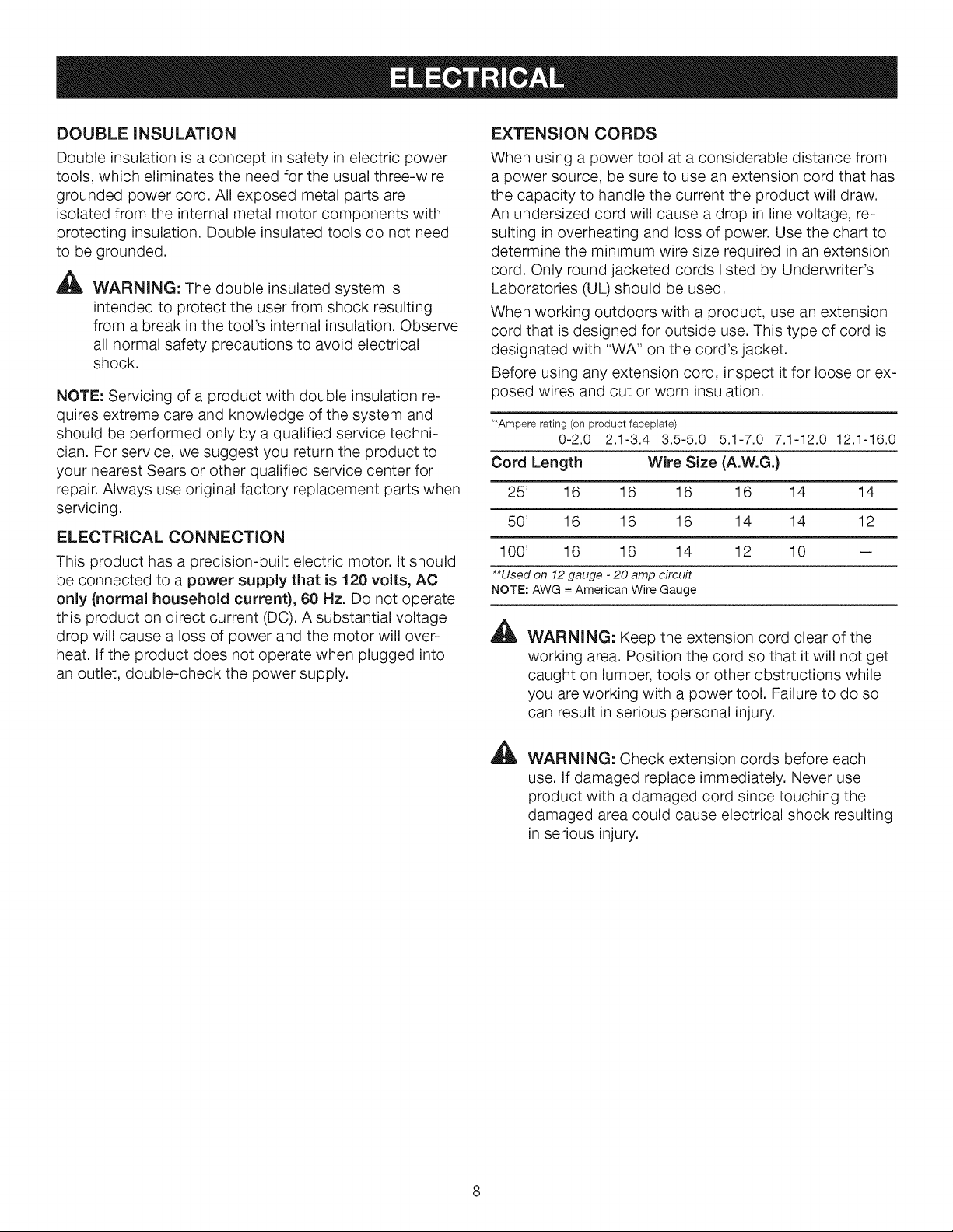
DOUBLE INSULATION
Double insulation is a concept in safety in electric power
tools, which eliminates the need for the usual three-wire
grounded power cord. All exposed metal parts are
isolated from the internal metal motor components with
protecting insulation. Double insulated tools do not need
to be grounded.
_IIL WARNING: The double insulated system is
intended to protect the user from shock resulting
from a break in the tool's internal insulation. Observe
all normal safety precautions to avoid electrical
shock.
NOTE: Servicing of a product with double insulation re-
quires extreme care and knowledge of the system and
should be performed only by a qualified service techni-
cian. For service, we suggest you return the product to
your nearest Sears or other qualified service center for
repair. Always use original factory replacement parts when
servicing.
ELECTRICAL CONNECTION
This product has a precision-built electric motor. It should
be connected to a power supply that is 120 volts, AC
only (normal household current), 60 Hz. Do not operate
this product on direct current (DC). A substantial voltage
drop will cause a loss of power and the motor will over-
heat. If the product does not operate when plugged into
an outlet, double-check the power supply.
EXTENSION CORDS
When using a power tool at a considerable distance from
a power source, be sure to use an extension cord that has
the capacity to handle the current the product will draw.
An undersized cord will cause a drop in line voltage, re-
suiting in overheating and loss of power. Use the chart to
determine the minimum wire size required in an extension
cord. Only round jacketed cords listed by Underwriter's
Laboratories (UL) should be used.
When working outdoors with a product, use an extension
cord that is designed for outside use. This type of cord is
designated with "WA" on the cord's jacket.
Before using any extension cord, inspect it for loose or ex-
posed wires and cut or worn insulation.
**Ampere rating (on product faceplate)
Cord Length Wire Size (A.W.G.)
25' 16 16 16 16 14 14
50' 16 16 16 14 14 12
100' 16 16 14 12 10 --
**Used on 12 gauge - 20 amp circuit
NOTE: AWG = American Wire Gauge
A
0-2.0 2.1-3.4 3.5-5.0 5.1-7.0 7.1-12.0 12.1-16.0
WARNING: Keep the extension cord clear of the
working area. Position the cord so that it will not get
caught on lumber, tools or other obstructions while
you are working with a power tool. Failure to do so
can result in serious personal injury.
A
WARNING: Check extension cords before each
use. If damaged replace immediately. Never use
product with a damaged cord since touching the
damaged area could cause electrical shock resulting
in serious injury.
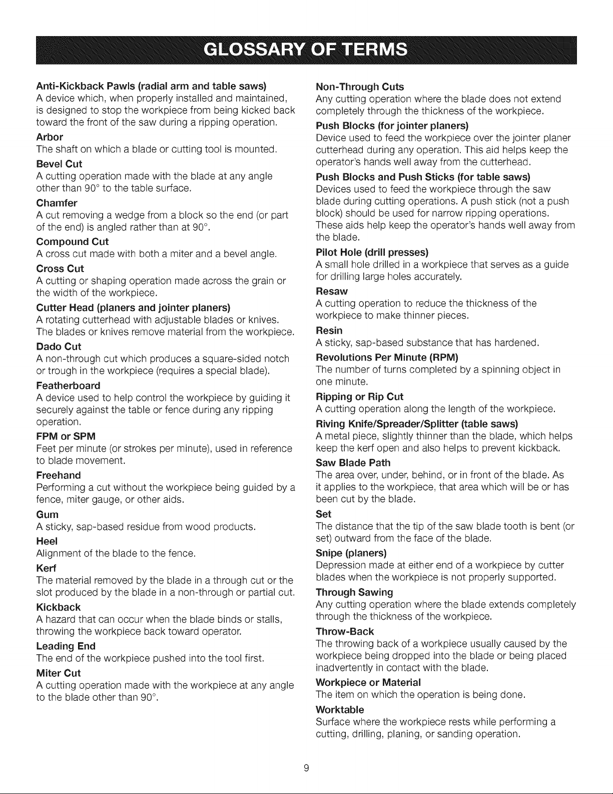
Anti-KickbackPawls (radial arm and table saws)
A device which, when properly installed and maintained,
is designed to stop the workpiece from being kicked back
toward the front of the saw during a ripping operation.
Arbor
The shaft on which a blade or cutting tool is mounted.
Bevel Cut
A cutting operation made with the blade at any angle
other than 90 ° to the table surface.
Chamfer
A cut removing a wedge from a block so the end (or part
of the end) is angled rather than at 90°.
Compound Cut
A cross cut made with both a miter and a bevel angle.
Cross Cut
A cutting or shaping operation made across the grain or
the width of the workpiece.
Cutter Head (planers and jointer planers)
A rotating cutterhead with adjustable blades or knives.
The blades or knives remove material from the workpiece.
Dado Cut
A non-through cut which produces a square-sided notch
or trough in the workpiece (requires a special blade).
Featherboard
A device used to help control the workpiece by guiding it
securely against the table or fence during any ripping
operation.
FPM or SPM
Feet per minute (or strokes per minute), used in reference
to blade movement.
Freehand
Performing a cut without the workpiece being guided by a
fence, miter gauge, or other aids.
Gum
A sticky, sap-based residue from wood products.
Heel
Alignment of the blade to the fence.
Kerr
The material removed by the blade in a through cut or the
slot produced by the blade in a non-through or partial cut.
Kickback
A hazard that can occur when the blade binds or stalls,
throwing the workpiece back toward operator.
Leading End
The end of the workpiece pushed into the tool first.
Miter Cut
A cutting operation made with the workpiece at any angle
to the blade other than 90°.
Non-Through Cuts
Any cutting operation where the blade does not extend
completely through the thickness of the workpiece.
Push Blocks (for jointer planers)
Device used to feed the workpiece over the jointer planer
cutterhead during any operation. This aid helps keep the
operator's hands well away from the cutterhead.
Push Blocks and Push Sticks (for table saws)
Devices used to feed the workpiece through the saw
blade during cutting operations. A push stick (not a push
block) should be used for narrow ripping operations.
These aids help keep the operator's hands well away from
the blade.
Pilot Hole (drill presses)
A small hole drilled in a workpiece that serves as a guide
for drilling large holes accurately.
Resaw
A cutting operation to reduce the thickness of the
workpiece to make thinner pieces.
Resin
A sticky, sap-based substance that has hardened.
Revolutions Per Minute (RPM)
The number of turns completed by a spinning object in
one minute.
Ripping or Rip Cut
A cutting operation along the length of the workpiece.
Riving Knife/Spreader/Splitter (table saws)
A metal piece, slightly thinner than the blade, which helps
keep the kerf open and also helps to prevent kickback.
Saw Blade Path
The area over, under, behind, or in front of the blade. As
it applies to the workpiece, that area which will be or has
been cut by the blade.
Set
The distance that the tip of the saw blade tooth is bent (or
set) outward from the face of the blade.
Snipe (planers)
Depression made at either end of a workpiece by cutter
blades when the workpiece is not properly supported.
Through Sawing
Any cutting operation where the blade extends completely
through the thickness of the workpiece.
Throw-Back
The throwing back of a workpiece usually caused by the
workpiece being dropped into the blade or being placed
inadvertently in contact with the blade.
Workpiece or Material
The item on which the operation is being done.
Worktable
Surface where the workpiece rests while performing a
cutting, drilling, planing, or sanding operation.
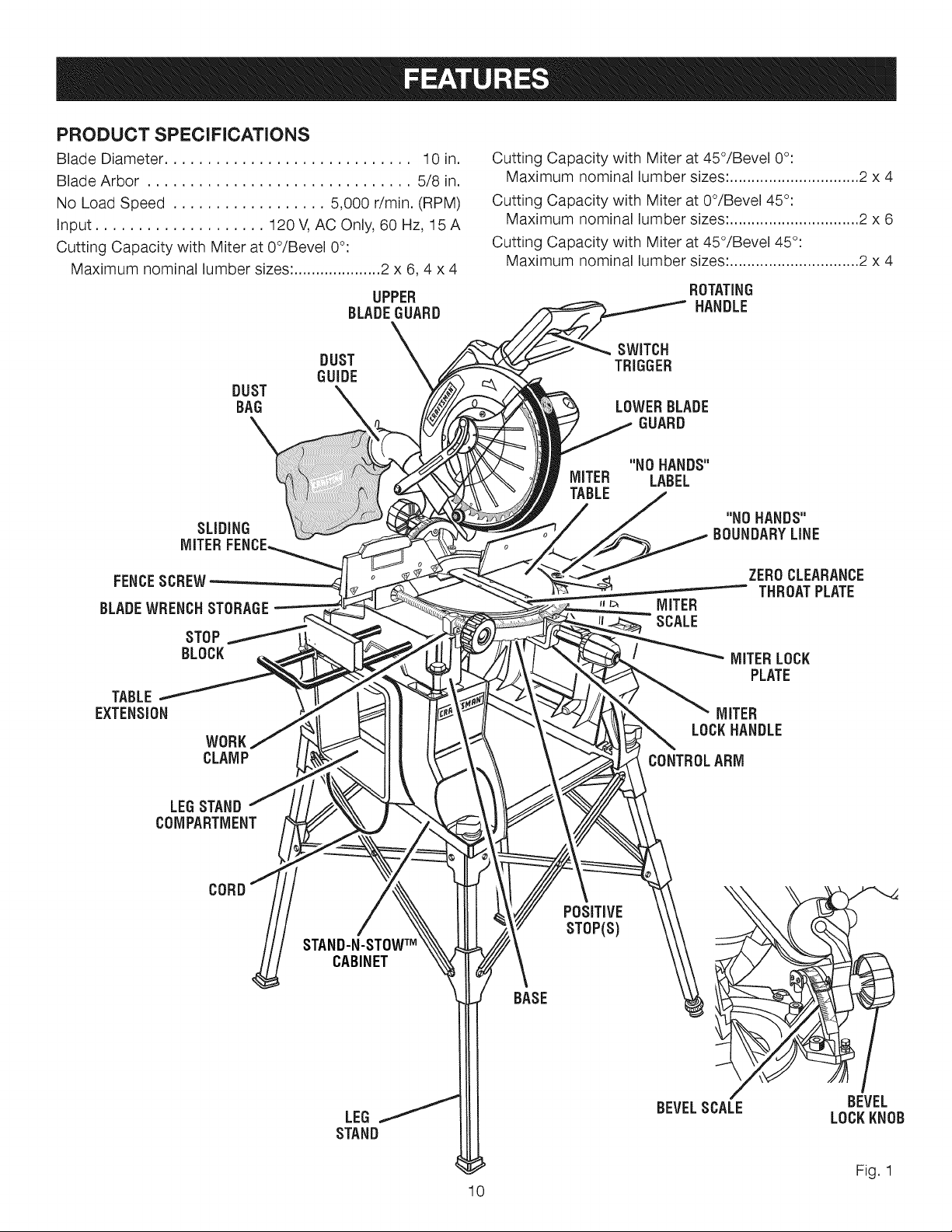
PRODUCT SPECIFICATIONS
Blade Diameter ............................. 30 in.
Blade Arbor ............................... 5/8 in.
No Load Speed .................. 5,000 r/min. (RPM)
Input .................... 120V, AC Only, 60 Hz, 15A
Cutting Capacity with Miter at 0°/Bevel 0°:
Maximum nominal lumber sizes: .................... 2 x 6, 4 x 4
UPPER
BLADEGUARD
Cutting Capacity with Miter at 45°/Bevel 0°:
Maximum nominal lumber sizes: .............................. 2 x 4
Cutting Capacity with Miter at 0°/Bevel 45°:
Maximum nominal lumber sizes: .............................. 2 x 6
Cutting Capacity with Miter at 45°/Bevel 45°:
Maximum nominal lumber sizes: .............................. 2 x 4
ROTATING
HANDLE
DUST
BAG
SLiDiNG
MITER
FENCESCREW
BLADEWRENCHSTORAGE
STOP
BLOCK
TABLE
EXTENSION
WORK
CLAMP
DUST
GUIDE
MITER
TABLE
SWITCH
TRIGGER
LOWER BLADE
GUARD
"NO HANDS"
LABEL
"NO HANDS"
BOUNDARYLINE
ZEROCLEARANCE
THROATPLATE
MITER
SCALE
MITER LOCK
PLATE
MITER
LOCKHANDLE
CONTROL ARM
LEGSTAND
COMPARTMENT
CORD
STAND-N-STOWTM
CABINET
LEG
STAND
POSiTiVE
STOP(S)
BASE
/
BEVELSCALE BEVEL
LOCKKNOB
Fig. 1
10
KNOW YOUR COMPOUND MITER SAW
See Figure 1.
The safe use of this product requires an understanding
of the information on the product and in this operator's
manual as well as a knowledge of the project you are
attempting. Before use of this product, familiarize yourself
with all operating features and safety rules.
10 in. BLADE
A 10 in. carbide-tipped saw blade is included with your
compound miter saw. It will cut materials up to 4 in. thick
or 6 in. wide, depending upon the angle at which the cut
is being made.
15 AMP MOTOR
Your saw has a powerful 15 amp motor with sufficient
power to handle tough cutting jobs. It is made with all ball
bearings, and has externally accessible brushes for ease
of servicing.
BEVEL LOCK KNOB
The bevel lock knob securely locks your compound
miter saw at desired bevel angles. A positive stop
adjustment screw has been provided on each side of the
saw arm. These adjustment screws are for making fine
adjustments at 0° and 45°.
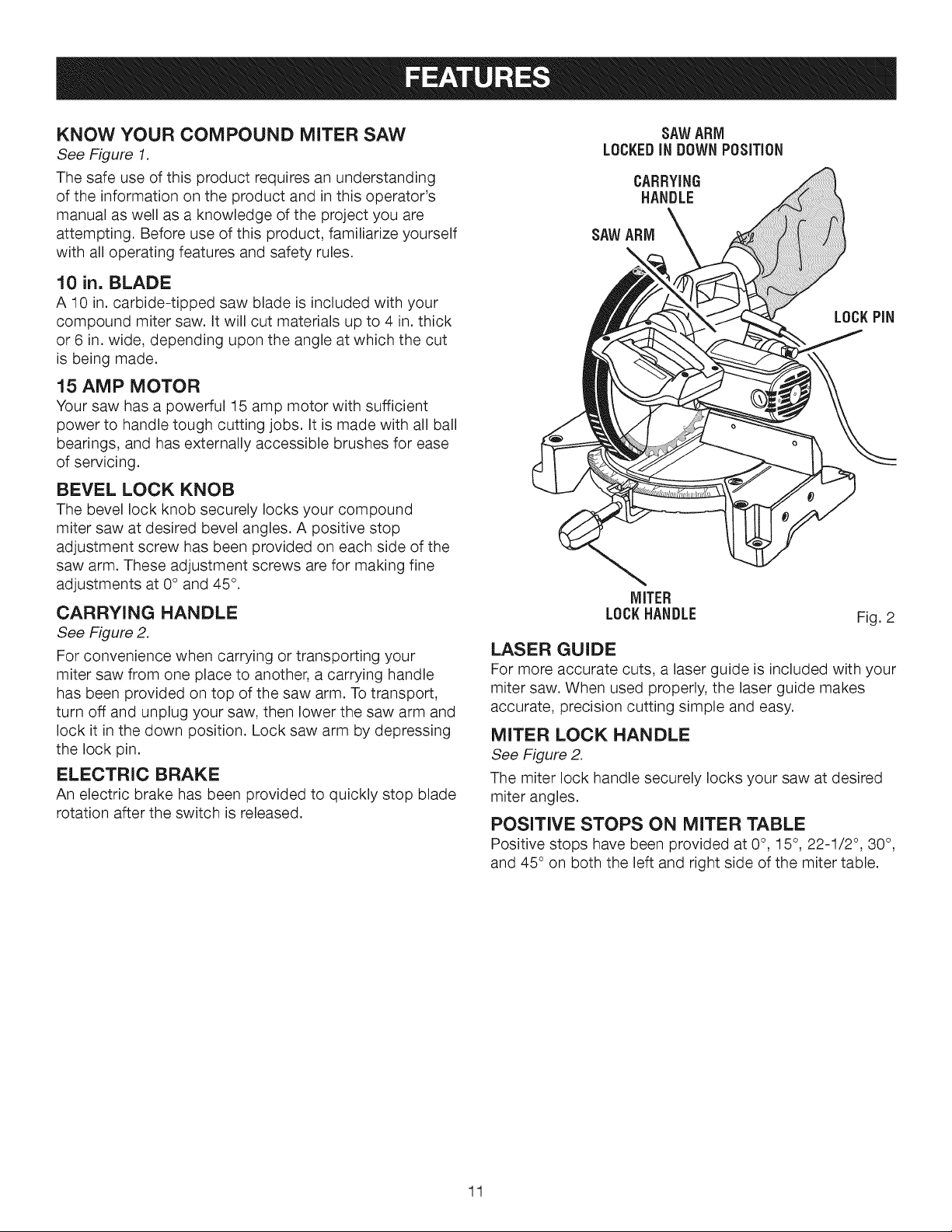
CARRYING HANDLE
See Figure 2.
For convenience when carrying or transporting your
miter saw from one place to another, a carrying handle
has been provided on top of the saw arm. To transport,
turn off and unplug your saw, then lower the saw arm and
lock it in the down position. Lock saw arm by depressing
the lock pin.
ELECTRIC BRAKE
An electric brake has been provided to quickly stop blade
rotation after the switch is released.
SAWARM
LOCKEDIN DOWNPOSITION
CARRYING
HANDLE
SAWARM
LOCKPiN
MITER
LOCKHANDLE
Fig. 2
LASER GUIDE
For more accurate cuts, a laser guide is included with your
miter saw. When used properly, the laser guide makes
accurate, precision cutting simple and easy.
MITER LOCK HANDLE
See Figure 2.
The miter lock handle securely locks your saw at desired
miter angles.
POSITIVE STOPS ON MITER TABLE
Positive stops have been provided at 0°, 15°, 22-1/2 °, 30°,
and 45 ° on both the left and right side of the miter table.
11
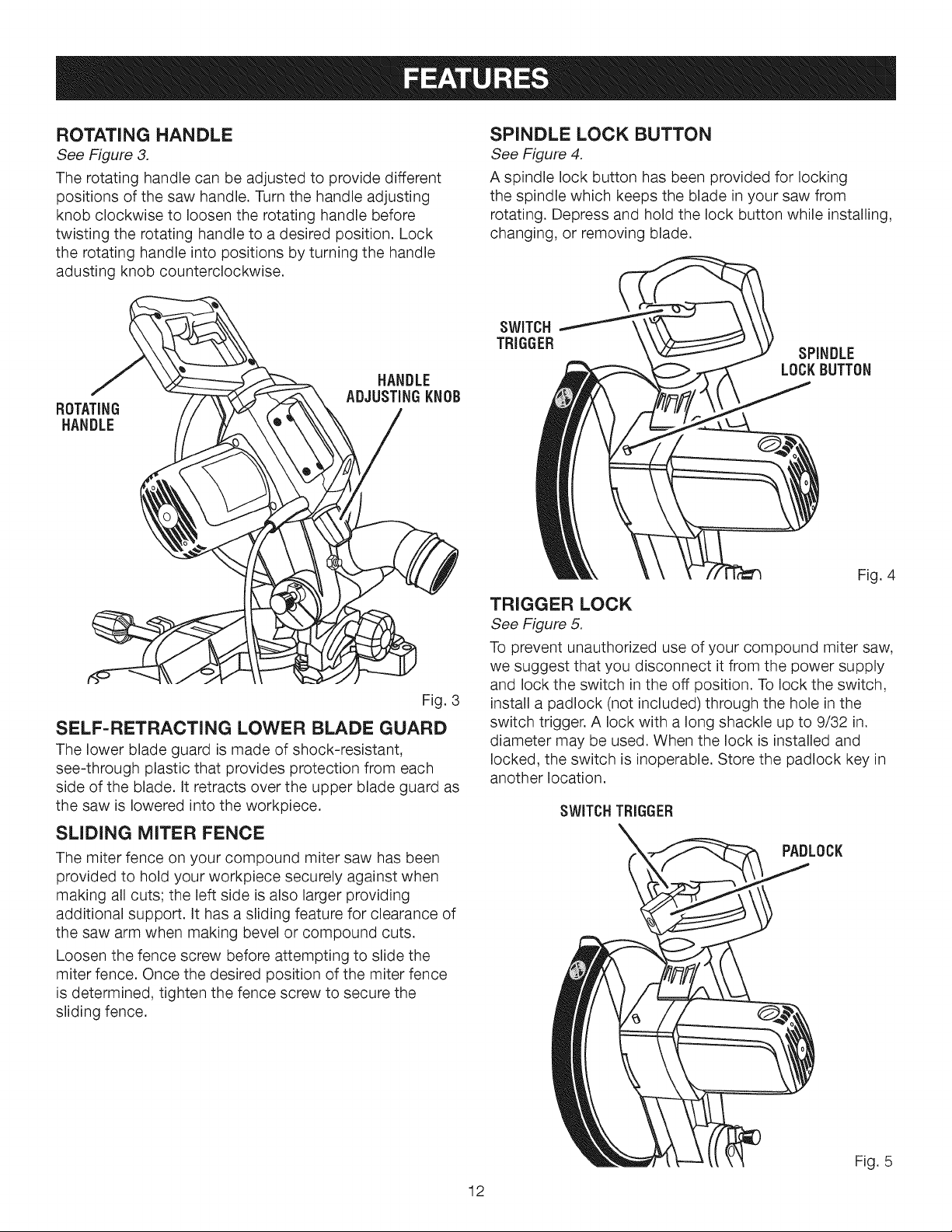
ROTATING HANDLE
See Figure 3.
The rotating handle can be adjusted to provide different
positions of the saw handle. Turn the handle adjusting
knob clockwise to loosen the rotating handle before
twisting the rotating handle to a desired position. Lock
the rotating handle into positions by turning the handle
adusting knob counterclockwise.
HANDLE
ADJUSTING KNOB
ROTATING
HANDLE
SPINDLE LOCK BUTTON
See Figure 4.
A spindle lock button has been provided for locking
the spindle which keeps the blade in your saw from
rotating. Depress and hold the lock button while installing,
changing, or removing blade.
SPINDLE
LOCK BUTTON
Fig. 4
Fig. 3
SELF=RETRACTING LOWER BLADE GUARD
The lower blade guard is made of shock-resistant,
see-through plastic that provides protection from each
side of the blade. It retracts over the upper blade guard as
the saw is lowered into the workpiece.
SLIDING MITER FENCE
The miter fence on your compound miter saw has been
provided to hold your workpiece securely against when
making all cuts; the left side is also larger providing
additional support. It has a sliding feature for clearance of
the saw arm when making bevel or compound cuts.
Loosen the fence screw before attempting to slide the
miter fence. Once the desired position of the miter fence
is determined, tighten the fence screw to secure the
sliding fence.
TRIGGER LOCK
See Figure 5.
To prevent unauthorized use of your compound miter saw,
we suggest that you disconnect it from the power supply
and lock the switch in the off position. To lock the switch,
install a padlock (not included) through the hole in the
switch trigger. A lock with a long shackle up to 9/32 in.
diameter may be used. When the lock is installed and
locked, the switch is inoperable. Store the padlock key in
another location.
SWITCHTRIGGER
PADLOCK
12
Fig. 5
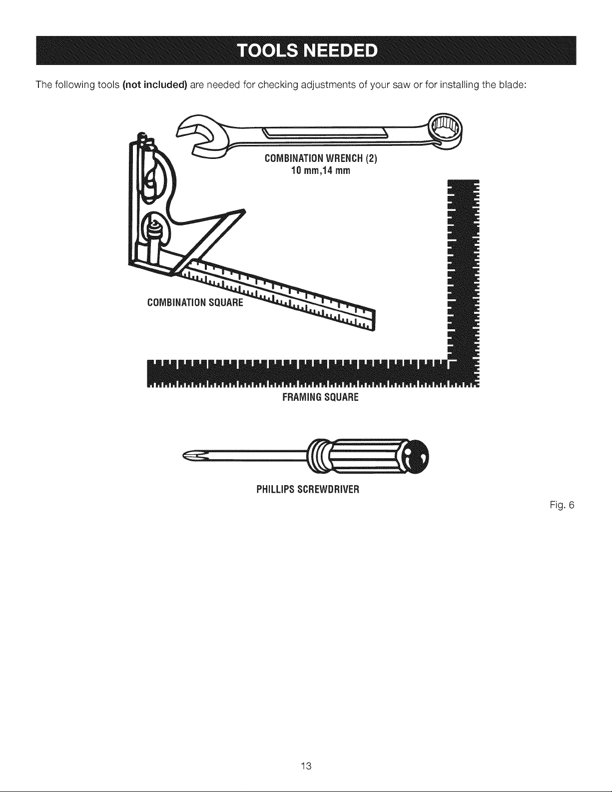
Thefollowingtools(notincluded) are needed for checking adjustments of your saw or for installing the blade:
FRAMINGSQUARE
PHiLLiPSSCREWDRIVER
Fig. 6
13
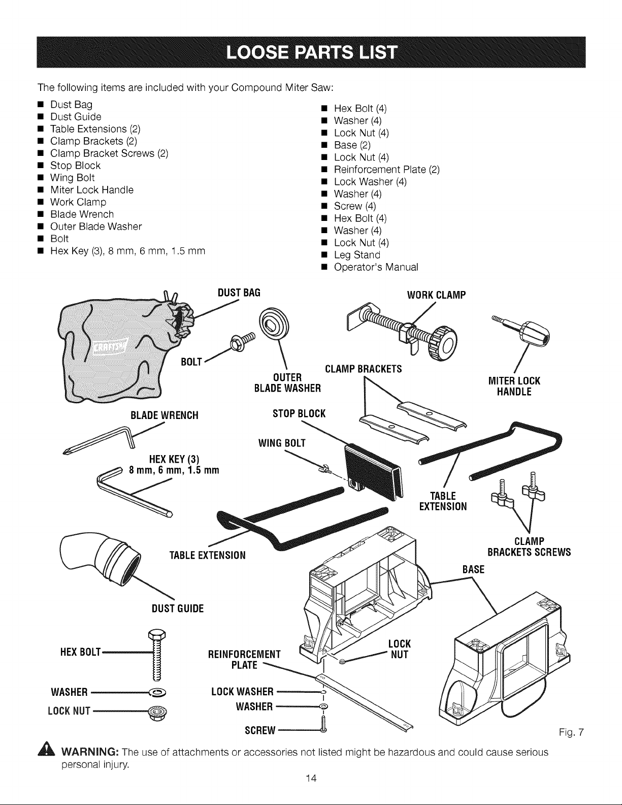
ThefollowingitemsareincludedwithyourCompoundMiterSaw:
• DustBag
• DustGuide
• TableExtensions(2)
• ClampBrackets(2)
• ClampBracketScrews(2)
• StopBlock
• WingBolt
• MiterLockHandle
• WorkClamp
• BladeWrench
• OuterBladeWasher
• Bolt
• HexKey(3),8 mm,6 mm,1.5mm
• HexBolt(4)
• Washer(4)
• LockNut(4)
• Base(2)
• LockNut(4)
• ReinforcementPlate(2)
• LockWasher(4)
• Washer(4)
• Screw(4)
• HexBolt(4)
• Washer(4)
• LockNut(4)
• LegStand
• Operator'sManual
BOLTf
BLADEWRENCH
HEXKEY(3)
8 mm, 6 mm, 1,5 mm
_ _IABLE EX
DUSTBAG
BLADEWASHER
OUTER
STOPBLOCK
WINGBOLT
WORKCLAMP
CLAMPBRACKETS
MITER LOCK
HANDLE
BRACKETSSCREWS
BASE
CLAMP
DUSTGUIDE
LOCK
HEXBOLT---_
WASHER
LOCKNUT
_lL WARNING: The use of attachments or accessories not listed might be hazardous and could cause serious
personal injury.
REINFORCEMENT _ NUT
PLATE_
LOCKWASHER
WASHER_ __
14
Fig. 7
UNPACKING
This product requires assembly.
• Carefully lift saw from the carton by the carrying handle
and the saw base, and place it on a level work surface.
NOTE: This saw is heavy. To avoid back injury, lift with
your legs, not your back, and get help when needed.
• This saw has been shipped with the saw arm secured
in the down position. To release the saw arm, push
down on the top of the saw arm, cut the tie-wrap, and
pull out on the lock pin.
• Lift the saw arm by the handle. Hand pressure should
remain on the saw arm to prevent sudden rise upon
release of the tie wrap.
• Inspect the tool carefully to make sure no breakage or
damage occurred during shipping.
• Do not discard the packing material until you have
carefully inspected and satisfactorily operated the tool.
• The saw is factory set for accurate cutting. After
assembling it, check for accuracy. If shipping has
influenced the settings, refer to specific procedures
explained in this manual.
If any parts are damaged or missing, please call
1-800-932-3188 for assistance.
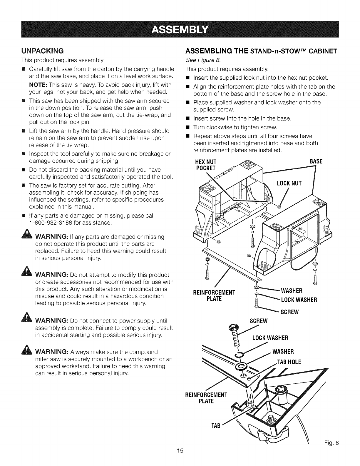
ASSEMBLING THE STAND-n-STOW TM CABINET
See Figure 8.
This product requires assembly.
• Insert the supplied lock nut into the hex nut pocket.
• Align the reinforcement plate holes with the tab on the
bottom of the base and the screw hole in the base.
• Place supplied washer and lock washer onto the
supplied screw.
• Insert screw into the hole in the base.
• Turn clockwise to tighten screw.
• Repeat above steps until all four screws have
been inserted and tightened into base and both
reinforcement plates are installed.
HEXNUT BASE
POCKET
WARNING: If any parts are damaged or missing
do not operate this product until the parts are
replaced. Failure to heed this warning could result
in serious personal injury.
A
WARNING: Do not attempt to modify this product
or create accessories not recommended for use with
this product. Any such alteration or modification is
misuse and could result in a hazardous condition
leading to possible serious personal injury.
A
WARNING: Do not connect to power supply until
assembly is complete. Failure to comply could result
in accidental starting and possible serious injury.
A
WARNING: Always make sure the compound
miter saw is securely mounted to a workbench or an
approved workstand. Failure to heed this warning
can result in serious personal injury.
REINFORCEMENT _o_ WASHER
PLATE ' _ LOCKWASHER
oSCREW
SCREW
'_CK WASHER
WASHER
TABHOLE
REINFORCEMENT
PLATE
15
TAB
Fig. 8
 Loading...